EP1555492A2 - Verfahren zur Steuerung einer multifunktionnellen Klimaanlage - Google Patents
Verfahren zur Steuerung einer multifunktionnellen Klimaanlage Download PDFInfo
- Publication number
- EP1555492A2 EP1555492A2 EP04014490A EP04014490A EP1555492A2 EP 1555492 A2 EP1555492 A2 EP 1555492A2 EP 04014490 A EP04014490 A EP 04014490A EP 04014490 A EP04014490 A EP 04014490A EP 1555492 A2 EP1555492 A2 EP 1555492A2
- Authority
- EP
- European Patent Office
- Prior art keywords
- temperature
- refrigerant
- turned
- opening
- indoor
- Prior art date
- Legal status (The legal status is an assumption and is not a legal conclusion. Google has not performed a legal analysis and makes no representation as to the accuracy of the status listed.)
- Withdrawn
Links
Images




Classifications
-
- F—MECHANICAL ENGINEERING; LIGHTING; HEATING; WEAPONS; BLASTING
- F25—REFRIGERATION OR COOLING; COMBINED HEATING AND REFRIGERATION SYSTEMS; HEAT PUMP SYSTEMS; MANUFACTURE OR STORAGE OF ICE; LIQUEFACTION SOLIDIFICATION OF GASES
- F25B—REFRIGERATION MACHINES, PLANTS OR SYSTEMS; COMBINED HEATING AND REFRIGERATION SYSTEMS; HEAT PUMP SYSTEMS
- F25B5/00—Compression machines, plants or systems, with several evaporator circuits, e.g. for varying refrigerating capacity
- F25B5/02—Compression machines, plants or systems, with several evaporator circuits, e.g. for varying refrigerating capacity arranged in parallel
-
- F—MECHANICAL ENGINEERING; LIGHTING; HEATING; WEAPONS; BLASTING
- F25—REFRIGERATION OR COOLING; COMBINED HEATING AND REFRIGERATION SYSTEMS; HEAT PUMP SYSTEMS; MANUFACTURE OR STORAGE OF ICE; LIQUEFACTION SOLIDIFICATION OF GASES
- F25B—REFRIGERATION MACHINES, PLANTS OR SYSTEMS; COMBINED HEATING AND REFRIGERATION SYSTEMS; HEAT PUMP SYSTEMS
- F25B13/00—Compression machines, plants or systems, with reversible cycle
-
- F—MECHANICAL ENGINEERING; LIGHTING; HEATING; WEAPONS; BLASTING
- F25—REFRIGERATION OR COOLING; COMBINED HEATING AND REFRIGERATION SYSTEMS; HEAT PUMP SYSTEMS; MANUFACTURE OR STORAGE OF ICE; LIQUEFACTION SOLIDIFICATION OF GASES
- F25B—REFRIGERATION MACHINES, PLANTS OR SYSTEMS; COMBINED HEATING AND REFRIGERATION SYSTEMS; HEAT PUMP SYSTEMS
- F25B2313/00—Compression machines, plants or systems with reversible cycle not otherwise provided for
- F25B2313/006—Compression machines, plants or systems with reversible cycle not otherwise provided for two pipes connecting the outdoor side to the indoor side with multiple indoor units
-
- F—MECHANICAL ENGINEERING; LIGHTING; HEATING; WEAPONS; BLASTING
- F25—REFRIGERATION OR COOLING; COMBINED HEATING AND REFRIGERATION SYSTEMS; HEAT PUMP SYSTEMS; MANUFACTURE OR STORAGE OF ICE; LIQUEFACTION SOLIDIFICATION OF GASES
- F25B—REFRIGERATION MACHINES, PLANTS OR SYSTEMS; COMBINED HEATING AND REFRIGERATION SYSTEMS; HEAT PUMP SYSTEMS
- F25B2313/00—Compression machines, plants or systems with reversible cycle not otherwise provided for
- F25B2313/023—Compression machines, plants or systems with reversible cycle not otherwise provided for using multiple indoor units
- F25B2313/0232—Compression machines, plants or systems with reversible cycle not otherwise provided for using multiple indoor units with bypasses
- F25B2313/02323—Compression machines, plants or systems with reversible cycle not otherwise provided for using multiple indoor units with bypasses during heating
-
- F—MECHANICAL ENGINEERING; LIGHTING; HEATING; WEAPONS; BLASTING
- F25—REFRIGERATION OR COOLING; COMBINED HEATING AND REFRIGERATION SYSTEMS; HEAT PUMP SYSTEMS; MANUFACTURE OR STORAGE OF ICE; LIQUEFACTION SOLIDIFICATION OF GASES
- F25B—REFRIGERATION MACHINES, PLANTS OR SYSTEMS; COMBINED HEATING AND REFRIGERATION SYSTEMS; HEAT PUMP SYSTEMS
- F25B2313/00—Compression machines, plants or systems with reversible cycle not otherwise provided for
- F25B2313/023—Compression machines, plants or systems with reversible cycle not otherwise provided for using multiple indoor units
- F25B2313/0233—Compression machines, plants or systems with reversible cycle not otherwise provided for using multiple indoor units in parallel arrangements
- F25B2313/02331—Compression machines, plants or systems with reversible cycle not otherwise provided for using multiple indoor units in parallel arrangements during cooling
-
- F—MECHANICAL ENGINEERING; LIGHTING; HEATING; WEAPONS; BLASTING
- F25—REFRIGERATION OR COOLING; COMBINED HEATING AND REFRIGERATION SYSTEMS; HEAT PUMP SYSTEMS; MANUFACTURE OR STORAGE OF ICE; LIQUEFACTION SOLIDIFICATION OF GASES
- F25B—REFRIGERATION MACHINES, PLANTS OR SYSTEMS; COMBINED HEATING AND REFRIGERATION SYSTEMS; HEAT PUMP SYSTEMS
- F25B2313/00—Compression machines, plants or systems with reversible cycle not otherwise provided for
- F25B2313/023—Compression machines, plants or systems with reversible cycle not otherwise provided for using multiple indoor units
- F25B2313/0233—Compression machines, plants or systems with reversible cycle not otherwise provided for using multiple indoor units in parallel arrangements
- F25B2313/02334—Compression machines, plants or systems with reversible cycle not otherwise provided for using multiple indoor units in parallel arrangements during heating
-
- F—MECHANICAL ENGINEERING; LIGHTING; HEATING; WEAPONS; BLASTING
- F25—REFRIGERATION OR COOLING; COMBINED HEATING AND REFRIGERATION SYSTEMS; HEAT PUMP SYSTEMS; MANUFACTURE OR STORAGE OF ICE; LIQUEFACTION SOLIDIFICATION OF GASES
- F25B—REFRIGERATION MACHINES, PLANTS OR SYSTEMS; COMBINED HEATING AND REFRIGERATION SYSTEMS; HEAT PUMP SYSTEMS
- F25B2500/00—Problems to be solved
- F25B2500/12—Sound
-
- F—MECHANICAL ENGINEERING; LIGHTING; HEATING; WEAPONS; BLASTING
- F25—REFRIGERATION OR COOLING; COMBINED HEATING AND REFRIGERATION SYSTEMS; HEAT PUMP SYSTEMS; MANUFACTURE OR STORAGE OF ICE; LIQUEFACTION SOLIDIFICATION OF GASES
- F25B—REFRIGERATION MACHINES, PLANTS OR SYSTEMS; COMBINED HEATING AND REFRIGERATION SYSTEMS; HEAT PUMP SYSTEMS
- F25B2500/00—Problems to be solved
- F25B2500/19—Calculation of parameters
-
- F—MECHANICAL ENGINEERING; LIGHTING; HEATING; WEAPONS; BLASTING
- F25—REFRIGERATION OR COOLING; COMBINED HEATING AND REFRIGERATION SYSTEMS; HEAT PUMP SYSTEMS; MANUFACTURE OR STORAGE OF ICE; LIQUEFACTION SOLIDIFICATION OF GASES
- F25B—REFRIGERATION MACHINES, PLANTS OR SYSTEMS; COMBINED HEATING AND REFRIGERATION SYSTEMS; HEAT PUMP SYSTEMS
- F25B2500/00—Problems to be solved
- F25B2500/24—Low amount of refrigerant in the system
-
- F—MECHANICAL ENGINEERING; LIGHTING; HEATING; WEAPONS; BLASTING
- F25—REFRIGERATION OR COOLING; COMBINED HEATING AND REFRIGERATION SYSTEMS; HEAT PUMP SYSTEMS; MANUFACTURE OR STORAGE OF ICE; LIQUEFACTION SOLIDIFICATION OF GASES
- F25B—REFRIGERATION MACHINES, PLANTS OR SYSTEMS; COMBINED HEATING AND REFRIGERATION SYSTEMS; HEAT PUMP SYSTEMS
- F25B2600/00—Control issues
- F25B2600/25—Control of valves
- F25B2600/2513—Expansion valves
-
- F—MECHANICAL ENGINEERING; LIGHTING; HEATING; WEAPONS; BLASTING
- F25—REFRIGERATION OR COOLING; COMBINED HEATING AND REFRIGERATION SYSTEMS; HEAT PUMP SYSTEMS; MANUFACTURE OR STORAGE OF ICE; LIQUEFACTION SOLIDIFICATION OF GASES
- F25B—REFRIGERATION MACHINES, PLANTS OR SYSTEMS; COMBINED HEATING AND REFRIGERATION SYSTEMS; HEAT PUMP SYSTEMS
- F25B2700/00—Sensing or detecting of parameters; Sensors therefor
- F25B2700/21—Temperatures
- F25B2700/2104—Temperatures of an indoor room or compartment
-
- F—MECHANICAL ENGINEERING; LIGHTING; HEATING; WEAPONS; BLASTING
- F25—REFRIGERATION OR COOLING; COMBINED HEATING AND REFRIGERATION SYSTEMS; HEAT PUMP SYSTEMS; MANUFACTURE OR STORAGE OF ICE; LIQUEFACTION SOLIDIFICATION OF GASES
- F25B—REFRIGERATION MACHINES, PLANTS OR SYSTEMS; COMBINED HEATING AND REFRIGERATION SYSTEMS; HEAT PUMP SYSTEMS
- F25B2700/00—Sensing or detecting of parameters; Sensors therefor
- F25B2700/21—Temperatures
- F25B2700/2106—Temperatures of fresh outdoor air
-
- F—MECHANICAL ENGINEERING; LIGHTING; HEATING; WEAPONS; BLASTING
- F25—REFRIGERATION OR COOLING; COMBINED HEATING AND REFRIGERATION SYSTEMS; HEAT PUMP SYSTEMS; MANUFACTURE OR STORAGE OF ICE; LIQUEFACTION SOLIDIFICATION OF GASES
- F25B—REFRIGERATION MACHINES, PLANTS OR SYSTEMS; COMBINED HEATING AND REFRIGERATION SYSTEMS; HEAT PUMP SYSTEMS
- F25B2700/00—Sensing or detecting of parameters; Sensors therefor
- F25B2700/21—Temperatures
- F25B2700/2117—Temperatures of an evaporator
- F25B2700/21174—Temperatures of an evaporator of the refrigerant at the inlet of the evaporator
-
- F—MECHANICAL ENGINEERING; LIGHTING; HEATING; WEAPONS; BLASTING
- F25—REFRIGERATION OR COOLING; COMBINED HEATING AND REFRIGERATION SYSTEMS; HEAT PUMP SYSTEMS; MANUFACTURE OR STORAGE OF ICE; LIQUEFACTION SOLIDIFICATION OF GASES
- F25B—REFRIGERATION MACHINES, PLANTS OR SYSTEMS; COMBINED HEATING AND REFRIGERATION SYSTEMS; HEAT PUMP SYSTEMS
- F25B2700/00—Sensing or detecting of parameters; Sensors therefor
- F25B2700/21—Temperatures
- F25B2700/2117—Temperatures of an evaporator
- F25B2700/21175—Temperatures of an evaporator of the refrigerant at the outlet of the evaporator
Definitions
- the present invention relates to multi-type air conditioner, and more particularly, to a method for controlling a multi-type air conditioner which enables to minimize stagnation of refrigerant at turned off indoor units during some of the indoor units are in operation for heating rooms, and reduce noise occurred when the stagnant refrigerant is removed.
- the air conditioner is an apparatus for cooling or heating rooms, such as residential space, restaurant, office, and the like.
- the multi-type air conditioner that can perform cooling or heating, or cooling and heating at the same time depending on an operation condition.
- the multi-type air conditioner has a plurality of indoor units connected to one outdoor unit, so that only some of the indoor units perform cooling or heating according to user's requirement.
- the refrigerant is supplied from the outdoor unit to all of the indoor units, of the multi-type air conditioner, the refrigerant is introduced into the turned off indoor units unnecessarily and stagnant therein as the heating is progressed.
- the stagnant refrigerant at the turned off indoor units results in shortage of refrigerant circulating through the multi-type air conditioner, not only to reduce operation efficiency, but also elevate a discharge temperature of the refrigerant and reduce a discharge pressure, owing to a low flow rate of refrigerant in/out of the compressor.
- a control part of the multi-type air conditioner opens an expansion valve on the turned off indoor unit, to prevent stagnation of the refrigerant.
- the present invention is directed to a method for controlling a multi-type air conditioner that substantially obviates one or more of the problems due to limitations and disadvantages of the related art.
- An object of the present invention is to provide a method for controlling a multi-type air conditioner, which can minimize stagnant refrigerant at turned off indoor units during heating operation of some of the indoor units.
- Another object of the present invention is to provide a method for controlling a multi-type air conditioner, which can reduce noise occurred when the stagnant refrigerant is removed from the turned off indoor units.
- the method for controlling a multi-type air conditioner having a plurality of indoor units each with an expansion valve, an indoor heat exchanger, and an indoor fan, some of which heat rooms, and rest of which are turned off includes the steps of (S11) defining a saturation temperature of refrigerant by using a heating cycle of the refrigerant, and Mollier chart, (S12) measuring a temperature of the refrigerant stagnant at the turned off indoor units, (S13) determining if a temperature difference of the refrigerant temperature and the saturation temperature is within a temperature range preset at a control part, (S14) opening the expansion valves of the turned off indoor units, if the temperature difference is within the temperature range preset at the control part, and (S15) closing the expansion valve of the turned off indoor units, if the temperature difference is not within the temperature range preset at the control part.
- the S 14 step includes the step of opening the expansion valve at an extent of opening of 1% ⁇ A ⁇ 20%.
- the method further includes the step of performing all the steps starting from the S11 step again after the S14 or S15 step is performed.
- the refrigerant is pure refrigerant, and the saturation temperature is defined as a temperature T1 or T2 of a point where a condensing section of the heating cycle and Mollier chart meet.
- the refrigerant is mixed refrigerant, and the saturation temperature is defined as an average temperature of the temperatures T1 and T2 of points where a condensing section of the heating cycle and Mollier chart meet.
- the refrigerant is mixed refrigerant, and the saturation temperature is defined as a weighted average temperature of the temperatures T1 and T2 of points where a condensing section of the heating cycle and Mollier chart meet.
- the refrigerant temperature is a temperature of the refrigerant introduced into/discharged from the indoor heat exchanger.
- the refrigerant temperature is an average of a temperature of the refrigerant introduced into the indoor heat exchanger, and a temperature of the refrigerant discharged from the indoor heat exchanger.
- the temperature range preset at the control part varies with a room temperature, or an outdoor temperature.
- the temperature range preset at the control part varies with a room temperature and an outdoor temperature.
- a method for controlling a multi-type air conditioner having a plurality of indoor units each with an expansion valve, an indoor heat exchanger, and an indoor fan, some of which heat rooms, and rest of which are turned off, including the steps of (S21) defining a room temperature, (S22) measuring a temperature of the refrigerant stagnant at the turned off indoor units, (S23) determining if a temperature difference of the refrigerant temperature and the saturation temperature is within a temperature range preset at a control part, (S24) opening the expansion valves of the turned off indoor units, if the temperature difference is within the temperature range preset at the control part, and (S25) closing the expansion valve of the turned off indoor units, if the temperature difference is not within the temperature range preset at the control part.
- a method for controlling a multi-type air conditioner having a plurality of indoor units each with an expansion valve, an indoor heat exchanger, and an indoor fan, some of which heat rooms, and rest of which are turned off, including the steps of (S31) opening the expansion valves of the turned off indoor units at a first extent 'B' of opening, (S32) defining a saturation temperature of refrigerant by using a heating cycle of the refrigerant, and Mollier chart, (S33) measuring a temperature of the refrigerant stagnant at the turned off indoor units, (S34) determining if a temperature difference of the refrigerant temperature and the saturation temperature is within a temperature range preset at a control part, (S35) opening the expansion valves of the turned off indoor units at a second extent 'C' of opening greater than the first extent of opening, if the temperature difference is within the temperature range preset at the control part, and (S36) opening the expansion valves of the turned off indoor units at the
- the first extent 'B' of opening of the expansion valve is 1% ⁇ B ⁇ 10%, and the second extent 'C' of opening of the expansion valve is 4% ⁇ C ⁇ 20%.
- the method further includes the step of performing all the steps in succession again starting from the S32 step after the S35 or S36 step is performed.
- the refrigerant is pure refrigerant
- the saturation temperature is defined as a temperature T1 or T2 of a point where a condensing section of the heating cycle and Mollier chart meet.
- the refrigerant is mixed refrigerant, and the saturation temperature is defined as an average temperature of the temperatures T1 and T2 of points where a condensing section of the heating cycle and Mollier chart meet.
- the refrigerant is mixed refrigerant, and the saturation temperature is defined as a weighted average temperature of the temperatures T1 and T2 of points where a condensing section of the heating cycle and Mollier chart meet.
- the refrigerant temperature is a temperature of the refrigerant introduced into or discharged from the indoor heat exchanger.
- the refrigerant temperature is an average of a temperature of the refrigerant introduced into the indoor heat exchanger, and a temperature of the refrigerant discharged from the indoor heat exchanger.
- the temperature range preset at the control part varies with a room temperature, or an outdoor temperature.
- the temperature range preset at the control part varies with a room temperature and an outdoor temperature.
- a method for controlling a multi-type air conditioner having a plurality of indoor units each with an expansion valve, an indoor heat exchanger, and an indoor fan, some of which heat rooms, and rest of which are turned off, including the steps of (S41) opening the expansion valves of the turned off indoor units at a first extent 'B' of opening, (S42) measuring a room temperature, (S43) measuring a temperature of the refrigerant stagnant at the turned off indoor units, (S44) determining if a temperature difference of the refrigerant temperature and the room temperature is within a temperature range preset at a control part, (S45) opening the expansion valves of the turned off indoor units at a second extent 'C' of opening greater than the first extent of opening, if the temperature difference is within the temperature range preset at the control part, and (S46) opening the expansion valves of the turned off indoor units at the first extent of opening 'B', if the temperature difference is not within the temperature range preset at
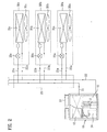
- FIG. 1 illustrates a diagram of a multi-type air conditioner in accordance with a preferred embodiment of the present invention, schematically.
- the multi-type air conditioner includes an outdoor unit 10, a plurality of indoor units 30, and a distributor 20 between the outdoor unit 10, and the indoor units 20.
- the outdoor unit 10 includes a compressor 11, an outdoor heat exchanger 12, an outdoor fan 13, and accumulator 14, and the each of the indoor units 30a, 30b, and 30c includes an indoor heat exchanger 31 a, 31 b, or 31 c, an indoor fan 32a, 32b, or 32c, and an expansion valve 33a, 33b, and 33c.
- the distributor 20 guides the refrigerant from the outdoor unit 10 to the indoor units 30, and vice versa.
- the distributor 20 is connected to the outdoor heat exchanger 12 with a first refrigerant pipe 21, and to the compressor 11 with a second refrigerant pipe.
- the distributor 20 is also connected to the indoor heat exchangers 30a, 30b, and 30c with first branch pipes 21a, 21b, and 21c branched from the first refrigerant pipe 21, and second branch pipes 22a, 22b, and 22c branched from the second refrigerant pipe 22.
- the first branch pipes 21a, 21b, and 21c has expansion valves 33a, 33b, 33c mounted thereon.
- the expansion valves 33a, 33b, and 33c are ordinary LEVs (Linear Expansion Valve).
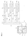
- FIG. 2 illustrates a diagram of a refrigerant flow in a case the multi-type air conditioner of the present invention performs cooling.
- the refrigerant is then introduced into the distributor 20 following the first refrigerant pipe 21, and guided to the expansion valves 33a, 33b, and 33c of respective indoor units 30a, 30b, and 30c following the first branch pipes 21a, 21b, and 21c.
- the refrigerant expands at respective expansion valves 33a, 33b, and 33c, and becomes into low temperature refrigerant.
- the refrigerant is introduced into the indoor heat exchangers 31a, 31b, and 31c, and heat exchanges with room air by the indoor fans 32a, 32b, and 32c, when the room air becomes low temperature air by heat exchange with the refrigerant, and discharged to the room.
- the refrigerant is introduced into the distributor 20 following the second branch pipes 22a, 22b, and 22c, and therefrom to the outdoor unit 10 following the second refrigerant pipe 22.
- the low temperature air is supplied to the room, to cool down the room.
- FIG 3 illustrates a diagram of a refrigerant flow in a case only some of indoor units of a multi-type air conditioner of the present invention perform heating.
- the refrigerant compressed to a high pressure at the compressor 11 is introduced into the distributor 20 through the second refrigerant pipe 22. Then, the refrigerant is introduced into respective indoor units 30a, 30b, and 30c through the second branches 22a, 22b, and 22c.
- the refrigerant introduced into the indoor unit 30a, and 30c heating the rooms is introduced into the indoor heat exchangers 31a, and 31c, and heat exchanges with room air.
- the room air heat exchanged with the refrigerant to be high temperature is discharged to the rooms by the indoor fans 32a, and 32c.
- the refrigerant passes through, and expands at the expansion valves 33a, and 33c, and introduced into the distributor 20 following the first branch pipes 21a, and 21 c. Then, the refrigerant is introduced into the outdoor heat exchanger.12 through the first refrigerant pipe 21, and heat exchanges with outdoor air, and returns to the compressor 11 through the accumulator 14.
- the refrigerant introduced into the turned off indoor unit 30b becomes stagnant at the indoor unit 30b as the expansion valve 33b is closed.
- the refrigerant is stagnant at the indoor heat exchanger 31b and the second pipe 22b, and a part of the first pipe 21b between the expansion valve 33b and the indoor heat exchanger 31b.
- the user controls the multi-type air conditioner, for removing the stagnant refrigerant from the turned off indoor unit 30b.
- Tin denotes a temperature of the refrigerant introduced into the indoor heat exchanger 31b of the turned off indoor unit 30b
- Tout denotes a temperature of the refrigerant discharged from the indoor heat exchanger 31b of the turned off indoor unit 30b.
- FIG. 4 illustrates a flow chart showing the steps of a method for controlling a multi-type air conditioner in accordance with a first preferred embodiment of the present invention
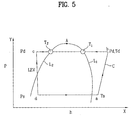
- FIG. 5 illustrates a diagram of a heating cycle on a Mollier chart.
- the method includes the following steps.
- a saturation temperature is define by using a heating cycle of the refrigerant, and the Mollier chart (S11).
- the Mollier chart a pressure-enthalpy diagram, P-h diagram, with enthalpy 'h' on an X-axis and a pressure 'P' on a Y-axis, has a saturated vapor line L1, and a saturated liquid line L2.
- a point at which the saturated vapor line L1 and the saturated liquid line L2 meet is called as a critical point 'A'. Since the Mollier chart is known well, any further description will be omitted.
- the heating cycle 'C' on the Mollier chart represents state changes of the refrigerant circulating the multi-type air conditioner.
- the state changes of the refrigerant moving according to the heating cycle 'C' will be described.
- the refrigerant is compressed to a high temperature Td and high pressure Pd by the compressor 11.
- Td and Pd denote a temperature and a pressure of the refrigerant discharged from the compressor 11.
- a temperature, and a pressure of the refrigerant rise from Ts to Td, and from Ps to Pd, respectively.
- the enthalpy 'h' of the refrigerant also increases according to the increase of the temperature.
- the refrigerant is introduced into the indoor heat exchangers 31 a, and 31c in a b-c section (a condensing section), and heat exchanged with room air, when the refrigerant loses heat, and has enthalpy reduced.
- the refrigerant passes through, and expands at the expansion valves 33a, and 33c in a c-d section (expansion section), to become low pressure Ps refrigerant, and is guided t6 the compressor 11 again through the outdoor heat exchanger 12 in a d-a section (evaporating section).
- the saturation temperature is defined as a temperature T1 or T2 where the heat cycle 'C' of the refrigerant and the Mollier chart meet.
- the saturation temperature T1 or T2 is a refrigerant temperature the b-c section (condensing section) of the heating cycle 'C' and Mollier chart meet. That is, the saturation temperature T1 is a refrigerant temperature at a point where the condensing section of the heating cycle 'C' and the saturated vapor line L1 meet, and the saturation temperature T2 is a refrigerant temperature at a point where the condensing section of the heating cycle 'C' and the saturated liquid line L2 meet.
- the horizontal line connecting the saturated vapor line L1 and the saturated liquid line L2 is an isothermal line. That is, the saturation temperatures T1, and T2 are the same when the refrigerant is pure.
- the saturation temperature T1 and T2 can be obtained by using the Mollier chart and the heating cycle once the pressure Pd of the refrigerant discharged from the compressor 11 is measured.
- the saturation temperature is defined as an average or weighted average of the T1 and T2.
- the average is an arithmetic average [(T1+T2)/2] of the T1 and T2, and the weighted average is a value having a weighted value 'a' added to the average temperature [ ⁇ (T1+T2)/2 ⁇ +a].
- the saturation temperature is defined as either T1 or T2 even in a case the mixed refrigerant is used.
- a temperature of the refrigerant stagnant at the turned off indoor unit 30b is measured (S12).
- the refrigerant temperature is a temperature of the refrigerant in Tin/out Tout of the indoor heat exchanger 31b (see FIG 3). Or, the refrigerant temperature may be an average of the Tin and Tout.
- the refrigerant temperature Tin or Tout can be obtained by measuring a surface temperature of the second branch pipe 22b and a surface temperature of the first branch pipe 21b that connects the expansion valve 33b and the indoor heat exchanger 31b, approximately.
- the expansion valve 33b of the turned off indoor unit 30b is opened, to remove the stagnant refrigerant from the turned off indoor unit 30b (S 14).
- the extent 'A' of opening of the expansion valve is 1 % ⁇ A ⁇ 20%.
- the extent of opening is determined taking a number of the turned off indoor units, or the temperature difference into account, particularly, to minimize noise caused by opening of the expansion valve 33b.
- a noise level of a general residential area is required to be below 65dB in the morning, 70dB during the day, and 55dB during the night, it is verified from experiment that a noise level caused by opened expansion valve can be lower than above noise level, if the extent of opening is 1% ⁇ A ⁇ 20%.
- a temperature range set at the control part may be fixed, or varied with the following parameters.
- the temperature range may be varied with a room temperature.
- the temperature range may be varied with an outdoor temperature.
- the room temperature and the outdoor temperature fix a flow rate of the refrigerant to the indoor unit for heating.
- an amount, and a time period of the refrigerant stagnant at the turned off indoor unit 30b can vary with the room temperature and the outdoor temperature, it is preferable that the room temperature and the outdoor temperature are taken into account in fixing the temperature range.
- the temperature range may vary both with the room temperature and the outdoor temperature.
- the expansion valve of the turned off indoor unit is closed (S15). That is, since the temperature difference being out of the preset temperature range implies that no refrigerant is stagnant at the turned off indoor unit 30b, the expansion valve 33b is closed, to prevent occurrence of the noise in advance.
- Such a feedback control enables realtime monitoring of a state of the turned off indoor unit 30b, and opening/closing of the expansion valve at a proper time, to minimize noise from the multi-type air conditioner caused by unnecessary opening of the expansion valve.
- FIG. 6 illustrates a graph of a refrigerant temperature and an extent of opening of an expansion valve measured at a turned off indoor unit when a multi-type air conditioner is operated by the first preferred embodiment of the present invention.
- the refrigerant temperature Tin/Tout in/out of the indoor heat exchanger 31b keep dropping as time goes by. That is, the refrigerant temperature comes closer to a room temperature Tair as time goes by.
- the temperatures Tin/Tout of the refrigerant in/out of the indoor heat exchanger 31b rise. This implies that, as the expansion valve 33b is opened, low temperature refrigerant is discharged, and new high temperature refrigerant is supplied to the indoor heat exchanger 30b.
- FIG 7 illustrates a flow chart showing the steps of a method for controlling a multi-type air conditioner in accordance with a second preferred embodiment of the present invention.
- the method for controlling a multi-type air conditioner includes the following steps.
- a room temperature is measured (S21). After measuring a temperature of the refrigerant stagnant at the turned off indoor unit 30b (S22), it is determined if a temperature difference of the refrigerant temperature and the room temperature is within a temperature range preset at the control part (S23).
- the expansion valve of the turned off indoor unit is opened (S24), and if the temperature difference is not within the temperature range preset at the control part, the expansion valve of the turned off indoor unit is closed (S25).
- the second embodiment of the present invention is different from the first embodiment of the present invention, in that the second embodiment of the present invention determines opening of the expansion valve, not depending on the saturation temperature, but the room temperature.
- the second embodiment is mostly applicable to a case the indoor units 30a, and 30c that heat the rooms are operated at a low temperature.
- FIG 8 illustrates a flow chart showing the steps of a method for controlling a multi-type air conditioner in accordance with a third preferred embodiment of the present invention.
- the method for controlling a multi-type air conditioner includes the following steps.
- the expansion valve of the turned off indoor unit is opened at a first extent 'B' of opening (S31). It is preferable that the expansion valve 33b is opened after the multi-type air conditioner performs the heating operation for a certain time period.
- the first extent 'B' of opening of the expansion valve is 1% ⁇ B ⁇ 10%.
- the range of the first extent 'B' of opening is determined taking a time period required for removing the refrigerant, and a level of noise occurred into account. That is, if the first extent of opening 'B' is below 1 %, to much time is required for removing the refrigerant, and if the first extent of opening 'B' is over 10%, too loud noise occurs in the heating operation.
- a saturation temperature of the refrigerant is defined by using the heating cycle of the refrigerant, and Mollier chart (S32). Since the saturation temperature is defined In a fashion the same with the first embodiment, no further description will be given.
- a refrigerant temperature stagnant at the turned off indoor unit 30b is measured (S33). Then, it is determined if a temperature difference of the saturation temperature and the refrigerant temperature stagnant at the turned off indoor unit is within a temperature range preset at the control part (S34).
- the refrigerant temperature is a temperature Tin or Tout of the refrigerant in/out of the indoor unit 31b (see FIG. 3). Or, the refrigerant temperature may be an average of the Tin and Tout.
- the refrigerant temperatures Tin and Tout can be obtained by measuring a surface temperature of the second branch pipe 22b and a surface temperature of the first branch pipe 21b connecting the expansion valve 33b and the indoor heat exchanger 31b, approximately.
- the expansion valve 33b of the turned off indoor unit is opened at a second extent of opening 'C' greater than the first extent of opening 'B', and to remove the stagnant refrigerant from the turned off indoor unit (S35).
- the second extent of opening 'C' of the expansion valve 33b is 4% ⁇ C ⁇ 20%.
- the second extent 'C' of opening is determined taking a number of the turned off indoor units, and/or the temperature difference into account, particularly, to minimize noise caused by opening of the expansion valve 33b.
- the temperature range preset at the control part may be fixed, or varied with the following parameters.
- the temperature range may be varied with a room temperature.
- the temperature range may be varied with an outdoor temperature.
- the room temperature and the outdoor temperature fix a flow rate of the refrigerant to the indoor unit for heating.
- an amount, and a time period of the refrigerant stagnant at the turned off indoor unit 30b can vary with the room temperature and the outdoor temperature, it is preferable that the room temperature and the outdoor temperature are taken into account in fixing the temperature range.
- the temperature range may vary both with the room temperature and the outdoor temperature.
- the expansion valve of the turned off indoor unit is opened at. the first extent "B" of opening (S36).
- a feedback control is performed during some of the indoor units perform heating, in which, after the S35 step or the S36 step is performed, steps starting from the S32 step are performed in succession again.
- FIG. 9 illustrates a graph of a refrigerant temperature and an extent of opening of an expansion valve measured at a turned off indoor unit when a multi-type air conditioner is operated by the third preferred embodiment of the present invention.
- the refrigerant temperature Tin/Tout in/out of the indoor heat exchanger 31b keep dropping as time goes by. That is, the refrigerant temperature comes closer to a room temperature Tair as time goes by.
- the expansion valve 33b is in an opened state from the starting at the first extent 'B' of opening in the third embodiment of the present invention, the refrigerant is not liable to be stagnant at the turned off indoor unit 30b, and the refrigerant temperature also drops moderately compared to the first, or second embodiment.
- the third embodiment of the present invention can reduce noise as frequency of opening of the expansion valve 33b is reduced for the same time period.
- FIG 10 illustrates a flow chart showing the steps of a method for controlling a multi-type air conditioner in accordance with a fourth preferred embodiment of the present invention.
- the method for controlling a multi-type air conditioner includes the following steps.
- the expansion valve of the turned off indoor unit is opened at a first extent 'B' of opening (S41). It is preferable that the first extent 'B' of opening of the expansion valve is 1% ⁇ B ⁇ 10%.
- a room temperature is measured (S42). Then, a temperature of the refrigerant stagnant at the turned off indoor unit 30b is measured (S43), and it is determined if a temperature difference of the refrigerant temperature and the room temperature is within a temperature range preset at the control part (S44).
- the expansion valve 33b of the turned off indoor unit is opened to a second extent 'C' of opening greater than the first extent of opening 'B', to remove the stagnant refrigerant from the turned off indoor unit (S45).
- the expansion valve 33b of the turned off indoor unit is opened at the first extent 'B' of opening (S46).
- the fourth embodiment of the present invention is different from the third embodiment in that the fourth embodiment of the present invention determines opening of the expansion valve 33b, not depending on the saturation temperature, but depending on the room temperature. Particularly, the fourth embodiment is mostly used when the indoor units 30a, and 30c that heat the rooms are operated at a low temperature.
- the method for controlling a multi-type air conditioner of the present invention has the following advantages.
- the realtime measurement of the saturation temperature of the refrigerant and the temperature of the refrigerant stagnant at the turned off indoor unit, and opening of the expansion valve according to the measurement permits an operation for removing the stagnant refrigerant from the indoor unit at an appropriate time.
- the minimizing of an amount of refrigerant stagnant at the turned off indoor unit by opening the expansion valve at the first extent of opening permits to increase an opening period of the expansion valve, to reduce noise caused by the opening of the expansion valve.
- the minimizing of refrigerant stagnant at the turned off indoor unit permits to increase an amount of refrigerant circulating through the heating cycle. According to this, the unnecessary temperature rise, and drop of a discharge pressure of the refrigerant discharged from the compressor caused by reduction of circulating refrigerant amount can be reduced.
Landscapes
- Engineering & Computer Science (AREA)
- Physics & Mathematics (AREA)
- Mechanical Engineering (AREA)
- Thermal Sciences (AREA)
- General Engineering & Computer Science (AREA)
- Air Conditioning Control Device (AREA)
- Compression-Type Refrigeration Machines With Reversible Cycles (AREA)
Applications Claiming Priority (2)
| Application Number | Priority Date | Filing Date | Title |
|---|---|---|---|
| KR2004003881 | 2004-01-19 | ||
| KR1020040003881A KR100546616B1 (ko) | 2004-01-19 | 2004-01-19 | 멀티공기조화기의 제어방법 |
Publications (2)
| Publication Number | Publication Date |
|---|---|
| EP1555492A2 true EP1555492A2 (de) | 2005-07-20 |
| EP1555492A3 EP1555492A3 (de) | 2006-06-07 |
Family
ID=34617469
Family Applications (1)
| Application Number | Title | Priority Date | Filing Date |
|---|---|---|---|
| EP04014490A Withdrawn EP1555492A3 (de) | 2004-01-19 | 2004-06-21 | Verfahren zur Steuerung einer multifunktionnellen Klimaanlage |
Country Status (5)
| Country | Link |
|---|---|
| US (1) | US7131283B2 (de) |
| EP (1) | EP1555492A3 (de) |
| JP (1) | JP3977835B2 (de) |
| KR (1) | KR100546616B1 (de) |
| CN (1) | CN100510563C (de) |
Cited By (12)
| Publication number | Priority date | Publication date | Assignee | Title |
|---|---|---|---|---|
| WO2007093175A1 (de) * | 2006-02-13 | 2007-08-23 | Danfoss A/S | Kühlanlage |
| CN100520228C (zh) * | 2005-09-20 | 2009-07-29 | 三洋电机株式会社 | 冷冻系统 |
| EP1998123A4 (de) * | 2006-03-22 | 2011-03-02 | Daikin Ind Ltd | Kühlschrank |
| CN102072587A (zh) * | 2010-11-09 | 2011-05-25 | 刘雄 | 空调制冷设备 |
| EP2375179A4 (de) * | 2010-01-08 | 2013-07-24 | Daikin Ind Ltd | Heizkörper |
| CN103591732A (zh) * | 2013-10-23 | 2014-02-19 | Tcl空调器(中山)有限公司 | 空调系统 |
| EP2835596A4 (de) * | 2012-04-06 | 2016-03-09 | Mitsubishi Heavy Ind Ltd | Steuerungsvorrichtung, verfahren und programm sowie multityp-klimaanlage damit |
| EP2924368A4 (de) * | 2012-11-22 | 2016-07-13 | Mitsubishi Electric Corp | Klimaanlage und betriebssteuerungsverfahren dafür |
| EP3336449A4 (de) * | 2015-08-10 | 2018-06-27 | Mitsubishi Electric Corporation | Multi-klimaanlage |
| EP3537067A1 (de) * | 2018-03-09 | 2019-09-11 | LG Electronics Inc. | Innenraumvorrichtung für klimatisierungssystem und verfahren zur steuerung der vorrichtung |
| EP3647680A4 (de) * | 2017-08-02 | 2020-07-01 | Qingdao Haier Air-Conditioning Electronic Co., Ltd | Verfahren und vorrichtung zur steuerung eines expansionsventils |
| EP3859231A4 (de) * | 2018-09-25 | 2022-05-18 | Toshiba Carrier Corporation | Klimatisierungsvorrichtung |
Families Citing this family (29)
| Publication number | Priority date | Publication date | Assignee | Title |
|---|---|---|---|---|
| KR20060012837A (ko) * | 2004-08-04 | 2006-02-09 | 삼성전자주식회사 | 멀티 에어컨 시스템 및 멀티 에어컨 시스템의 운전방법 |
| KR100701769B1 (ko) * | 2005-10-28 | 2007-03-30 | 엘지전자 주식회사 | 공기조화기의 제어방법 |
| KR100705223B1 (ko) * | 2005-10-28 | 2007-04-06 | 엘지전자 주식회사 | 공기조화기의 부분 과부하 해소방법 |
| KR101376607B1 (ko) * | 2007-02-01 | 2014-03-21 | 엘지전자 주식회사 | 멀티에어컨의 통합관리 시스템 및 제어방법 |
| KR100896996B1 (ko) | 2007-02-02 | 2009-05-14 | 엘지전자 주식회사 | 멀티에어컨의 통합관리 시스템 및 방법 |
| KR100803575B1 (ko) * | 2007-02-02 | 2008-02-15 | 엘지전자 주식회사 | 멀티에어컨의 통합관리 시스템 및 방법 |
| KR20080074378A (ko) * | 2007-02-08 | 2008-08-13 | 엘지전자 주식회사 | 멀티에어컨의 온도제한 방법 |
| KR101160351B1 (ko) | 2007-05-01 | 2012-06-28 | 삼성전자 주식회사 | 멀티 공기조화기 및 그 제어방법 |
| KR101485601B1 (ko) * | 2008-02-25 | 2015-01-28 | 엘지전자 주식회사 | 공기 조화기 및 그의 제어방법 |
| WO2010113296A1 (ja) * | 2009-04-01 | 2010-10-07 | 三菱電機株式会社 | 空気調和装置 |
| KR101505856B1 (ko) * | 2010-09-08 | 2015-03-25 | 삼성전자 주식회사 | 공기조화기 및 그 제어방법 |
| JP5115667B2 (ja) * | 2011-01-17 | 2013-01-09 | ダイキン工業株式会社 | 空気調和機 |
| WO2013156027A1 (en) * | 2012-04-17 | 2013-10-24 | Danfoss A/S | A controller for a vapour compression system and a method for controlling a vapour compression system |
| JP5910610B2 (ja) * | 2013-10-31 | 2016-04-27 | ダイキン工業株式会社 | 空気調和システム |
| CN104697120A (zh) * | 2015-03-24 | 2015-06-10 | 广东美的暖通设备有限公司 | 多联机系统及其的降噪控制方法 |
| CN105650811B (zh) * | 2016-01-04 | 2019-01-08 | 广东美的暖通设备有限公司 | 控制空调室内机的方法和装置 |
| JP6638468B2 (ja) * | 2016-02-29 | 2020-01-29 | 株式会社富士通ゼネラル | 空気調和装置 |
| CN107576108B (zh) * | 2017-08-01 | 2021-09-21 | 青岛海尔空调电子有限公司 | 一种一拖多空调控制方法 |
| CN111219784B (zh) * | 2017-08-29 | 2021-05-04 | 珠海格力电器股份有限公司 | 室内机冷媒控制装置及其控制方法、室内机和空调系统 |
| CN108224689B (zh) * | 2017-12-01 | 2020-11-17 | 青岛海尔空调电子有限公司 | 多联式空调系统的噪音控制方法及控制器 |
| CN108413586B (zh) * | 2018-01-22 | 2020-02-21 | 宁波奥克斯电气股份有限公司 | 多联机的降噪控制方法及多联机 |
| CN110410967B (zh) * | 2019-07-03 | 2021-08-24 | 宁波奥克斯电气股份有限公司 | 多联机空调系统管路噪音的控制方法和多联机空调系统 |
| CN113494764A (zh) * | 2020-04-08 | 2021-10-12 | 广东美的制冷设备有限公司 | 一拖多空调器的控制方法、一拖多空调器及存储介质 |
| CN113639395B (zh) * | 2021-08-05 | 2023-02-28 | 青岛海尔空调电子有限公司 | 多联机空调的控制方法、系统及多联机空调 |
| CN114251776B (zh) * | 2021-12-03 | 2023-03-17 | 珠海格力电器股份有限公司 | 一种关闭新风控制方法、系统、装置、新风机、空调器 |
| JP2024114179A (ja) * | 2023-02-13 | 2024-08-23 | 三菱重工サーマルシステムズ株式会社 | 空調機及び制御方法 |
| CN116734423A (zh) * | 2023-06-07 | 2023-09-12 | 小米科技(武汉)有限公司 | 空调器的控制方法、装置、空调器和存储介质 |
| WO2025150157A1 (ja) * | 2024-01-11 | 2025-07-17 | 三菱電機株式会社 | 空気調和システム、制御装置、および制御方法 |
| CN118794117B (zh) * | 2024-07-23 | 2025-10-28 | Tcl空调器(中山)有限公司 | 空调器及其控制方法、装置、计算机可读存储介质 |
Family Cites Families (18)
| Publication number | Priority date | Publication date | Assignee | Title |
|---|---|---|---|---|
| JPS60134227A (ja) | 1983-12-23 | 1985-07-17 | Asahi Optical Co Ltd | スリツト露光型変倍複写機の露光量制御装置 |
| JPS6243269A (ja) | 1985-08-20 | 1987-02-25 | Victor Co Of Japan Ltd | 水平偏向直線性補正装置 |
| JPS6249146A (ja) | 1985-08-29 | 1987-03-03 | Mitsubishi Electric Corp | 多室形空気調和機 |
| JPS6243269U (de) * | 1985-09-02 | 1987-03-16 | ||
| JPS62288441A (ja) | 1986-06-06 | 1987-12-15 | Mitsubishi Electric Corp | 多室用空気調和機 |
| JPH02282664A (ja) | 1989-04-24 | 1990-11-20 | Matsushita Seiko Co Ltd | 多室形空気調和機の電動膨張弁制御装置 |
| JP2836176B2 (ja) | 1990-03-31 | 1998-12-14 | アイシン精機株式会社 | エンジン駆動式空気調和機 |
| JPH04198672A (ja) * | 1990-11-28 | 1992-07-20 | Matsushita Seiko Co Ltd | 多室形空気調和機の電動膨張弁制御装置 |
| JPH05248722A (ja) * | 1992-03-05 | 1993-09-24 | Matsushita Seiko Co Ltd | 多室形空気調和機の冷媒制御装置 |
| CN1041555C (zh) * | 1992-09-26 | 1999-01-06 | 三洋电机株式会社 | 空气调节器的控制方法 |
| EP0959308B1 (de) * | 1993-11-12 | 2004-11-03 | SANYO ELECTRIC Co., Ltd. | Klimaanlage |
| JP3573868B2 (ja) * | 1996-02-26 | 2004-10-06 | 三洋電機株式会社 | 空気調和機の運転制御方法 |
| JPH09280681A (ja) | 1996-04-17 | 1997-10-31 | Matsushita Electric Ind Co Ltd | 空気調和機 |
| JPH10157449A (ja) * | 1996-11-28 | 1998-06-16 | Denso Corp | 冷凍サイクル装置 |
| JPH11173628A (ja) | 1997-12-15 | 1999-07-02 | Mitsubishi Heavy Ind Ltd | 空気調和装置 |
| JP3736969B2 (ja) * | 1998-05-20 | 2006-01-18 | 三菱電機株式会社 | 空気調和機 |
| JP3835310B2 (ja) * | 2002-03-04 | 2006-10-18 | 株式会社日立製作所 | 空気調和機 |
| KR20060012837A (ko) * | 2004-08-04 | 2006-02-09 | 삼성전자주식회사 | 멀티 에어컨 시스템 및 멀티 에어컨 시스템의 운전방법 |
-
2004
- 2004-01-19 KR KR1020040003881A patent/KR100546616B1/ko not_active Expired - Fee Related
- 2004-06-21 EP EP04014490A patent/EP1555492A3/de not_active Withdrawn
- 2004-06-30 US US10/879,202 patent/US7131283B2/en not_active Expired - Lifetime
- 2004-10-29 JP JP2004316678A patent/JP3977835B2/ja not_active Expired - Fee Related
- 2004-11-24 CN CNB200410095355XA patent/CN100510563C/zh not_active Expired - Fee Related
Non-Patent Citations (1)
| Title |
|---|
| None * |
Cited By (15)
| Publication number | Priority date | Publication date | Assignee | Title |
|---|---|---|---|---|
| CN100520228C (zh) * | 2005-09-20 | 2009-07-29 | 三洋电机株式会社 | 冷冻系统 |
| WO2007093175A1 (de) * | 2006-02-13 | 2007-08-23 | Danfoss A/S | Kühlanlage |
| US8191384B2 (en) | 2006-02-13 | 2012-06-05 | Danfoss A/S | Refrigeration system |
| EP1998123A4 (de) * | 2006-03-22 | 2011-03-02 | Daikin Ind Ltd | Kühlschrank |
| EP2375179A4 (de) * | 2010-01-08 | 2013-07-24 | Daikin Ind Ltd | Heizkörper |
| CN102072587A (zh) * | 2010-11-09 | 2011-05-25 | 刘雄 | 空调制冷设备 |
| CN102072587B (zh) * | 2010-11-09 | 2012-07-04 | 刘雄 | 空调制冷设备 |
| EP2835596A4 (de) * | 2012-04-06 | 2016-03-09 | Mitsubishi Heavy Ind Ltd | Steuerungsvorrichtung, verfahren und programm sowie multityp-klimaanlage damit |
| EP2924368A4 (de) * | 2012-11-22 | 2016-07-13 | Mitsubishi Electric Corp | Klimaanlage und betriebssteuerungsverfahren dafür |
| CN103591732A (zh) * | 2013-10-23 | 2014-02-19 | Tcl空调器(中山)有限公司 | 空调系统 |
| CN103591732B (zh) * | 2013-10-23 | 2016-08-17 | Tcl空调器(中山)有限公司 | 空调系统 |
| EP3336449A4 (de) * | 2015-08-10 | 2018-06-27 | Mitsubishi Electric Corporation | Multi-klimaanlage |
| EP3647680A4 (de) * | 2017-08-02 | 2020-07-01 | Qingdao Haier Air-Conditioning Electronic Co., Ltd | Verfahren und vorrichtung zur steuerung eines expansionsventils |
| EP3537067A1 (de) * | 2018-03-09 | 2019-09-11 | LG Electronics Inc. | Innenraumvorrichtung für klimatisierungssystem und verfahren zur steuerung der vorrichtung |
| EP3859231A4 (de) * | 2018-09-25 | 2022-05-18 | Toshiba Carrier Corporation | Klimatisierungsvorrichtung |
Also Published As
| Publication number | Publication date |
|---|---|
| EP1555492A3 (de) | 2006-06-07 |
| JP2005207722A (ja) | 2005-08-04 |
| KR100546616B1 (ko) | 2006-01-26 |
| CN1645007A (zh) | 2005-07-27 |
| CN100510563C (zh) | 2009-07-08 |
| US7131283B2 (en) | 2006-11-07 |
| KR20050076080A (ko) | 2005-07-26 |
| US20050155368A1 (en) | 2005-07-21 |
| JP3977835B2 (ja) | 2007-09-19 |
Similar Documents
| Publication | Publication Date | Title |
|---|---|---|
| EP1555492A2 (de) | Verfahren zur Steuerung einer multifunktionnellen Klimaanlage | |
| JP6652219B1 (ja) | 冷媒漏洩判定システム及び冷凍サイクル装置 | |
| JP5063346B2 (ja) | 冷媒漏洩検知機能を有した冷凍空調システム、冷凍空調装置および冷媒漏洩検知方法 | |
| JP4215022B2 (ja) | 空気調和装置 | |
| WO2005121664A1 (ja) | 空気調和装置 | |
| KR20080081946A (ko) | 공기 조화 장치 | |
| CN101331366A (zh) | 空调装置 | |
| US7137265B2 (en) | Apparatus and method for controlling oil of air conditioner | |
| US12181168B2 (en) | Air conditioner and control method thereof | |
| CN113432264A (zh) | 冷媒循环系统和控制空调器除湿的方法及空调器 | |
| CN113432261A (zh) | 冷媒循环系统和控制空调器除湿的方法及空调器 | |
| US7185502B2 (en) | Multi-type air conditioner and method for controlling operation of the same | |
| JP4826117B2 (ja) | 冷媒漏洩検知システム | |
| WO2020111241A1 (ja) | 冷凍サイクル装置及び冷凍サイクルシステム | |
| JP5245576B2 (ja) | 空気調和装置の冷媒量判定方法および空気調和装置 | |
| EP1970654A1 (de) | Klimaanlage | |
| JP5245575B2 (ja) | 空気調和装置の冷媒量判定方法および空気調和装置 | |
| EP3943841A1 (de) | Klimatisierungssystem | |
| US7467521B2 (en) | Method for controlling multi-type air conditioner | |
| CN118776076A (zh) | 一种多联机空调系统及其控制方法 | |
| JP2006292214A (ja) | 空気調和装置の冷媒量判定機能追加方法、及び、空気調和装置 | |
| KR20100116891A (ko) | 공기조화기의 제상운전방법 | |
| JP7749147B1 (ja) | 冷凍サイクル装置 | |
| JP7657096B2 (ja) | 冷凍サイクル装置および冷媒漏洩判定システム | |
| CN112303814B (zh) | 一种空调及空调化霜方法 |
Legal Events
| Date | Code | Title | Description |
|---|---|---|---|
| PUAI | Public reference made under article 153(3) epc to a published international application that has entered the european phase |
Free format text: ORIGINAL CODE: 0009012 |
|
| 17P | Request for examination filed |
Effective date: 20040621 |
|
| AK | Designated contracting states |
Kind code of ref document: A2 Designated state(s): AT BE BG CH CY CZ DE DK EE ES FI FR GB GR HU IE IT LI LU MC NL PL PT RO SE SI SK TR |
|
| AX | Request for extension of the european patent |
Extension state: AL HR LT LV MK |
|
| PUAL | Search report despatched |
Free format text: ORIGINAL CODE: 0009013 |
|
| AK | Designated contracting states |
Kind code of ref document: A3 Designated state(s): AT BE BG CH CY CZ DE DK EE ES FI FR GB GR HU IE IT LI LU MC NL PL PT RO SE SI SK TR |
|
| AX | Request for extension of the european patent |
Extension state: AL HR LT LV MK |
|
| AKX | Designation fees paid |
Designated state(s): DE FR GB IT |
|
| 17Q | First examination report despatched |
Effective date: 20110509 |
|
| RIC1 | Information provided on ipc code assigned before grant |
Ipc: F25B 13/00 20060101AFI20170920BHEP Ipc: F25B 49/02 20060101ALI20170920BHEP |
|
| GRAP | Despatch of communication of intention to grant a patent |
Free format text: ORIGINAL CODE: EPIDOSNIGR1 |
|
| INTG | Intention to grant announced |
Effective date: 20171102 |
|
| STAA | Information on the status of an ep patent application or granted ep patent |
Free format text: STATUS: THE APPLICATION IS DEEMED TO BE WITHDRAWN |
|
| 18D | Application deemed to be withdrawn |
Effective date: 20180313 |
|
| RIC1 | Information provided on ipc code assigned before grant |
Ipc: F25B 13/00 20060101AFI20170920BHEP Ipc: F25B 49/02 20060101ALI20170920BHEP |