EP1555374A1 - Riegelwerk für Wertbehältnisse - Google Patents
Riegelwerk für Wertbehältnisse Download PDFInfo
- Publication number
- EP1555374A1 EP1555374A1 EP05000032A EP05000032A EP1555374A1 EP 1555374 A1 EP1555374 A1 EP 1555374A1 EP 05000032 A EP05000032 A EP 05000032A EP 05000032 A EP05000032 A EP 05000032A EP 1555374 A1 EP1555374 A1 EP 1555374A1
- Authority
- EP
- European Patent Office
- Prior art keywords
- bolt
- main
- main bolt
- bar
- disc
- Prior art date
- Legal status (The legal status is an assumption and is not a legal conclusion. Google has not performed a legal analysis and makes no representation as to the accuracy of the status listed.)
- Granted
Links
- 239000000463 material Substances 0.000 claims abstract description 5
- 239000002184 metal Substances 0.000 claims description 5
- 238000006073 displacement reaction Methods 0.000 claims description 2
- 230000009172 bursting Effects 0.000 claims 1
- 239000011521 glass Substances 0.000 description 7
- 239000003795 chemical substances by application Substances 0.000 description 3
- 238000010276 construction Methods 0.000 description 2
- 238000004519 manufacturing process Methods 0.000 description 2
- 239000013543 active substance Substances 0.000 description 1
- 230000015572 biosynthetic process Effects 0.000 description 1
- 238000005336 cracking Methods 0.000 description 1
- 238000005553 drilling Methods 0.000 description 1
- 230000003116 impacting effect Effects 0.000 description 1
- 230000007306 turnover Effects 0.000 description 1
Images



Classifications
-
- E—FIXED CONSTRUCTIONS
- E05—LOCKS; KEYS; WINDOW OR DOOR FITTINGS; SAFES
- E05B—LOCKS; ACCESSORIES THEREFOR; HANDCUFFS
- E05B65/00—Locks or fastenings for special use
- E05B65/0075—Locks or fastenings for special use for safes, strongrooms, vaults, fire-resisting cabinets or the like
- E05B65/0082—Locks or fastenings for special use for safes, strongrooms, vaults, fire-resisting cabinets or the like with additional locking responsive to attack, e.g. to heat, explosion
-
- E—FIXED CONSTRUCTIONS
- E05—LOCKS; KEYS; WINDOW OR DOOR FITTINGS; SAFES
- E05C—BOLTS OR FASTENING DEVICES FOR WINGS, SPECIALLY FOR DOORS OR WINDOWS
- E05C19/00—Other devices specially designed for securing wings, e.g. with suction cups
- E05C19/001—Other devices specially designed for securing wings, e.g. with suction cups with bolts extending over a considerable extent, e.g. nearly along the whole length of at least one side of the wing
-
- E—FIXED CONSTRUCTIONS
- E05—LOCKS; KEYS; WINDOW OR DOOR FITTINGS; SAFES
- E05G—SAFES OR STRONG-ROOMS FOR VALUABLES; BANK PROTECTION DEVICES; SAFETY TRANSACTION PARTITIONS
- E05G1/00—Safes or strong-rooms for valuables
- E05G1/02—Details
- E05G1/04—Closure fasteners
Definitions
- the invention relates to a bolt work for safes, such as cash dispensers, automatic cash vaults or the like according to the preamble of the claim 1.
- Such bolt works are known in various embodiments, e.g. from DE 201 16 334 U1.
- the bolt work disclosed in this document has one slidable main latch, which is lockable with the help of a lock.
- the Main bolt is assigned to an emergency locking device, which in a burglary attempt the opening movements of the main bolt locks.
- This emergency locking device has emergency locking pieces by at least one spring stretched against each other and e.g. about guide pins in a fragile one Material such as glass are positioned on existing pane. If the glass is at destroyed a burglary attempt, the emergency locking pieces with the help of a Spring moved to a locking position in which they set the main bolt and secure against shifting.
- the main bar is associated with an emergency hammer, the wholly or partially directed in the stroke direction of the main bolt strikes the fragile Impacting disk with great force.
- Intrusion attempts are activated, are in the main bolt deformation recesses mounted, in the event of a strike on a tie bar connected to the main bar deformed and thereby a shift of the bolt bar in the direction of Cause main bar. This shift activates the hammer and causes it to strike the disc.
- the disc Since the agents lie directly on the disc or only slightly spaced from the disc are positioned, the disc is at a force on the agents, which leads to a displacement of the active agent, pressed and burst.
- the design effort is very low, since no hinge construction as needed with a hammer.
- a high level of functional reliability is ensured because the disc in a stroke on the main bar in the stroke direction every case is destroyed.
- the device for Destroy the disc at least one of the main latch associated tab, which extends from the main bolt towards the disk.
- This reliable variant requires no component except the tab on the main bolt and is therefore particularly cost.
- the main bolt is made of a metal sheet and the tab in particularly simple way bent directly out of the metal sheet of the main bolt.
- the device for destroying the disc has at least one or more Ball (s) on which at least one hole in the main bolt - and preferably in the base plate - interspersed and which in a break-in attempt from the main bar is pressed in the direction of the disc.
- Ball s
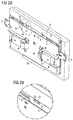
- a bolt mechanism 1 for a door 2 of one here is also otherwise not shown, the bolt works 1 a base plate 3 and a cover plate 4 parallel thereto, between which a main bolt 5 of a metal sheet and two optionally providable baskulungskangen 6, 7 (see Also Fig. 2a) are guided displaceably.
- the Baskulestangen 6, 7 are with the Main latch 5 coupled via a not shown here gear and orthogonal to Main bar 5 toward each other and away from each other movable. In their locking position grab the main bar 5 and the Baskulestangen 6, 7 each in tie bars one of which only the bolt bar 8 is shown here for the main bolt 5.
- the Main latch 5 is next to a lock S (Fig. 2) an emergency locking device assigned, which in a break-in attempt a possible opening movement of the main bolt 5 locks.
- This emergency locking device has emergency locking pieces 9, which in the Normal position on here not shown guide pins in a fragile Material like glass existing disc 11 intervene.
- When opening the main bolt 5 grab these emergency locking pieces 9 in recesses 10 of the main latch 5 a.
- the glass pane 11 and a spring shatter here also not shown is activated and moved during the cracking of the glass plate 11 its associated emergency locking piece in a locked position -. locking against an area of the main bolt 5.
- the main bolt 5 is a device assigned to destroy the disc 11.
- this includes at least one tab 12, which directly from the material of the main bolt 5 is punched out and bent so that they still on one of their sides with the main bolt 5 is connected.
- the tab 12 is out of the plane of the main bolt. 5 down in the direction of the disc 11 so bent that they are very close to the disc 11 comes up.
- the tab 12 is positioned in the main bar 5 so that it is in the Locking position of the main latch 5 (Fig. 1a) to all or near the bolt bar 8 for the main bar 5 comes up.
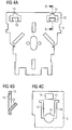
- the - preferably two - tabs 12 in Figs. 1 and Fig. 4a, b are the - preferably two - tabs 12 in Figs. 1 and Fig. 4a, b to recognize.
- Above the tabs 12 is in each case a recess 15 in Main bar 5, via which the main bolt 5 is coupled to the bolt bar 8.
- the bolt bar 8 has a slot 8a, in which the main bolt 5 engages. about not shown pins or bolts is the main bolt 5 on the recesses 15 integrally connected to the locking bar 8.
- the locking bar 8 is opened and closing together with the main bolt 5 moves.
- the bolt bar 8 is here designed such that between the end of the main bolt 5 and the base of the slot 8a forms a gap D when the main latch 5 engages.
- the bolt bar 8 is therefore arranged and designed so that they more than the amount of the gap D in the direction of the main bolt 5 is displaceable. Through this Movement pushes the locking bar 8 against the tab 12 so that they still something is bent further in the direction of the disc 11. In this case, the disc 11 is pressed and shatters. As a result, solve the emergency locking pieces 9, so that move them into their emergency locking position and thus the main latch 5 against additionally secure a violent opening.
- This solution has the advantage of being different as a hinged hammer, which strikes the disc 11, do not jam can. It also has the additional advantage that it is possible to use the Limit force to trigger the emergency locking device to dimension small.
- a ball 13 for destroying the disc 11 is used.
- the ball 13 passes through two with each other aligned bores 14a, b in the base plate 3 and the main bar 5 and lies directly on the disc 11.
- Above the Hole 14 a in the main bolt 5 is a recess 15.
- pins or bolts is the main bar 5 turn over the recesses 15 integrally connected to the locking bar 8.
- the locking bar 8 is opened and closing together with the main bolt 5 moves.
- the bolt bar 8 is here designed such that between the end of the main bolt 5 and the base of the slot 8a forms a gap D when the main latch 5 engages.
- two slots 16 connect here, which in the plate of the main latch 5 to just before the recess 15 for the pins or bolts of the locking bar 8 extend, so that between the recess 15 and the slots 16 each only thin webs 17 remain and between the slots 16 forms a tab 19.
Landscapes
- Connection Of Plates (AREA)
- Lock And Its Accessories (AREA)
- Burglar Alarm Systems (AREA)
- Emergency Lowering Means (AREA)
Abstract
Description
- Fig. 1a
- eine Schnittansicht eines ersten Ausführungsbeispiels des erfindungsgemäßen Riegelwerks;
- Fig. 1b
- eine Ausschnittsvergrößerung des Bereiches A aus Fig. 1;
- Fig. 2a
- eine perspektivische Ansicht des Ausführungsbeispiels aus Fig. 1;
- Fig. 2b
- eine Ausschnittsvergrößerung des Bereiches B aus Fig. 2;
- Fig. 3a-g
- verschiedene Ansichten und Ausschnittsvergrößerungen eines weiteren Ausführungsbeispiels der Erfindung;
- Fig. 4a,b
- eine Draufsicht auf den Hauptriegel aus Fig. 1 sowie einen Schnitt des Bereiches A-A aus Fig. 4a;
- Fig. 4c
- eine Draufsicht auf einen Teil des Hauptriegels des Ausführungsbeispiels der Fig. 3f.
- Riegelwerk
- 1
- Tür
- 2
- Grundplatte
- 3
- Deckplatte
- 4
- Hauptriegel
- 5
- Baskulestangen
- 6, 7
- Riegelleiste
- 8
- Notverriegelungsstücke
- 9
- Ausnehmungen
- 10
- Scheibe
- 11
- Lasche
- 12
- Kugel
- 13
- Bohrungen
- 14
- Ausnehmungen
- 15
- Schlitze
- 16
- Stege
- 17
- Ringscheibe
- 18
- Lasche
- 19
- Schloss
- S
- Widerlagerträger
- W
Claims (8)
- Riegelwerk (1) für eine Tür (2) eines Wertbehältnisses, mitdadurch gekennzeichnet, dasseiner Grundplatte (3), auf welcher ein Hauptriegel (5) verschieblich geführt ist und mit dem die Tür ver- und entriegelbar ist,einer Riegelleiste (8), die mit dem Hauptriegel (5) einstückig verbunden ist,eine Notverriegelungseinrichtung, welche bei einem Einbruchsversuch die Öffnungsbewegungen des Hauptriegels (5) sperrt, und die in eine aus einem zerbrechlichen Material bestehende Scheibe (11) eingreifende Notverriegelungsstücke (9) aufweist, die bei einem bei einem Zerspringen der Scheibe (11) infolge eines Einbruchsversuchs in eine Verriegelungsstellung bewegbar ist, in welcher sie den Hauptriegel (5) gegen ein Verschieben sichern,eine Einrichtung zum Zerstören der Scheibe (11) im Falle eines Einbruchsversuchs,
die Einrichtung zum Zerstören der Scheibe (11) Einwirkmittel umfasst, die auf der Scheibe (11) aufliegen oder nur gering von der Scheibe (11) beabstandet sind, wobei bei einem Schlag auf die Riegelleiste (8) die Einwirkmittel verschoben werden und die Scheibe (11) eindrücken. - Riegelwerk nach Anspruch 1, dadurch gekennzeichnet, dass Einwirkmittel als Lasche (12) ausgebildet ist, welche unterhalb einer Ausnehmung (15) im Hauptriegel (5) angeordnet ist und sich vom Hauptriegel (5) in Richtung der Scheibe (11) erstreckt.
- Riegelwerk nach Anspruch 2, dadurch gekennzeichnet, dass der Hauptriegel (5) aus einem Metallblech gefertigt ist und dass die Lasche (12) aus dem Metallblech des Hauptriegels (5) herausgebogen ist.
- Riegelwerk nach Anspruch 2 oder 3, dadurch gekennzeichnet, dass sich die Lasche (12) in Richtung der Riegelleiste (8) erstreckt.
- Riegelwerk nach Anspruch 1, dadurch gekennzeichnet, dass die Einwirkmittel als Kugel (13) ausgebildet ist, welche zumindest eine Bohrung (14) im Hauptriegel (5) durchsetzt.
- Riegelwerk nach Anspruch 5, dadurch gekennzeichnet, dass der Hauptriegel (5) und die Grundplatte (3) miteinander fluchtende Bohrungen (14a, 14b) aufweisen, in welchen die Kugel (13) gehaltert ist.
- Riegelwerk nach einem der vorstehenden Ansprüche, dadurch gekennzeichnet, dass sich am Außenumfang der Bohrung (14) für die Kugel (13) Schlitze (16) im Hauptriegel (5) anschließen, die sich in Richtung der Ausnehmung (15) erstrecken und eine Lasche (19) ausbilden, die auf die Kugel (13) einwirken kann.
- Riegelwerk nach einem der vorstehenden Ansprüche, dadurch gekennzeichnet, dass zwischen der Ausnehmung (15) und den Schlitzen (16) Stege (17) ausgebildet sind.
Applications Claiming Priority (2)
| Application Number | Priority Date | Filing Date | Title |
|---|---|---|---|
| DE102004002354 | 2004-01-15 | ||
| DE102004002354 | 2004-01-15 |
Publications (2)
| Publication Number | Publication Date |
|---|---|
| EP1555374A1 true EP1555374A1 (de) | 2005-07-20 |
| EP1555374B1 EP1555374B1 (de) | 2007-08-15 |
Family
ID=34609587
Family Applications (1)
| Application Number | Title | Priority Date | Filing Date |
|---|---|---|---|
| EP20050000032 Expired - Lifetime EP1555374B1 (de) | 2004-01-15 | 2005-01-04 | Riegelwerk für Wertbehältnisse |
Country Status (3)
| Country | Link |
|---|---|
| EP (1) | EP1555374B1 (de) |
| DE (2) | DE502005001200D1 (de) |
| ES (1) | ES2289604T3 (de) |
Cited By (2)
| Publication number | Priority date | Publication date | Assignee | Title |
|---|---|---|---|---|
| WO2008145961A3 (en) * | 2007-06-01 | 2009-12-17 | Cedardell Limited | Security assembly and method of controlling a security assembly |
| EP2647788A1 (de) * | 2012-04-05 | 2013-10-09 | Nautilus Hyosung Inc. | Verriegelungsvorrichtung einer Tür |
Families Citing this family (4)
| Publication number | Priority date | Publication date | Assignee | Title |
|---|---|---|---|---|
| DE102008052183A1 (de) * | 2008-10-17 | 2010-04-22 | Wincor Nixdorf International Gmbh | Verriegelungsvorrichtung für Wertbehälter |
| DE102012024864B4 (de) * | 2011-12-20 | 2021-07-08 | Atec Ap Co., Ltd. | Türverriegelungsvorrichtung |
| DE102013014562B3 (de) * | 2013-08-31 | 2015-03-05 | Kaba Mauer Gmbh | Sicherheitsverriegelung für eine Tresortür |
| DE202022101449U1 (de) | 2022-03-18 | 2023-06-20 | Burg-Wächter Kg | Riegel und Riegeleinrichtung |
Citations (4)
| Publication number | Priority date | Publication date | Assignee | Title |
|---|---|---|---|---|
| EP0058218A1 (de) * | 1981-02-13 | 1982-08-25 | Erwin Drescher | Verschluss für einen Tresor |
| DE20106223U1 (de) * | 2001-04-09 | 2001-07-12 | Carl Wittkopp-Gmbh & Co Kg, 42551 Velbert | Riegelwerk für Wertbehältnisse |
| DE20116334U1 (de) * | 2001-10-05 | 2001-12-20 | Carl Wittkopp-Gmbh & Co Kg, 42551 Velbert | Riegelwerk für Wertbehältnisse |
| EP1288423A1 (de) * | 2001-09-03 | 2003-03-05 | Kaba Mauer GmbH | Riegelwerk für eine Tresortür |
-
2005
- 2005-01-04 ES ES05000032T patent/ES2289604T3/es not_active Expired - Lifetime
- 2005-01-04 EP EP20050000032 patent/EP1555374B1/de not_active Expired - Lifetime
- 2005-01-04 DE DE200550001200 patent/DE502005001200D1/de not_active Expired - Lifetime
- 2005-01-11 DE DE102005001355A patent/DE102005001355B4/de not_active Expired - Lifetime
Patent Citations (4)
| Publication number | Priority date | Publication date | Assignee | Title |
|---|---|---|---|---|
| EP0058218A1 (de) * | 1981-02-13 | 1982-08-25 | Erwin Drescher | Verschluss für einen Tresor |
| DE20106223U1 (de) * | 2001-04-09 | 2001-07-12 | Carl Wittkopp-Gmbh & Co Kg, 42551 Velbert | Riegelwerk für Wertbehältnisse |
| EP1288423A1 (de) * | 2001-09-03 | 2003-03-05 | Kaba Mauer GmbH | Riegelwerk für eine Tresortür |
| DE20116334U1 (de) * | 2001-10-05 | 2001-12-20 | Carl Wittkopp-Gmbh & Co Kg, 42551 Velbert | Riegelwerk für Wertbehältnisse |
Cited By (4)
| Publication number | Priority date | Publication date | Assignee | Title |
|---|---|---|---|---|
| WO2008145961A3 (en) * | 2007-06-01 | 2009-12-17 | Cedardell Limited | Security assembly and method of controlling a security assembly |
| JP2010529330A (ja) * | 2007-06-01 | 2010-08-26 | セダーデル リミテッド | セキュリティ組立体およびセキュリティ組立体の制御方法 |
| US8443737B2 (en) | 2007-06-01 | 2013-05-21 | Robert Edmund Todd | Security assembly and method of controlling a security assembly |
| EP2647788A1 (de) * | 2012-04-05 | 2013-10-09 | Nautilus Hyosung Inc. | Verriegelungsvorrichtung einer Tür |
Also Published As
| Publication number | Publication date |
|---|---|
| EP1555374B1 (de) | 2007-08-15 |
| DE502005001200D1 (de) | 2007-09-27 |
| DE102005001355A1 (de) | 2005-08-11 |
| ES2289604T3 (es) | 2008-02-01 |
| DE102005001355B4 (de) | 2008-04-17 |
Similar Documents
| Publication | Publication Date | Title |
|---|---|---|
| DE69830813T2 (de) | Kraftwagentürscharnier | |
| EP1555374B1 (de) | Riegelwerk für Wertbehältnisse | |
| DE19632318A1 (de) | Verriegelungsvorrichtung für Schacht-Innendeckel | |
| DE20116334U1 (de) | Riegelwerk für Wertbehältnisse | |
| DE69405511T2 (de) | Türschloss mit Schutzeinrichtung | |
| EP3516135B1 (de) | Beschlag | |
| DE68913918T2 (de) | Schutzvorrichtung für Zylinderschlösser. | |
| EP0957219A1 (de) | Steckzylinderschloss, insbesondere zur Verwendung an Schutzvorrichtungen für Spiel- und Warenautomaten | |
| EP1164246A2 (de) | Riegelwerk für eine Tresortür | |
| EP0808970B1 (de) | Zylinderschloss | |
| DE29502983U1 (de) | Sicherheitsschloßantiaufbruchvorrichtung mit Not- oder Zusatzriegel | |
| DE29803010U1 (de) | Gehäuse für einen selbstkassierenden Warenverkaufs- oder Dienstleistungsautomaten | |
| DE102018123427A1 (de) | Riegelschloss | |
| EP1288423B1 (de) | Riegelwerk für eine Tresortür | |
| EP0972896B1 (de) | Schliesszylinder | |
| DE102009029020B4 (de) | Drehfalle für Kraftfahrzeugschloss | |
| EP1317595B1 (de) | Schliesssystem für gehäuse | |
| WO2001061130A1 (de) | Schliesssystem, insbesondere für kfz | |
| EP0058218A1 (de) | Verschluss für einen Tresor | |
| EP0589209A2 (de) | Zylinderschloss | |
| EP3363970B1 (de) | Schloss | |
| DE102010011427A1 (de) | Sicherungsanordnung für Schiebetüren | |
| DE2914376C2 (de) | Zweiflügelige Tür mit Schloß-Einstecktaschen | |
| EP0927801A1 (de) | Schliesszylinder für ein Sicherheitsschloss | |
| EP4646519A1 (de) | Schlüssel und drehschliesszylinder mit schlüssel |
Legal Events
| Date | Code | Title | Description |
|---|---|---|---|
| PUAI | Public reference made under article 153(3) epc to a published international application that has entered the european phase |
Free format text: ORIGINAL CODE: 0009012 |
|
| AK | Designated contracting states |
Kind code of ref document: A1 Designated state(s): AT BE BG CH CY CZ DE DK EE ES FI FR GB GR HU IE IS IT LI LT LU MC NL PL PT RO SE SI SK TR |
|
| AX | Request for extension of the european patent |
Extension state: AL BA HR LV MK YU |
|
| 17P | Request for examination filed |
Effective date: 20050705 |
|
| AKX | Designation fees paid |
Designated state(s): DE ES FR GB IT RO |
|
| GRAP | Despatch of communication of intention to grant a patent |
Free format text: ORIGINAL CODE: EPIDOSNIGR1 |
|
| GRAS | Grant fee paid |
Free format text: ORIGINAL CODE: EPIDOSNIGR3 |
|
| GRAA | (expected) grant |
Free format text: ORIGINAL CODE: 0009210 |
|
| AK | Designated contracting states |
Kind code of ref document: B1 Designated state(s): DE ES FR GB IT RO |
|
| REG | Reference to a national code |
Ref country code: GB Ref legal event code: FG4D Free format text: NOT ENGLISH |
|
| REF | Corresponds to: |
Ref document number: 502005001200 Country of ref document: DE Date of ref document: 20070927 Kind code of ref document: P |
|
| REG | Reference to a national code |
Ref country code: RO Ref legal event code: EPE |
|
| ET | Fr: translation filed | ||
| GBT | Gb: translation of ep patent filed (gb section 77(6)(a)/1977) |
Effective date: 20071112 |
|
| REG | Reference to a national code |
Ref country code: ES Ref legal event code: FG2A Ref document number: 2289604 Country of ref document: ES Kind code of ref document: T3 |
|
| PLBE | No opposition filed within time limit |
Free format text: ORIGINAL CODE: 0009261 |
|
| STAA | Information on the status of an ep patent application or granted ep patent |
Free format text: STATUS: NO OPPOSITION FILED WITHIN TIME LIMIT |
|
| 26N | No opposition filed |
Effective date: 20080516 |
|
| REG | Reference to a national code |
Ref country code: FR Ref legal event code: PLFP Year of fee payment: 12 |
|
| REG | Reference to a national code |
Ref country code: FR Ref legal event code: PLFP Year of fee payment: 13 |
|
| REG | Reference to a national code |
Ref country code: FR Ref legal event code: PLFP Year of fee payment: 14 |
|
| REG | Reference to a national code |
Ref country code: FR Ref legal event code: PLFP Year of fee payment: 19 |
|
| REG | Reference to a national code |
Ref country code: GB Ref legal event code: 732E Free format text: REGISTERED BETWEEN 20230316 AND 20230322 |
|
| REG | Reference to a national code |
Ref country code: GB Ref legal event code: 732E Free format text: REGISTERED BETWEEN 20230525 AND 20230601 |
|
| REG | Reference to a national code |
Ref country code: DE Ref legal event code: R081 Ref document number: 502005001200 Country of ref document: DE Owner name: DIEBOLD NIXDORF SYSTEMS GMBH, DE Free format text: FORMER OWNER: WINCOR NIXDORF INTERNATIONAL GMBH, 33106 PADERBORN, DE |
|
| PGFP | Annual fee paid to national office [announced via postgrant information from national office to epo] |
Ref country code: GB Payment date: 20231219 Year of fee payment: 20 |
|
| PGFP | Annual fee paid to national office [announced via postgrant information from national office to epo] |
Ref country code: RO Payment date: 20231229 Year of fee payment: 20 Ref country code: FR Payment date: 20231219 Year of fee payment: 20 |
|
| PGFP | Annual fee paid to national office [announced via postgrant information from national office to epo] |
Ref country code: ES Payment date: 20240202 Year of fee payment: 20 |
|
| PGFP | Annual fee paid to national office [announced via postgrant information from national office to epo] |
Ref country code: DE Payment date: 20231219 Year of fee payment: 20 |
|
| PGFP | Annual fee paid to national office [announced via postgrant information from national office to epo] |
Ref country code: IT Payment date: 20240102 Year of fee payment: 20 |
|
| REG | Reference to a national code |
Ref country code: DE Ref legal event code: R071 Ref document number: 502005001200 Country of ref document: DE |
|
| REG | Reference to a national code |
Ref country code: ES Ref legal event code: FD2A Effective date: 20250124 |
|
| REG | Reference to a national code |
Ref country code: GB Ref legal event code: PE20 Expiry date: 20250103 |
|
| PG25 | Lapsed in a contracting state [announced via postgrant information from national office to epo] |
Ref country code: ES Free format text: LAPSE BECAUSE OF EXPIRATION OF PROTECTION Effective date: 20250105 |
|
| PG25 | Lapsed in a contracting state [announced via postgrant information from national office to epo] |
Ref country code: GB Free format text: LAPSE BECAUSE OF EXPIRATION OF PROTECTION Effective date: 20250103 |