EP1555184A2 - dispositif de contrôle de freinage pour véhicules - Google Patents
dispositif de contrôle de freinage pour véhicules Download PDFInfo
- Publication number
- EP1555184A2 EP1555184A2 EP05250093A EP05250093A EP1555184A2 EP 1555184 A2 EP1555184 A2 EP 1555184A2 EP 05250093 A EP05250093 A EP 05250093A EP 05250093 A EP05250093 A EP 05250093A EP 1555184 A2 EP1555184 A2 EP 1555184A2
- Authority
- EP
- European Patent Office
- Prior art keywords
- braking
- braking torque
- wheels
- frictional
- vehicle
- Prior art date
- Legal status (The legal status is an assumption and is not a legal conclusion. Google has not performed a legal analysis and makes no representation as to the accuracy of the status listed.)
- Granted
Links
Images


Classifications
-
- B—PERFORMING OPERATIONS; TRANSPORTING
- B60—VEHICLES IN GENERAL
- B60K—ARRANGEMENT OR MOUNTING OF PROPULSION UNITS OR OF TRANSMISSIONS IN VEHICLES; ARRANGEMENT OR MOUNTING OF PLURAL DIVERSE PRIME-MOVERS IN VEHICLES; AUXILIARY DRIVES FOR VEHICLES; INSTRUMENTATION OR DASHBOARDS FOR VEHICLES; ARRANGEMENTS IN CONNECTION WITH COOLING, AIR INTAKE, GAS EXHAUST OR FUEL SUPPLY OF PROPULSION UNITS IN VEHICLES
- B60K6/00—Arrangement or mounting of plural diverse prime-movers for mutual or common propulsion, e.g. hybrid propulsion systems comprising electric motors and internal combustion engines ; Control systems therefor, i.e. systems controlling two or more prime movers, or controlling one of these prime movers and any of the transmission, drive or drive units Informative references: mechanical gearings with secondary electric drive F16H3/72; arrangements for handling mechanical energy structurally associated with the dynamo-electric machine H02K7/00; machines comprising structurally interrelated motor and generator parts H02K51/00; dynamo-electric machines not otherwise provided for in H02K see H02K99/00
- B60K6/20—Arrangement or mounting of plural diverse prime-movers for mutual or common propulsion, e.g. hybrid propulsion systems comprising electric motors and internal combustion engines ; Control systems therefor, i.e. systems controlling two or more prime movers, or controlling one of these prime movers and any of the transmission, drive or drive units Informative references: mechanical gearings with secondary electric drive F16H3/72; arrangements for handling mechanical energy structurally associated with the dynamo-electric machine H02K7/00; machines comprising structurally interrelated motor and generator parts H02K51/00; dynamo-electric machines not otherwise provided for in H02K see H02K99/00 the prime-movers consisting of electric motors and internal combustion engines, e.g. HEVs
- B60K6/50—Architecture of the driveline characterised by arrangement or kind of transmission units
- B60K6/52—Driving a plurality of drive axles, e.g. four-wheel drive
-
- B—PERFORMING OPERATIONS; TRANSPORTING
- B60—VEHICLES IN GENERAL
- B60K—ARRANGEMENT OR MOUNTING OF PROPULSION UNITS OR OF TRANSMISSIONS IN VEHICLES; ARRANGEMENT OR MOUNTING OF PLURAL DIVERSE PRIME-MOVERS IN VEHICLES; AUXILIARY DRIVES FOR VEHICLES; INSTRUMENTATION OR DASHBOARDS FOR VEHICLES; ARRANGEMENTS IN CONNECTION WITH COOLING, AIR INTAKE, GAS EXHAUST OR FUEL SUPPLY OF PROPULSION UNITS IN VEHICLES
- B60K6/00—Arrangement or mounting of plural diverse prime-movers for mutual or common propulsion, e.g. hybrid propulsion systems comprising electric motors and internal combustion engines ; Control systems therefor, i.e. systems controlling two or more prime movers, or controlling one of these prime movers and any of the transmission, drive or drive units Informative references: mechanical gearings with secondary electric drive F16H3/72; arrangements for handling mechanical energy structurally associated with the dynamo-electric machine H02K7/00; machines comprising structurally interrelated motor and generator parts H02K51/00; dynamo-electric machines not otherwise provided for in H02K see H02K99/00
- B60K6/20—Arrangement or mounting of plural diverse prime-movers for mutual or common propulsion, e.g. hybrid propulsion systems comprising electric motors and internal combustion engines ; Control systems therefor, i.e. systems controlling two or more prime movers, or controlling one of these prime movers and any of the transmission, drive or drive units Informative references: mechanical gearings with secondary electric drive F16H3/72; arrangements for handling mechanical energy structurally associated with the dynamo-electric machine H02K7/00; machines comprising structurally interrelated motor and generator parts H02K51/00; dynamo-electric machines not otherwise provided for in H02K see H02K99/00 the prime-movers consisting of electric motors and internal combustion engines, e.g. HEVs
- B60K6/42—Arrangement or mounting of plural diverse prime-movers for mutual or common propulsion, e.g. hybrid propulsion systems comprising electric motors and internal combustion engines ; Control systems therefor, i.e. systems controlling two or more prime movers, or controlling one of these prime movers and any of the transmission, drive or drive units Informative references: mechanical gearings with secondary electric drive F16H3/72; arrangements for handling mechanical energy structurally associated with the dynamo-electric machine H02K7/00; machines comprising structurally interrelated motor and generator parts H02K51/00; dynamo-electric machines not otherwise provided for in H02K see H02K99/00 the prime-movers consisting of electric motors and internal combustion engines, e.g. HEVs characterised by the architecture of the hybrid electric vehicle
- B60K6/48—Parallel type
-
- B—PERFORMING OPERATIONS; TRANSPORTING
- B60—VEHICLES IN GENERAL
- B60L—PROPULSION OF ELECTRICALLY-PROPELLED VEHICLES; SUPPLYING ELECTRIC POWER FOR AUXILIARY EQUIPMENT OF ELECTRICALLY-PROPELLED VEHICLES; ELECTRODYNAMIC BRAKE SYSTEMS FOR VEHICLES IN GENERAL; MAGNETIC SUSPENSION OR LEVITATION FOR VEHICLES; MONITORING OPERATING VARIABLES OF ELECTRICALLY-PROPELLED VEHICLES; ELECTRIC SAFETY DEVICES FOR ELECTRICALLY-PROPELLED VEHICLES
- B60L50/00—Electric propulsion with power supplied within the vehicle
- B60L50/50—Electric propulsion with power supplied within the vehicle using propulsion power supplied by batteries or fuel cells
- B60L50/60—Electric propulsion with power supplied within the vehicle using propulsion power supplied by batteries or fuel cells using power supplied by batteries
- B60L50/61—Electric propulsion with power supplied within the vehicle using propulsion power supplied by batteries or fuel cells using power supplied by batteries by batteries charged by engine-driven generators, e.g. series hybrid electric vehicles
-
- B—PERFORMING OPERATIONS; TRANSPORTING
- B60—VEHICLES IN GENERAL
- B60L—PROPULSION OF ELECTRICALLY-PROPELLED VEHICLES; SUPPLYING ELECTRIC POWER FOR AUXILIARY EQUIPMENT OF ELECTRICALLY-PROPELLED VEHICLES; ELECTRODYNAMIC BRAKE SYSTEMS FOR VEHICLES IN GENERAL; MAGNETIC SUSPENSION OR LEVITATION FOR VEHICLES; MONITORING OPERATING VARIABLES OF ELECTRICALLY-PROPELLED VEHICLES; ELECTRIC SAFETY DEVICES FOR ELECTRICALLY-PROPELLED VEHICLES
- B60L7/00—Electrodynamic brake systems for vehicles in general
- B60L7/10—Dynamic electric regenerative braking
- B60L7/14—Dynamic electric regenerative braking for vehicles propelled by ac motors
-
- B—PERFORMING OPERATIONS; TRANSPORTING
- B60—VEHICLES IN GENERAL
- B60L—PROPULSION OF ELECTRICALLY-PROPELLED VEHICLES; SUPPLYING ELECTRIC POWER FOR AUXILIARY EQUIPMENT OF ELECTRICALLY-PROPELLED VEHICLES; ELECTRODYNAMIC BRAKE SYSTEMS FOR VEHICLES IN GENERAL; MAGNETIC SUSPENSION OR LEVITATION FOR VEHICLES; MONITORING OPERATING VARIABLES OF ELECTRICALLY-PROPELLED VEHICLES; ELECTRIC SAFETY DEVICES FOR ELECTRICALLY-PROPELLED VEHICLES
- B60L7/00—Electrodynamic brake systems for vehicles in general
- B60L7/24—Electrodynamic brake systems for vehicles in general with additional mechanical or electromagnetic braking
- B60L7/26—Controlling the braking effect
-
- B—PERFORMING OPERATIONS; TRANSPORTING
- B60—VEHICLES IN GENERAL
- B60T—VEHICLE BRAKE CONTROL SYSTEMS OR PARTS THEREOF; BRAKE CONTROL SYSTEMS OR PARTS THEREOF, IN GENERAL; ARRANGEMENT OF BRAKING ELEMENTS ON VEHICLES IN GENERAL; PORTABLE DEVICES FOR PREVENTING UNWANTED MOVEMENT OF VEHICLES; VEHICLE MODIFICATIONS TO FACILITATE COOLING OF BRAKES
- B60T13/00—Transmitting braking action from initiating means to ultimate brake actuator with power assistance or drive; Brake systems incorporating such transmitting means, e.g. air-pressure brake systems
- B60T13/10—Transmitting braking action from initiating means to ultimate brake actuator with power assistance or drive; Brake systems incorporating such transmitting means, e.g. air-pressure brake systems with fluid assistance, drive, or release
- B60T13/58—Combined or convertible systems
- B60T13/585—Combined or convertible systems comprising friction brakes and retarders
- B60T13/586—Combined or convertible systems comprising friction brakes and retarders the retarders being of the electric type
-
- B—PERFORMING OPERATIONS; TRANSPORTING
- B60—VEHICLES IN GENERAL
- B60T—VEHICLE BRAKE CONTROL SYSTEMS OR PARTS THEREOF; BRAKE CONTROL SYSTEMS OR PARTS THEREOF, IN GENERAL; ARRANGEMENT OF BRAKING ELEMENTS ON VEHICLES IN GENERAL; PORTABLE DEVICES FOR PREVENTING UNWANTED MOVEMENT OF VEHICLES; VEHICLE MODIFICATIONS TO FACILITATE COOLING OF BRAKES
- B60T8/00—Arrangements for adjusting wheel-braking force to meet varying vehicular or ground-surface conditions, e.g. limiting or varying distribution of braking force
- B60T8/17—Using electrical or electronic regulation means to control braking
- B60T8/1755—Brake regulation specially adapted to control the stability of the vehicle, e.g. taking into account yaw rate or transverse acceleration in a curve
-
- B—PERFORMING OPERATIONS; TRANSPORTING
- B60—VEHICLES IN GENERAL
- B60T—VEHICLE BRAKE CONTROL SYSTEMS OR PARTS THEREOF; BRAKE CONTROL SYSTEMS OR PARTS THEREOF, IN GENERAL; ARRANGEMENT OF BRAKING ELEMENTS ON VEHICLES IN GENERAL; PORTABLE DEVICES FOR PREVENTING UNWANTED MOVEMENT OF VEHICLES; VEHICLE MODIFICATIONS TO FACILITATE COOLING OF BRAKES
- B60T8/00—Arrangements for adjusting wheel-braking force to meet varying vehicular or ground-surface conditions, e.g. limiting or varying distribution of braking force
- B60T8/17—Using electrical or electronic regulation means to control braking
- B60T8/176—Brake regulation specially adapted to prevent excessive wheel slip during vehicle deceleration, e.g. ABS
- B60T8/1766—Proportioning of brake forces according to vehicle axle loads, e.g. front to rear of vehicle
-
- B—PERFORMING OPERATIONS; TRANSPORTING
- B60—VEHICLES IN GENERAL
- B60K—ARRANGEMENT OR MOUNTING OF PROPULSION UNITS OR OF TRANSMISSIONS IN VEHICLES; ARRANGEMENT OR MOUNTING OF PLURAL DIVERSE PRIME-MOVERS IN VEHICLES; AUXILIARY DRIVES FOR VEHICLES; INSTRUMENTATION OR DASHBOARDS FOR VEHICLES; ARRANGEMENTS IN CONNECTION WITH COOLING, AIR INTAKE, GAS EXHAUST OR FUEL SUPPLY OF PROPULSION UNITS IN VEHICLES
- B60K7/00—Disposition of motor in, or adjacent to, traction wheel
- B60K7/0007—Disposition of motor in, or adjacent to, traction wheel the motor being electric
-
- B—PERFORMING OPERATIONS; TRANSPORTING
- B60—VEHICLES IN GENERAL
- B60L—PROPULSION OF ELECTRICALLY-PROPELLED VEHICLES; SUPPLYING ELECTRIC POWER FOR AUXILIARY EQUIPMENT OF ELECTRICALLY-PROPELLED VEHICLES; ELECTRODYNAMIC BRAKE SYSTEMS FOR VEHICLES IN GENERAL; MAGNETIC SUSPENSION OR LEVITATION FOR VEHICLES; MONITORING OPERATING VARIABLES OF ELECTRICALLY-PROPELLED VEHICLES; ELECTRIC SAFETY DEVICES FOR ELECTRICALLY-PROPELLED VEHICLES
- B60L2210/00—Converter types
- B60L2210/40—DC to AC converters
-
- B—PERFORMING OPERATIONS; TRANSPORTING
- B60—VEHICLES IN GENERAL
- B60L—PROPULSION OF ELECTRICALLY-PROPELLED VEHICLES; SUPPLYING ELECTRIC POWER FOR AUXILIARY EQUIPMENT OF ELECTRICALLY-PROPELLED VEHICLES; ELECTRODYNAMIC BRAKE SYSTEMS FOR VEHICLES IN GENERAL; MAGNETIC SUSPENSION OR LEVITATION FOR VEHICLES; MONITORING OPERATING VARIABLES OF ELECTRICALLY-PROPELLED VEHICLES; ELECTRIC SAFETY DEVICES FOR ELECTRICALLY-PROPELLED VEHICLES
- B60L2220/00—Electrical machine types; Structures or applications thereof
- B60L2220/10—Electrical machine types
- B60L2220/14—Synchronous machines
-
- B—PERFORMING OPERATIONS; TRANSPORTING
- B60—VEHICLES IN GENERAL
- B60L—PROPULSION OF ELECTRICALLY-PROPELLED VEHICLES; SUPPLYING ELECTRIC POWER FOR AUXILIARY EQUIPMENT OF ELECTRICALLY-PROPELLED VEHICLES; ELECTRODYNAMIC BRAKE SYSTEMS FOR VEHICLES IN GENERAL; MAGNETIC SUSPENSION OR LEVITATION FOR VEHICLES; MONITORING OPERATING VARIABLES OF ELECTRICALLY-PROPELLED VEHICLES; ELECTRIC SAFETY DEVICES FOR ELECTRICALLY-PROPELLED VEHICLES
- B60L2220/00—Electrical machine types; Structures or applications thereof
- B60L2220/40—Electrical machine applications
- B60L2220/46—Wheel motors, i.e. motor connected to only one wheel
-
- B—PERFORMING OPERATIONS; TRANSPORTING
- B60—VEHICLES IN GENERAL
- B60L—PROPULSION OF ELECTRICALLY-PROPELLED VEHICLES; SUPPLYING ELECTRIC POWER FOR AUXILIARY EQUIPMENT OF ELECTRICALLY-PROPELLED VEHICLES; ELECTRODYNAMIC BRAKE SYSTEMS FOR VEHICLES IN GENERAL; MAGNETIC SUSPENSION OR LEVITATION FOR VEHICLES; MONITORING OPERATING VARIABLES OF ELECTRICALLY-PROPELLED VEHICLES; ELECTRIC SAFETY DEVICES FOR ELECTRICALLY-PROPELLED VEHICLES
- B60L2240/00—Control parameters of input or output; Target parameters
- B60L2240/10—Vehicle control parameters
- B60L2240/14—Acceleration
-
- B—PERFORMING OPERATIONS; TRANSPORTING
- B60—VEHICLES IN GENERAL
- B60L—PROPULSION OF ELECTRICALLY-PROPELLED VEHICLES; SUPPLYING ELECTRIC POWER FOR AUXILIARY EQUIPMENT OF ELECTRICALLY-PROPELLED VEHICLES; ELECTRODYNAMIC BRAKE SYSTEMS FOR VEHICLES IN GENERAL; MAGNETIC SUSPENSION OR LEVITATION FOR VEHICLES; MONITORING OPERATING VARIABLES OF ELECTRICALLY-PROPELLED VEHICLES; ELECTRIC SAFETY DEVICES FOR ELECTRICALLY-PROPELLED VEHICLES
- B60L2240/00—Control parameters of input or output; Target parameters
- B60L2240/10—Vehicle control parameters
- B60L2240/24—Steering angle
-
- B—PERFORMING OPERATIONS; TRANSPORTING
- B60—VEHICLES IN GENERAL
- B60L—PROPULSION OF ELECTRICALLY-PROPELLED VEHICLES; SUPPLYING ELECTRIC POWER FOR AUXILIARY EQUIPMENT OF ELECTRICALLY-PROPELLED VEHICLES; ELECTRODYNAMIC BRAKE SYSTEMS FOR VEHICLES IN GENERAL; MAGNETIC SUSPENSION OR LEVITATION FOR VEHICLES; MONITORING OPERATING VARIABLES OF ELECTRICALLY-PROPELLED VEHICLES; ELECTRIC SAFETY DEVICES FOR ELECTRICALLY-PROPELLED VEHICLES
- B60L2260/00—Operating Modes
- B60L2260/40—Control modes
- B60L2260/44—Control modes by parameter estimation
-
- B—PERFORMING OPERATIONS; TRANSPORTING
- B60—VEHICLES IN GENERAL
- B60T—VEHICLE BRAKE CONTROL SYSTEMS OR PARTS THEREOF; BRAKE CONTROL SYSTEMS OR PARTS THEREOF, IN GENERAL; ARRANGEMENT OF BRAKING ELEMENTS ON VEHICLES IN GENERAL; PORTABLE DEVICES FOR PREVENTING UNWANTED MOVEMENT OF VEHICLES; VEHICLE MODIFICATIONS TO FACILITATE COOLING OF BRAKES
- B60T2270/00—Further aspects of brake control systems not otherwise provided for
- B60T2270/60—Regenerative braking
- B60T2270/602—ABS features related thereto
-
- B—PERFORMING OPERATIONS; TRANSPORTING
- B60—VEHICLES IN GENERAL
- B60T—VEHICLE BRAKE CONTROL SYSTEMS OR PARTS THEREOF; BRAKE CONTROL SYSTEMS OR PARTS THEREOF, IN GENERAL; ARRANGEMENT OF BRAKING ELEMENTS ON VEHICLES IN GENERAL; PORTABLE DEVICES FOR PREVENTING UNWANTED MOVEMENT OF VEHICLES; VEHICLE MODIFICATIONS TO FACILITATE COOLING OF BRAKES
- B60T2270/00—Further aspects of brake control systems not otherwise provided for
- B60T2270/60—Regenerative braking
- B60T2270/608—Electronic brake distribution (EBV/EBD) features related thereto
-
- Y—GENERAL TAGGING OF NEW TECHNOLOGICAL DEVELOPMENTS; GENERAL TAGGING OF CROSS-SECTIONAL TECHNOLOGIES SPANNING OVER SEVERAL SECTIONS OF THE IPC; TECHNICAL SUBJECTS COVERED BY FORMER USPC CROSS-REFERENCE ART COLLECTIONS [XRACs] AND DIGESTS
- Y02—TECHNOLOGIES OR APPLICATIONS FOR MITIGATION OR ADAPTATION AGAINST CLIMATE CHANGE
- Y02T—CLIMATE CHANGE MITIGATION TECHNOLOGIES RELATED TO TRANSPORTATION
- Y02T10/00—Road transport of goods or passengers
- Y02T10/60—Other road transportation technologies with climate change mitigation effect
- Y02T10/62—Hybrid vehicles
-
- Y—GENERAL TAGGING OF NEW TECHNOLOGICAL DEVELOPMENTS; GENERAL TAGGING OF CROSS-SECTIONAL TECHNOLOGIES SPANNING OVER SEVERAL SECTIONS OF THE IPC; TECHNICAL SUBJECTS COVERED BY FORMER USPC CROSS-REFERENCE ART COLLECTIONS [XRACs] AND DIGESTS
- Y02—TECHNOLOGIES OR APPLICATIONS FOR MITIGATION OR ADAPTATION AGAINST CLIMATE CHANGE
- Y02T—CLIMATE CHANGE MITIGATION TECHNOLOGIES RELATED TO TRANSPORTATION
- Y02T10/00—Road transport of goods or passengers
- Y02T10/60—Other road transportation technologies with climate change mitigation effect
- Y02T10/70—Energy storage systems for electromobility, e.g. batteries
-
- Y—GENERAL TAGGING OF NEW TECHNOLOGICAL DEVELOPMENTS; GENERAL TAGGING OF CROSS-SECTIONAL TECHNOLOGIES SPANNING OVER SEVERAL SECTIONS OF THE IPC; TECHNICAL SUBJECTS COVERED BY FORMER USPC CROSS-REFERENCE ART COLLECTIONS [XRACs] AND DIGESTS
- Y02—TECHNOLOGIES OR APPLICATIONS FOR MITIGATION OR ADAPTATION AGAINST CLIMATE CHANGE
- Y02T—CLIMATE CHANGE MITIGATION TECHNOLOGIES RELATED TO TRANSPORTATION
- Y02T10/00—Road transport of goods or passengers
- Y02T10/60—Other road transportation technologies with climate change mitigation effect
- Y02T10/7072—Electromobility specific charging systems or methods for batteries, ultracapacitors, supercapacitors or double-layer capacitors
-
- Y—GENERAL TAGGING OF NEW TECHNOLOGICAL DEVELOPMENTS; GENERAL TAGGING OF CROSS-SECTIONAL TECHNOLOGIES SPANNING OVER SEVERAL SECTIONS OF THE IPC; TECHNICAL SUBJECTS COVERED BY FORMER USPC CROSS-REFERENCE ART COLLECTIONS [XRACs] AND DIGESTS
- Y02—TECHNOLOGIES OR APPLICATIONS FOR MITIGATION OR ADAPTATION AGAINST CLIMATE CHANGE
- Y02T—CLIMATE CHANGE MITIGATION TECHNOLOGIES RELATED TO TRANSPORTATION
- Y02T10/00—Road transport of goods or passengers
- Y02T10/60—Other road transportation technologies with climate change mitigation effect
- Y02T10/72—Electric energy management in electromobility
Definitions
- the present invention relates to a vehicle braking control apparatus that can independently brake at least a pair of wheels such that the vehicle braking control apparatus varies (reassigns) the distribution of braking under predetermined conditions between the steering wheels and the other wheels.
- a vehicle braking control apparatus that jointly uses two types of braking devices to perform cooperative braking control is disclosed in Japanese Laid-Open Patent Application No. 11-098609.
- a hydraulic-type or other friction-braking device is used in conjunction with a regenerative braking device that uses an electrical load produced by an electric motor/electric generator.
- the braking control apparatus uses a regenerative cooperative brake control apparatus for controlling braking so that the sum of the frictional braking torque and the regenerative braking torque equals the required total braking torque. Also, the required total braking torque is kept uniform while the braking torque is reassigned between the frictional braking torque and regenerative braking torque under predetermined conditions, and the braking distribution of the front and rear wheels is varied.
- a yaw moment is newly created in the understeer direction during a turn when braking torque has simply been reassigned from the rear wheels to the front wheels.
- a yaw moment is newly created in the oversteer direction.
- One object of the present invention is to provide a vehicle braking control apparatus that can inhibit the effect on vehicle behavior even if braking torque is reassigned between the various wheels.
- the present invention provides a vehicle braking control system that comprises a pair of laterally spaced first wheels, a pair of laterally spaced second wheels, an independent braking component, a steering detection component and an excess distribution component.
- the first wheels are steerable wheels that are configured and arranged to be steered.
- the second wheels are longitudinally separated from the first wheels in a front to aft vehicle direction.
- the independent braking component is configured to independently control braking torques applied to the first and second wheels.
- the steering detection component is configured to detect a steering degree of the first wheels.
- the excess distribution component is further configured to vary a front and rear braking torque distribution between the first and second wheels while keeping a total required braking torque imparted to all of the wheels substantially constant.
- the excess distribution component includes a left and right wheel distribution adjusting component configured to adjust a left and right braking torque distribution of at least one of the pairs of the first and second wheels so that a left and right braking torque difference is applied to suppress a vehicle behavior that accompanies varying of the front and rear braking torque distribution between the first and second wheels based on the steering degree in the first wheels upon determining that steering in the first wheels is present.
- Figure 1 is a simplified schematic block diagram of a vehicle equipped with a vehicle braking control apparatus in accordance with a preferred embodiment of the present invention
- Figure 2 is a functional block diagram of the regenerative cooperative braking controller and the braking systems in accordance with the preferred embodiment of the present invention
- Figure 3 is a flowchart explaining the control operations executed by the regenerative cooperative braking controller illustrated in Figure 2 to describing the routine for the regenerative cooperative braking controller in accordance with the preferred embodiment of the present invention
- Figure 4 is a simplified schematic block diagram showing an example of a configuration of the deceleration controller in accordance with the preferred embodiment of the present invention
- Figure 5 is a graph showing an example of the front and rear distribution in accordance with the preferred embodiment of the present invention.
- FIG. 6 is a flowchart explaining the control operations executed by the excess distribution computation unit in accordance with the preferred embodiment of the present invention.
- FIG. 7 is a simplified schematic diagram of the vehicle showing the moment arm lengths in accordance with the preferred embodiment of the present invention.
- Figure 8 is a diagram showing alternate processing of the excess distribution computation unit in accordance with the present invention.
- FIG. 9 is a simplified schematic diagram of the vehicle equipped with the vehicle braking control apparatus in accordance with a first case of the present invention in which the vehicle is a front wheel drive with four wheels that have independent frictional braking on each wheel and non-independent regenerative braking on the rear wheels;
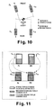
- Figure 10 is a simplified schematic diagram of the vehicle of Figure 9 turning to the left to show the changes in the moment arm lengths and the changes in reassignment of the braking torques in accordance with the first case;
- Figure 11 is a diagram illustrating the reassignment of the braking torques among the four wheel of the vehicle illustrated in Figures 9 and 10 in accordance with the first case;
- Figure 12 is a simplified schematic diagram of the vehicle equipped with the vehicle braking control apparatus in accordance with second and third cases of the present invention in which the vehicle is a front wheel drive with four wheels that have independent frictional braking on each wheel and independent regenerative braking on the rear wheels;
- Figure 13 is a simplified schematic diagram of the vehicle of Figure 12 turning to the left to show the changes in the moment arm lengths and the changes in reassignment of the braking torques in accordance with the second case;
- Figure 14 is a diagram illustrating the reassignment of the braking torques among the four wheel of the vehicle illustrated in Figures 12 and 13 in accordance with the second case;
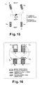
- Figure 15 is a simplified schematic diagram of the vehicle of Figure 12 turning to the left to show the changes in the moment arm lengths and the changes in reassignment of the braking torques in accordance with the third case;
- Figure 16 is a diagram illustrating the reassignment of the braking torques among the four wheel of the vehicle illustrated in Figures 12 and 15 in accordance with the third case;
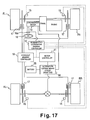
- FIG 17 is a simplified schematic diagram of the vehicle equipped with the vehicle braking control apparatus in accordance with a fourth case of the present invention in which the vehicle is a front wheel drive with four wheels that have independent frictional braking on each wheel and non-independent regenerative braking on the front wheels;
- Figure 18 is a simplified schematic diagram of the vehicle of Figure 17 turning to the left to show the changes in the moment arm lengths and the changes in reassignment of the braking torques in accordance with the fourth case;
- Figure 19 is a diagram illustrating the reassignment of the braking torques among the four wheel of the vehicle illustrated in Figures 17 and 18 in accordance with the fourth case;
- Figure 20 is a simplified schematic diagram of the vehicle equipped with the vehicle braking control apparatus in accordance with fifth and sixth cases of the present invention in which the vehicle is a front wheel drive with four wheels that have independent frictional braking on each wheel and independent regenerative braking on the front wheels;
- Figure 21 is a simplified schematic diagram of the vehicle of Figure 20 turning to the left to show the changes in the moment arm lengths and the changes in reassignment of the braking torques in accordance with the fifth case;
- Figure 22 is a diagram illustrating the reassignment of the braking torques among the four wheel of the vehicle illustrated in Figures 20 and 21 in accordance with the fifth case;
- Figure 23 is a simplified schematic diagram of the vehicle of Figure 20 turning to the left to show the changes in the moment arm lengths and the changes in reassignment of the braking torques in accordance with the sixth case;
- Figure 24 is a diagram illustrating the reassignment of the braking torques among the four wheel of the vehicle illustrated in Figures 20 and 23 in accordance with the sixth case.
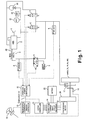
- FIG. 1 a simplified schematic block diagram of a vehicle is illustrated to explain preferred embodiments of the present invention.
- the vehicle is equipped with a vehicle braking control apparatus that is provided with a "regenerative cooperative braking control system" in accordance with the preferred embodiments of the present invention.
- the vehicle of Figure 1 is equipped with four wheels (i.e., a front left wheel FL, a front right wheel FR, a rear left wheel RL and a rear right wheel RR) that includes a drive train (not shown in Figure 1) to provided a driving force to one or more of the wheels FL, FR, RL and RR.
- the vehicle of Figure 1 that is equipped with the vehicle braking control apparatus includes either a front wheel drive train, or a rear wheel drive train or an all-wheel drive train.
- the vehicle braking control apparatus is configured and arranged to detect a steering degree of a pair of laterally spaced first wheels (e.g., the front wheels FL and FR) that are configured and arranged to be steered, and detect a total braking command value to be applied to the first steering wheels and a pair of laterally spaced second wheels (e.g., the rear wheels RL and RR) that are longitudinally separated from the first steering wheels in a front to aft vehicle direction.
- a steering degree of a pair of laterally spaced first wheels e.g., the front wheels FL and FR
- a pair of laterally spaced second wheels e.g., the rear wheels RL and RR
- the vehicle braking control apparatus is configured and arranged to vary a front and rear braking torque distribution between the first and second wheels while keeping a total required braking torque imparted to all of the wheels substantially constant, and adjust a left and right braking torque distribution of at least one of the pairs of the first and second wheels so that a left and right braking torque difference is applied to suppress a vehicle behavior that accompanies varying of the front and rear braking torque distribution based on the steering degree in the first wheels upon determining that steering in the first wheels is present.
- the distribution of braking torque to the left and right steering wheels produced by the steering is adjusted by creating a difference between the left and right braking torques, so that the difference between the left and right braking torques is increased in the direction in which vehicle behavior that accompanies the variation in distribution is suppressed as the steering amount increases.
- the adjustment can be carried out so that a difference is created between the left and right braking torques in the direction of suppressing vehicle behavior that accompanies the variation in distribution on the basis of the steering direction.
- adjustments are made to the braking torque distribution between the left and right steering wheels in accordance with the steering angle and other steering information when the braking torque distribution to the non-steering wheels is varied according to the relationship with other wheels.
- the vehicle braking control apparatus of the present invention basically includes a frictional braking system configured and arranged to impart independent frictional braking on each wheel of the wheels FL, FR, RL and RR, and a regenerative braking system configured and arranged to impart a regenerative braking torque on one or more of the wheels FL, FR, RL and RR.
- the vehicle of Figure 1 is equipped with either independent regenerative braking or non-independent regenerative braking that is applied to either the front wheels FL and FR or rear wheels RL and RR.
- the regenerative braking system is configured and arranged to effectively recover regenerative energy by controllably reducing the use of the frictional braking system and imparting a regenerative braking torque on one or more of the wheels FL, FR, RL and RR.
- the frictional (hydraulic) braking system is also configured in the same manner with three other wheels, and braking to each wheel can be independently controlled.
- the braking devices of the front wheels FL and FR are solely frictional braking devices, while the braking devices of the rear wheels RL and RR include both frictional braking devices and regenerative braking devices.
- the braking devices of the rear wheels RL and RR are solely frictional braking devices, while the braking devices of the front wheels FL and FR include both frictional braking devices and regenerative braking devices.
- the left and right front wheels FL and FR are steering wheels
- the left and right rear wheels RL and RR are non-steering wheels.
- the non-steering rear wheels are the other wheels, but the other wheels are not necessarily non-steering wheels.
- the frictional braking system is a relatively conventional frictional braking system that includes a brake pedal 1, a hydraulic booster 2, a master cylinder 3, a magnetic valve 4, a stroke simulator 5, a proportional pressurizing magnetic valve 6, a proportional depressurizing magnetic valve 7, an output sensor 8, an output sensor 9 and a hydraulic braking controller 10.
- the hydraulic braking controller 10 independently controls the hydraulic pressure in a conventional manner for imparting braking through frictional braking torque on the basis of hydraulic pressure on each of the wheels FL, FR, RL and RR.
- the regenerative braking system includes a motor controller 11, a regenerative cooperative braking controller 12, one or more alternating synchronous electric motors 13 and an electric current control circuit 14 (inverter) for AC/DC conversion.
- the one or more electric motors 13 are operatively coupled to one or more of wheels FL, FR, RL and RR so that either a pair of front wheels or a pair of rear wheels are driven/braked by the one or more electric motors 13.
- the regenerative braking system based on the electric motor(s) 13 is either independently or non-independently provided to a pair of left and right wheels.
- the motor controller 11 controls regenerative braking torque on the basis of the regenerative braking torque command value from the regenerative cooperative braking controller 12.
- the regenerative braking system is configured and arranged such that a regenerative braking torque is applied on one or more of the wheels FL, FR, RL and RR.
- the regenerative braking torque is in the form of an electrical load that is produced by the alternating synchronous electric motor 13, as shown in Figure 1.
- the brake pedal 1 is operated to create the braking torque stipulated by the driver, and the brake pedal 1 is linked to the master cylinder 3 by way of the hydraulic booster 2.
- the hydraulic booster 2 boosts and feeds braking pressure (downward force of the pedal) to the master cylinder 3 in accordance with the amount of downward force applied to the brake pedal 1, using high braking hydraulic pressure created by a pump 20 and stored in an accumulator 21.
- the high braking hydraulic pressure is also used as the base pressure for hydraulic pressure feedback control.
- the pump 20 is sequentially controlled by a pressure switch 22.
- a hydraulic fluid reservoir 23 is provided for supplying hydraulic fluid to the hydraulic braking devices.
- the master cylinder 3 is connected to the wheel cylinder 17 of each wheel by way of the magnetic valve 4 for switching fluid channels.
- Figure 1 shows a state in which the magnetic valve 4 for switching fluid channels is not energized, and illustrates a state in which the fluid of the master cylinder 3 is fed directly to the wheel cylinder 17.
- the master cylinder 3 becomes connected to the stroke simulator 5 (the same hydraulic load as the wheel cylinder 17) and is disconnected from the wheel cylinders 17.
- the proportional pressurizing magnetic valve 6 for controlling the hydraulic pressure is energized, the output pressure of the pump 20 or the stored pressure in the accumulator 21 is fed to each wheel cylinder 17 to increase the pressure.
- the proportional depressurizing magnetic valve 7 for controlling the hydraulic pressure is energized, the braking hydraulic pressure of each wheel cylinder 17 is restored to that of the reservoir 23 to reduce the pressure.
- the braking hydraulic pressure of the wheel cylinders 17 can thereby be individually controlled.
- the output pressure of the master cylinder 3 (required amount of braking by the driver) is detected by the output sensor 8, and the detection signal is fed to the hydraulic braking controller 10.
- the braking hydraulic pressure of each wheel cylinder 17 in a state disconnected from the master cylinder 3 is detected by the output sensor 9, and this detection signal is also fed to the hydraulic pressure braking controller 10.
- the hydraulic pressure braking controller 10 controls the pressurizing magnetic valve 6 and the depressurizing magnetic valve 7 on the basis of the detection signals from the output sensors 8 and 9.
- the braking hydraulic pressure is individually controlled for each wheel cylinder 17. The braking torque produced is thereby imparted to the wheels by a frictional load with the desired magnitude.
- the alternating synchronous motor(s) 13 is linked to one or both of the drive wheels by way of a deceleration mechanism 24.
- the electric motor 13 operates as a drive motor for transmitting drive torque to the drive wheels.
- the electric motor 13 also operates as an electric generator by the road surface drive torque from the drive wheels, and store vehicle kinetic energy produced by regenerative braking control as electricity in a battery 25 by way of the electric current control circuit 14 (inverter) for AC/DC conversion.
- the electric current control circuit 14 inverter
- the inverter 14 converts the electric current between alternating current and direct current on the basis of a three-phase PWM signal from the motor controller 11. In other words, the electric motor 13 is controlled based on commands from the motor controller 11.
- the motor controller 11 controls regenerative braking torque on the basis of the regenerative braking torque command value from the regenerative cooperative braking controller 12. Also, the drive torque produced by the electric motor 13 is controlled during driving. The motor controller 11 calculates the maximum allowable regenerative torque value that is determined based on the charged state of the battery 25, the temperature, and other factors, and the calculation result is fed to the regenerative cooperative braking controller 12.
- a wheel velocity sensor 15 is provided for measuring the wheel velocity. Magnetic pickup or another method may be used, for example.
- the steering angle sensor 16 is provided in which an encoder or the like is used.
- the hydraulic braking controller 10, the motor controller 11, and the regenerative cooperative braking controller 12 constitute an excess distribution component that is configured and arranged to reassign regenerative braking torque command values and hydraulic pressure braking torque command values to the appropriate wheel.
- the hydraulic braking controller 10, the motor controller 11, and the regenerative cooperative braking controller 12 are composed of, for example, one-chip microcomputer (or a plurality of chips that realize the same functions) having various timer functions, a CPU, ROM, RAM, digital ports, and A/D ports, as well as a high-speed communication circuit and other components.
- Figure 2 shows a functional block diagram related to the present invention.
- the independent braking device is configured with the hydraulic braking controller 10 and the motor controller 11, and the other functions are implemented with a regenerative cooperative braking controller 12.
- acceleration and torque are such that deceleration and torque in the braking direction are defined as negative values.
- the routine for the regenerative cooperative braking controller 12 is carried out at a predetermined sampling cycle (10 msec, for example).
- step S10 the output pressure P mc of the master cylinder 3 (total required braking amount requested by the driver) and the braking hydraulic pressure P wc of each wheel cylinder 17 are computed based on the detection signals from the output sensors 8 and 9, and the system then advances to step S20.
- step S20 the velocity of each wheel is measured based on signals from the wheel velocity sensors by using a timer with an input capture function in the microcomputer, and the term V w is taken to be the maximum value thereof.
- Bandpass filtering indicated by the transmission variable Fbpf (s) in the Equation (1) below is furthermore carried out, the estimated value ⁇ v of deceleration of the drive wheels is calculated, and the system advances to step S30.
- Equation (1) the term "s" is a Laplace operator, the term ⁇ is the intrinsic angle frequency, and the term ⁇ is an attenuation coefficient.
- step S30 the maximum allowable regenerative torque T mmax that can be currently used is read from the high-speed communication receiving buffer connected to the motor controller 11, and the system advances to step S40.
- the motor controller 11 determines the maximum allowable regenerative torque T mmax in accordance with the charge ratio of the battery, and other factors.
- step S40 the target deceleration ⁇ dem is calculated using the master cylinder pressure P mc and a vehicle specification constant K1 stored in the ROM in advance, and the system advances to step S50.
- ⁇ dem - (P mc ⁇ constant K1)
- the settings are also varied in accordance with physical amounts based on the automatic braking of inter-vehicle distance control, velocity control, and other types of control in a vehicle with these types of control.
- step S50 the braking torque command value T d_FF (feed forward term) required to realize the target deceleration ⁇ dem is calculated, and the system advances to step S60. More specifically, the target deceleration ⁇ dem is first transformed into braking torque by using a vehicle specification constant K2. Furthermore, the braking torque command value T d_FF (feed forward term) is calculated by performing the C FF (s) expressed below by Equation (3) for a feed forward compensator (phase compensator) in order to cause the response characteristics P m (s) of the controlled vehicle to match the reference model characteristics F ref (s). In actual practice, digitization and calculation are performed in the same manner as described above.
- step S60 the master cylinder pressure P mc and a predetermined value (value approximate to zero) are compared. If the master cylinder pressure P mc is greater (brake operation by the driver), the system advances to step S70, and if smaller (no brake operation), the system advances to step S90.
- a braking torque command value T d_FB (feedback term) required to realize the target deceleration ⁇ dem is calculated in the subsequently described routine, and the system advances to step S80.
- the deceleration controller of the present embodiment is configured with "two degrees of freedom," as shown in Figure 4.
- the deceleration controller is composed of a feed forward compensator (block A), a reference model (block B), and a feedback compensator (block C).
- the stability, resistance to external disturbance, and other closed loop capabilities are adjusted with the feedback compensator, and responsiveness to the target acceleration is adjusted in principle (when there is no modeling error) with the feed forward compensator.
- the feedback bias ⁇ is processed by the feedback compensator C FB (s) to calculate the braking command value T d_FB (feedback term).
- the feedback compensator C FB (s) performs this operation with a basic PI controller, as demonstrated by Equation (6) below.
- the control constants Kp and Ki in the following Equation are set with consideration given to the gain margins or phase margins.
- C FB (S) (Kp ⁇ s + Ki) s
- step S80 the braking command value T d_com is calculated by using an adder to add the F/F and F/B terms of the calculated braking torque command values, and the system advances to step S100.
- Equations (4) and (6) carry out calculations with the recurrence Equation obtained through digitizing in the same manner as described above.
- step S90 the braking torque command value T d_FB (feedback term) and the internal variables used in the computation of the feedback compensator (digital filter) are initialized (the integral term of the PI compensator is initialized).
- step S 100 the braking torque command value T d_com is distributed in an ideal fashion to the front and rear wheels, and the system advances to step S 110.
- an ideal distribution line such as one in which the front and rear wheels are simultaneously locked, a distribution line in which the front wheels are slightly biased to avoid locking the rear wheels first, or other basic front and rear distribution characteristics such as those shown in Figure 5 are stored in a table in advance with consideration for the movement of the front and rear load during deceleration, and the braking torque command value T d_com is distributed to the front wheel braking torque command values T d_FR and T d_FL , and to the rear wheel braking torque command values T d_RR and T d_RL by looking up these values in the table.
- T d_FR 0.5 ⁇ table lookup for front wheels (input: T d_com )
- T d_FL 0.5 ⁇ table lookup for front wheels (input: T d_com )
- T d_RR 0.5 ⁇ table lookup for rear wheels (input: T d_com )
- T d_RL 0.5 ⁇ table lookup for rear wheels (input: T d_com )
- step S 110 the results are assigned as much as possible to the regenerative braking torque command value of the rear wheels, and the remainder is assigned to the hydraulic pressure braking torque command value with the aim of improving fuel economy within the range of braking torque command values for each wheel in accordance with the ideal front and rear braking torque distribution calculated in step S100, and the system advances to step S120.
- the basic distribution to the four wheels remains unchanged. It should be noted that the present embodiment is an example of a regenerative braking device that is applied solely to the rear wheels, and the braking torques are all negative values.
- step S 110 the braking torque command values for the left and right rear wheels that have been set in step S100 are assigned to the regenerative braking torque command value and the hydraulic pressure torque command value, respectively, and the system advances to step S120.
- the routine is carried out so as to assign as much of the command value as possible to the regenerative braking torque command value.
- the amount assigned to the regenerative braking torque command value is calculated first on the basis of the Equations below. If the braking torque command value is absolutely greater than the maximum allowable regenerative torque that can be used by assignment on the basis the Equations below, the regenerative braking torque command value is assigned to a command value equivalent to the maximum allowable regenerative torque. Were this not the case, the regenerative braking torque command value would be the same value as the braking torque command value, and the hydraulic pressure braking torque command value would be zero.
- T m0_RR max (T d_RR , T mmax_RR )
- T m0_RL max (T d_RL , T mmax_RL )
- T mmax_RL and T mmax_RR are the maximum allowable regenerative torques in the left and right rear wheels, respectively.
- the hydraulic pressure braking torque command value assigned to each wheel is calculated based on the Equations below.
- the braking torque command value is taken to be the hydraulic braking torque command value in unaltered form, but on the rear wheel side, only an amount equivalent to the portion not assigned to the regenerative braking torque command value taken to be the hydraulic pressure braking torque command value.
- T b0_FR T d_FR
- T b0_FL T d_FL
- step S120 an excess distribution computation unit that constitutes an excess distribution computation device is started, correction based on the steering angle information is carried out, and the system then advances to step S 130.
- step S 130 the hydraulic pressure command value of the each of the front and rear wheels is calculated as shown by the following Equations by using a vehicle specification constant K3 stored in ROM in advance on the basis of the hydraulic pressure braking torque command for each wheel, and the system advances to step S 140.
- P b_FR - (T b_FR ⁇ constant K3)
- P b_FL - (T b_FL ⁇ constant K3)
- P b_RR - (T b_RR ⁇ constant K3)
- P b_RL - (T b_RL ⁇ constant K3)
- step S 140 the hydraulic pressure command value and the regenerative braking torque command value for each wheel are fed to the hydraulic pressure braking controller 10 and the motor controller 11, respectively, and the routine is completed.
- step S300 The recoverable surplus amount of the regenerative braking torque in the rear wheels is first calculated in step S300 on the basis of the Equations shown below, and the system advances to step S310.
- T mmargin_RR T mmax_RR - T m0_RR
- T mmargin_RL T mmax_RL - T m0_RL
- step S310 the braking torque ⁇ T that can be reassigned between the front and rear wheels is calculated based on the following Equation, and the system advances to step S320. All the braking torques are negative values.
- ⁇ T max ⁇ (T mmargin_RR + T mmargin_RL ), (T b0_FR + T b0_FL) ⁇
- the lesser of the two values selected from the absolute value of the excess amount of the total regenerative braking torque and the absolute value of the total braking torque command value on the front wheel side is taken to be the re-assignable braking torque ⁇ T between the front and rear wheels. If the absolute value of the total braking torque command value is less on the front wheel side, as described below, the total braking torque command value portion on the front wheel side will thereby be reassigned to the regenerative braking of the rear wheel side. Conversely, if the absolute value of total braking torque command value on the front wheel side is greater, an amount equal to the surplus amount of total regenerative braking torque will be reassigned to regenerative braking.
- step S320 the steering angle ⁇ , which constitutes steering information, is calculated from a detection value obtained by measuring the rotation angle and direction on the basis of the edge or level of the output pulse of the encoder or another steering angle sensor in another routine with a shorter computational cycle, and the system advances to step S330.
- step S330 the actual steering angle ⁇ of the front wheels is calculated from the steering angle ⁇ by using the gear ratio of the steering mechanism. Furthermore, in step S340, the direct distances L FL , L FR , L RL , L RR (moment arm lengths) from the center of gravity of the vehicle to the vectors in the direction of rotation of each wheel are calculated based on the Equations below, and the system advances to step S350.
- the distances L A , L B , L F , and L R used in the following Equations are defined as shown in Figure 7.
- L FR (L A + L B )cos ⁇ - L FL
- step S350 the reassigned braking torque amounts F FR , F FL , F RR , and F RL for each wheel that satisfy Equations (14) and (15) below are calculated
- F RL F RR
- the Equations can easily be solved because they are simultaneous linear Equation for F FR and F FL .
- the regenerative braking devices of the rear wheels RL and RR are not necessarily left and right independent.
- step S360 the final regenerative braking torque command value and hydraulic braking torque command value for each wheel are calculated based on the Equations below, and the system then returns to the beginning.
- T m_RR T m0_RR + F RR ⁇ R
- T m_RL T m0_RL + F RL ⁇ R
- T b_FR Tb 0_FR - F FR ⁇ R
- T b_FL T b0_FL - F FL ⁇ R
- step S320 constitutes a steering detection component or device
- steps S330 to S360 constitute left and right distribution adjustment component or device.
- surplus regenerative braking torque when surplus regenerative braking torque is available, priority can be placed on fuel economy, and all or part of the braking torque command value on the front wheel side can be assigned to regenerative braking on the rear wheel side.
- braking on the rear wheel side is carried out solely with regenerative braking, and the hydraulic braking torque command value on the rear wheel side is zero.
- the maximum regenerative braking torque gradually increases while the required total braking torque remains constant, the ideal distribution to the front and rear wheels is preserved until the frictional braking torque of the rear wheels is entirely replaced with regenerative braking torque.
- the frictional braking torque on the front wheel side replaces the regenerative braking torque of the rear wheels, and the system changes to a state in which the ideal distribution to the front and rear wheels becomes unbalanced.
- the maximum regenerative braking torque varies depending on the charge ratio of the battery 25 that takes in regenerative electric power, the rotational speed of the electric motor 13 (proportional to the vehicle velocity), and other factors.
- braking power is simply reassigned between the front and rear wheels without regard to whether the total braking torque has an ideal front and rear braking torque distribution.
- the frictional braking torque of the front wheels is reassigned to the regenerative braking torque of the rear wheels, and the amount reassigned to the left and right wheels of the front and the rear wheels is simply set to the same amount, then the front and rear distribution will merely be unbalanced if the vehicle is traveling in a straight line, but a new yaw moment not intended by the driver will be created as a result of placing priority on improving the fuel economy when the vehicle is turning.
- the excess distribution component is configured the reassigned amounts (F FR , F FL , F RR , F RL ) of braking torque for each wheel are calculated by initially determining an amount ⁇ T reassigned to the front and rear wheels, with priority being given to maximizing the regenerative amount.
- the excess distribution component is configured such that the reassigned amounts (F FR , F FL , F RR , F RL ) of braking torque for each wheel are calculated to give priority to the prevention of the generation of a new yaw moment.
- step S500 the steering angle ⁇ , which constitutes steering information, is calculated from the detection value obtained by measuring the rotation angle and direction on the basis of the edge or level of the output pulse of the encoder or another steering angle sensor in another routine with a shorter computational cycle, and the system advances to step S510.
- step S510 the actual steering angle ⁇ of the front wheels is calculated from the steering angle ⁇ by using the gear ratio of the steering mechanism. Furthermore, in step S520, the direct distances L FL , L FR , L RL , L RR (moment arm lengths) from the center of gravity of the vehicle to the vectors in the direction of rotation of each wheel are calculated based on the Equations (13.1) to (13.4), as set forth above, and the system advances to step S530.
- step S530 a solution is calculated that satisfies the conditions (A) and (B) of the Equations (14) and (15), as set forth above, and the conditions of Equations (18.1) to (18.4) below and produces the maximum reassigned amount (F FR + F FL ) for the front and rear wheels, and the system advances to step S540.
- the term R is the effective tire radius.
- step S540 corrections are made and the final regenerative braking torque command value and hydraulic braking torque command value for each wheel are calculated on the basis of the reassigned amounts (see, Equations (16.1), (16.2), (17.1) and (17.2) above). The routine is ended and the system returns to the beginning.
- An effect of the present embodiment is that steering stability can be securely maintained because priority is given to avoiding the occurrence of a yaw moment and because the amounts reassigned to the front and rear wheels are limited while consideration is given to the braking torque (lock limit) that can be transmitted to the road surface.
- Other operation and effects are the same as in the first embodiment.
- the reassigned amounts (F FR , F FL , F RR , F RL ) for each wheel are different depending on the vehicle configuration (whether the regenerative braking device is left and right independent, for example) and the restraint conditions (maximum regenerative capacity, lock limit, and other conditions). All the cases are summarized below, including cases in which the front wheels have one or more regenerative braking devices.
- a left and right braking torque distribution is assigned to the front wheels FL and FR to reduce partially or completely a new reassignment-induced yaw moment that is caused by the command values reassigning the front and rear braking torque distribution.
- the vehicle in this case is configured as a front wheel drive vehicle with each of the four wheels having independent frictional braking and the rear wheels RL and RR also having left and right non-independent regenerative braking.
- Figure 10 is a simplified schematic diagram of the vehicle of Figure 9 turning to the left to show the changes in the moment arm lengths and the changes in reassignment of the braking torques in accordance with the first case
- Figure 11 is a diagram illustrating the reassignment of the braking torques among the four wheel of the vehicle illustrated in Figures 9 and 10 in accordance with the first case.
- the front and rear braking torque distribution is varied to increase the braking torques of the rear wheels RL and RR evenly and decrease the braking torques of the front wheels FL and FR unevenly.
- the left and right braking torque distribution of the frictional braking devices is varied in the front wheels FL and FR, while the left and right braking torque distribution of the rear wheels RL and RR remain equal using non-independent regenerative braking.
- FIG. 10 and 11 an example of reassigning braking torque between the front and rear wheels by the above-described control is illustrated in which a left and right braking torque difference is assigned to the front wheels FL and FR and the regenerative braking torques of the rear wheels RL and RR is maximized.
- a left and right braking torque difference is assigned to the front wheels FL and FR and the regenerative braking torques of the rear wheels RL and RR is maximized.
- the moment arm on the left front wheel side is made shorter and the moment arm on the right front wheel side is made longer.
- the reassigned braking torque amounts F FR , F FL , F RR , and F RL for each wheel that satisfy the above Equations (14) and (15) are calculated as in step S350 or step S530. If absolutely preventing the generation of new yaw moment is given priority, then various restraint conditions are set for limiting the amount of braking torque reassigned to the wheels as indicated in the above Equations (18.1) to (18.4). Thus, the process of calculating the reassigned amounts of braking torque for each wheel is set so as to maximize the amount reassigned from the front wheels FL and FR to the rear wheels RL and RR.
- the regenerative braking torque control devices are not left and right independent, so the maximum regenerative braking amount and the left and right values of the basic distribution regenerative braking torque command values are equal.
- T mmax_RR T mmax_RL
- T m0_RR T m0_RL
- ⁇ T max( ⁇ T lim_1, ⁇ T lim_2, ⁇ Tl im_3, ⁇ T lim_4 )
- a left and right braking torque distribution is assigned to the rear wheels RL and RR to reduce partially or completely a new reassignment-induced yaw moment that is caused by the command values reassigning the front and rear braking torque distribution.
- the vehicle in this case is configured as a front wheel drive vehicle with each of the four wheels having independent frictional braking and the rear wheels RL and RR also having left and right independent regenerative braking.
- Figure 13 is a simplified schematic diagram of the vehicle of Figure 12 turning to the left to show the changes in the moment arm lengths and the changes in reassignment of the braking torques in accordance with the second case
- Figure 14 is a diagram illustrating the reassignment of the braking torques among the four wheel of the vehicle illustrated in Figures 12 and 13 in accordance with the second case.
- the front and rear braking torque distribution is varied to unequally increase the braking torques of the rear wheels RL and RR and equally decrease the braking torques of the front wheels FL and FR.
- the left and right braking torque distribution of the rear wheels RL and RR is varied in the rear wheels RL and RR, while the left and right braking torque distribution of the frictional braking devices of the front wheels FL and FR remain equal.
- FIG. 13 and 14 an example of reassigning braking torque between the front and rear wheels by the above-described control is illustrated in which a left and right braking torque difference is assigned to the rear wheels RL and RR and the regenerative braking torques of the rear wheels RL and RR is maximized.
- the left and right braking torque difference of the rear wheels RL and RR can be produced by either solely using the rear wheel frictional braking devices (case 2a), solely using the rear wheel regenerative braking devices (case 2b) or a combination of both the rear wheel frictional braking devices and the rear wheel regenerative braking devices (case 2c).
- the reassigned braking torque amounts F FR , F FL , F RR , and F RL for each wheel that satisfy the above Equations (14) and (15) are calculated as in step S350 or step S530. If absolutely preventing the generation of new yaw moment is given priority, then various restraint conditions are set for limiting the amount of braking torque reassigned to the wheels as indicated in the above Equations (18.1) to (18.4). Thus, the process of calculating the reassigned amounts of braking torque for each wheel is set so as to maximize the amount reassigned from the front wheels FL and FR to the rear wheels RL and RR.
- Equation (30) the amount ⁇ T of the braking torque reassigned to the front and rear wheels is calculated with the following Equation (30), which is derived from Equation (14).
- Equation (31.1) and (31.2) are used to calculate the reassigned amounts of braking torque of the rear wheels RL and RR in this case.
- F RL ⁇ T ⁇ (2L RR +L FL - L FR ) 2R ⁇ (L RL + L RR )
- F RR ⁇ T ⁇ (2L RL - L FL + L FR ) 2R ⁇ (L RL + L RR )
- the restraint conditions for the amount of braking torque reassigned to the rear wheels are different for the situation (case 2a) in which a left and right braking torque difference is assigned solely with frictional braking, the situation (case 2b) in which the left and right braking torque difference is assigned solely with regenerative braking, and the situation (case 2c) in which the left and right braking torque difference is assigned with both frictional braking and regenerative braking. Therefore, the method for calculating the reassigned amount whereby yaw moment is not generated in each of the cases is described. [00142] First, the situation (case 2a) will be discussed in which the left and right braking torque difference is assigned solely with the frictional braking of the rear wheels.
- the wheels on the outside of the turn experience a larger braking torque than the wheels on the inside of the turn as an absolute value.
- the limit of the wheels on the outside of the turn is such that the sum of the braking torques produced by the left and right independent regenerative braking torque and the frictional braking torque does not exceed the lock limit value. Frictional braking is also added, so the limit at this time may exceed the maximum regenerative braking amount.
- the wheels on the inside of the turn are not required to exceed the maximum regenerative braking amount, and the limit does not exceed the maximum regenerative braking amount and the lock limit value.
- the maximum value ⁇ T of the amount reassigned thereby is calculated with the following Equations.
- ⁇ T max ( ⁇ T lim , ⁇ T lim_tmmax2 ⁇ T lim_flim1 , ⁇ T lim_flim2 )
- ⁇ T lim_tmmax1, ⁇ T lim_flim1, ⁇ T lim_flim2 max ( ⁇ T lim , ⁇ T lim_tmmax1, ⁇ T lim_flim1, ⁇ T lim_flim2 )
- the amount of braking reassigned to each wheel is calculated with the maximum ⁇ T of the reassigned amount using Equations (30), (31.1) and (31.2) and (15) that were previously mentioned.
- a left and right braking torque distribution is assigned to both the front and rear wheels FL, FR, RL and RR to reduce partially or completely a new reassignment-induced yaw moment that is caused by the command values reassigning the front and rear braking torque distribution.
- the vehicle in this case is configured as a front wheel drive vehicle with each of the four wheels having independent frictional braking and the rear wheels RL and RR also having left and right independent regenerative braking as seen in Figure 12.
- Figure 15 is a simplified schematic diagram of the vehicle of Figure 12 turning to the left to show the changes in the moment arm lengths and the changes in reassignment of the braking torques in accordance with the third case
- Figure 16 is a diagram illustrating the reassignment of the braking torques among the four wheel of the vehicle illustrated in Figure 12 in accordance with the third case.
- the front and rear braking torque distribution is varied to unequally increase the braking torques of the rear wheels RL and RR and unequally decrease the braking torques of the front wheels FL and FR.
- the left and right braking torque distributions of both the front and rear wheels FL, FR, RL and RR are varied in both the front and rear wheels FL, FR, RL and RR.
- FIG. 15 and 16 an example of reassigning braking torque between the front and rear wheels by the above-described control is illustrated in which a left and right braking torque difference is assigned to both the front and rear wheels FL, FR, RL and RR and the regenerative braking torques of the rear wheels RL and RR is maximized.
- the left and right braking torque difference of the rear wheels RL and RR can be produced by either solely using the rear wheel frictional braking devices (case 3a), solely using the rear wheel regenerative braking devices (case 3b) or a combination of both the rear wheel frictional braking devices and the rear wheel regenerative braking devices (case 3c).
- the reassigned braking torque amounts F FR , F FL , F RR , and F RL for each wheel that satisfy the above Equations (14) and (15) are calculated as in step S350 or step S530. If absolutely preventing the generation of new yaw moment is given priority, then various restraint conditions are set for limiting the amount of braking torque reassigned to the wheels as indicated in the above Equations (18.1) to (18.4). Thus, the process of calculating the reassigned amounts of braking torque for each wheel is set so as to maximize the amount reassigned from the front wheels FL and FR to the rear wheels RL and RR.
- ⁇ can be a fixed value that is set in accordance with vehicle characteristics, or can be allowed to vary in accordance with steering and other behaviors of the vehicle.
- the amount ⁇ T reassigned to the front and rear wheels is not set if absolutely preventing the generation of new yaw moment is given priority over maximizing regenerative amount. Rather, the amount ⁇ T reassigned from the front wheels to the rear wheels to maximizes the regenerated amount is calculated with the following method using the conditional expressions set forth in the above Equations (18.1) to (18.4).
- the restraint conditions for the amount of braking torque reassigned to the rear wheels are different for the situation (case 3a) in which a left and right braking torque difference is assigned solely with frictional braking, the situation (case 3b) in which the left and right braking torque difference is assigned solely with regenerative braking, and the situation (case 3c) in which the left and right braking torque difference is assigned with both frictional braking and regenerative braking.
- the method for calculating the reassigned amount whereby yaw moment is not generated for each of the cases 3a to 3c is the same as the methods for calculating the reassigned amount used in cases 2a to 2c. Since these methods for calculating the reassigned amount are discussed above, they will not be repeated.
- T m_RR max(T d0_RR + F RR ⁇ R, T mmax_RR )
- T m _ RL max(T d0_RL + F RL ⁇ R, T mmax_RL )
- the fourth to sixth cases illustrate vehicle configurations in which the front wheels FL and FR have one or more regenerative braking devices.
- the front and rear braking torque distribution is varied to increase the braking torques of the front wheels FL and FR and decrease the braking torques of the rear wheels RL and RR.
- the left and right braking torque distribution is varied differently depending on the vehicle configuration.
- the fourth to sixth cases will not be discussed in as much detail.
- a left and right braking torque distribution is assigned to the rear wheels RL and RR to reduce partially or completely a new reassignment-induced yaw moment that is caused by the command values reassigning the front and rear braking torque distribution.
- the vehicle in this case is configured as a front wheel drive vehicle with each of the four wheels having independent frictional braking and the front wheels FL and FR also having left and right non-independent regenerative braking.
- Figure 18 is a simplified schematic diagram of the vehicle of Figure 17 turning to the left to show the changes in the moment arm lengths and the changes in reassignment of the braking torques in accordance with the fourth case
- Figure 19 is a diagram illustrating the reassignment of the braking torques among the four wheel of the vehicle illustrated in Figures 17 and 18 in accordance with the fourth case.
- the front and rear braking torque distribution is varied to increase the braking torques of the front wheels FL and FR evenly and decrease the braking torques of the rear wheels RL and RR unevenly.
- the left and right braking torque distribution of the frictional braking devices is varied in the rear wheels RL and RR, while the left and right braking torque distribution of the front wheels FL and FR remain equal using non-independent regenerative braking.
- FIG. 18 and 19 an example of reassigning braking torque between the front and rear wheels by the above-described control is illustrated in which a left and right braking torque difference is assigned to the rear wheels RL and RR and the regenerative braking torques of the front wheels FL and FR is maximized.
- a left and right braking torque difference is assigned to the rear wheels RL and RR and the regenerative braking torques of the front wheels FL and FR is maximized.
- the moment arm on the left front wheel side is made shorter and the moment arm on the right front wheel side is made longer.
- a left and right braking torque distribution is assigned to the front wheels FL and FR to reduce partially or completely a new reassignment-induced yaw moment that is caused by the command values reassigning the front and rear braking torque distribution.
- the vehicle in this case is configured as a front wheel drive vehicle with each of the four wheels having independent frictional braking and the front wheels FL and FR also having left and right independent regenerative braking.
- Figure 21 is a simplified schematic diagram of the vehicle of Figure 20 turning to the left to show the changes in the moment arm lengths and the changes in reassignment of the braking torques in accordance with the fifth case
- Figure 22 is a diagram illustrating the reassignment of the braking torques among the four wheel of the vehicle illustrated in Figures 20 and 21 in accordance with the fifth case.
- the front and rear braking torque distribution is varied to unequally increase the braking torques of the front wheels FL and FR and equally decrease the braking torques of the rear wheels RL and RR.
- the left and right braking torque distribution of the front wheels FL and FR is varied in the front wheels FL and FR, while the left and right braking torque distribution of the frictional braking devices of the rear wheels RL and RR remain equal.
- FIG. 21 and 22 an example of reassigning braking torque between the front and rear wheels by the above-described control is illustrated in which a left and right braking torque difference is assigned to the front wheels FL and FR and the regenerative braking torques of the front wheels FL and FR is maximized.
- the left and right braking torque difference of the front wheels FL and FR can be produced by either solely using the front wheel frictional braking devices (case 5a), solely using the front wheel regenerative braking devices (case 5b) or a combination of both the front wheel frictional braking devices and the front wheel regenerative braking devices (case 5c).
- the vehicle in this case is configured as a front wheel drive vehicle with each of the four wheels having independent frictional braking and the front wheels FL and FR also having left and right independent regenerative braking as seen in Figure 20.
- Figure 23 is a simplified schematic diagram of the vehicle of Figure 20 turning to the left to show the changes in the moment arm lengths and the changes in reassignment of the braking torques in accordance with the sixth case, while Figure 24 is a diagram illustrating the reassignment of the braking torques among the four wheel of the vehicle illustrated in Figures 20 and 23 in accordance with the sixth case.
- the front and rear braking torque distribution is varied to unequally decrease the braking torques of the rear wheels RL and RR and unequally increase the braking torques of the front wheels FL and FR.
- the left and right braking torque distributions of both the front and rear wheels FL, FR, RL and RR are varied in both the front and rear wheels FL, FR, RL and RR.
- FIG. 23 and 24 an example of reassigning braking torque between the front and rear wheels by the above-described control is illustrated in which a left and right braking torque difference is assigned to both the front and rear wheels FL, FR, RL and RR and the regenerative braking torques of the front wheels FL and FR is maximized.
- the left and right braking torque difference of the front wheels FL and FR can be produced by either solely using the front wheel frictional braking devices (case 6a), solely using the front wheel regenerative braking devices (case 6b) or a combination of both the front wheel frictional braking devices and the front wheel regenerative braking devices (case 6c).
- the front wheels are exemplified as the steering wheels, but the rear wheels can be steering wheels as well.
- the vehicle can be one in which regenerative braking is carried out on the steering wheel side.
- each of the six cases, discussed above can be applied to rear wheel drive vehicles in which the internal combustion engine drives the rear wheels.
- control is performed such that a difference is imparted to the distribution of braking torques to the left and right steering wheels by an amount that corresponds to the steering amount when braking torque is reassigned to the front and rear, but the present invention is not limited to this option alone.
- adjustment may be carried out so that a constant braking torque difference is imparted to the distributions in the left and right steering wheels.
- the following directional terms "forward, rearward, above, downward, vertical, horizontal, below and transverse” as well as any other similar directional terms refer to those directions of a vehicle equipped with the present invention. Accordingly, these terms, as utilized to describe the present invention should be interpreted relative to a vehicle equipped with the present invention.
- the term “detect” as used herein to describe an operation or function carried out by a component, a section, a device or the like includes a component, a section, a device or the like that does not require physical detection, but rather includes determining or computing or the like to carry out the operation or function.
- the term “configured” as used herein to describe a component, section or part of a device includes hardware and/or software that is constructed and/or programmed to carry out the desired function.
Applications Claiming Priority (2)
| Application Number | Priority Date | Filing Date | Title |
|---|---|---|---|
| JP2004008243 | 2004-01-15 | ||
| JP2004008243 | 2004-01-15 |
Publications (3)
| Publication Number | Publication Date |
|---|---|
| EP1555184A2 true EP1555184A2 (fr) | 2005-07-20 |
| EP1555184A3 EP1555184A3 (fr) | 2006-04-26 |
| EP1555184B1 EP1555184B1 (fr) | 2010-05-26 |
Family
ID=34616890
Family Applications (1)
| Application Number | Title | Priority Date | Filing Date |
|---|---|---|---|
| EP05250093A Expired - Fee Related EP1555184B1 (fr) | 2004-01-15 | 2005-01-11 | dispositif de contrôle de freinage pour véhicules |
Country Status (4)
| Country | Link |
|---|---|
| US (1) | US7409280B2 (fr) |
| EP (1) | EP1555184B1 (fr) |
| CN (1) | CN100469631C (fr) |
| DE (1) | DE602005021412D1 (fr) |
Cited By (18)
| Publication number | Priority date | Publication date | Assignee | Title |
|---|---|---|---|---|
| WO2009077835A1 (fr) * | 2007-12-14 | 2009-06-25 | Toyota Jidosha Kabushiki Kaisha | Dispositif de commande de comportement de véhicule, et procédé de commande de comportement de véhicule |
| WO2009132720A1 (fr) * | 2008-04-29 | 2009-11-05 | Robert Bosch Gmbh | Procédé de commande d'un système de pompage double action dans des propulsions hybrides |
| EP2172378A1 (fr) * | 2008-10-06 | 2010-04-07 | Ford Global Technologies, LLC | Procédé et dispositif pour le freinage par récupération d'un véhicule |
| EP2239179A1 (fr) * | 2009-04-07 | 2010-10-13 | Honda Motor Co., Ltd. | Système de direction d'un véhicule |
| FR2970682A1 (fr) * | 2011-01-25 | 2012-07-27 | Renault Sas | Procede de pilotage d'un moyen de recuperation de l'energie generee au freinage d'un vehicule automobile |
| GB2502575A (en) * | 2012-05-31 | 2013-12-04 | Jaguar Cars | Braking control system having a first braking region without front axle friction braking and a second region that includes front axle friction braking |
| EP3100898A4 (fr) * | 2014-01-30 | 2017-03-01 | BYD Company Limited | Véhicule et procédé de commande de retour de freinage associé |
| US9849771B2 (en) | 2015-01-16 | 2017-12-26 | Byd Company Limited | Transmission unit, power transmission system and vehicle comprising the same |
| US9874266B2 (en) | 2014-09-10 | 2018-01-23 | Byd Company Limited | Power transmission system and vehicle comprising the same |
| EP2208629A4 (fr) * | 2007-11-09 | 2018-02-07 | Toyota Jidosha Kabushiki Kaisha | Dispositif de commande de force d'entraînement |
| US9889733B2 (en) | 2015-01-16 | 2018-02-13 | Byd Company Limited | Power transmission system and vehicle comprising the same |
| US9889734B2 (en) | 2015-01-16 | 2018-02-13 | Byd Company Limited | Power transmission system and vehicle comprising the same |
| US9919699B2 (en) | 2014-01-30 | 2018-03-20 | Byd Company Limited | Vehicle and method for controlling synchronizer of the same |
| US9944165B2 (en) | 2014-01-30 | 2018-04-17 | Byd Company Limited | Power transmission system for vehicle and vehicle comprising the same |
| WO2018206913A1 (fr) * | 2017-05-11 | 2018-11-15 | Arrival Limited | Procédé et appareil pour la commande d'un véhicule |
| US10166853B2 (en) | 2015-01-16 | 2019-01-01 | Byd Company Limited | Transmission unit, power transmission system and vehicle comprising the same |
| US10166973B2 (en) | 2014-10-20 | 2019-01-01 | Byd Company Limited | Vehicle and shifting control method and power transmission system thereof |
| US10670123B2 (en) | 2014-01-30 | 2020-06-02 | Byd Company Limited | Power transmission system for vehicle and vehicle comprising the same |
Families Citing this family (35)
| Publication number | Priority date | Publication date | Assignee | Title |
|---|---|---|---|---|
| DE10342937A1 (de) * | 2003-09-17 | 2005-04-14 | Robert Bosch Gmbh | Elektrohydraulische Bremsanlage |
| DE102006024239A1 (de) * | 2006-05-23 | 2007-11-29 | Siemens Ag | Verfahren zur Bremsung von elektrisch angetriebenen Fahrzeugen |
| US20080079311A1 (en) * | 2006-08-15 | 2008-04-03 | Ford Global Technologies, Llc | Vehicle regenerative braking system and method |
| JP4258548B2 (ja) * | 2006-12-19 | 2009-04-30 | トヨタ自動車株式会社 | 車両およびその制御方法 |
| JP4901503B2 (ja) * | 2007-01-24 | 2012-03-21 | 日立オートモティブシステムズ株式会社 | 制動制御装置 |
| JP4228085B2 (ja) * | 2007-02-07 | 2009-02-25 | トヨタ自動車株式会社 | 車両およびその制御方法、動力出力装置およびその制御方法、ならびに駆動装置およびその制御方法 |
| JP4636062B2 (ja) * | 2007-08-27 | 2011-02-23 | トヨタ自動車株式会社 | 車両の挙動制御装置 |
| US8315751B2 (en) * | 2008-02-29 | 2012-11-20 | GM Global Technology Operations LLC | Methods, program products, and systems for controlling braking in a hybrid vehicle |
| EP2349766B1 (fr) * | 2008-10-21 | 2012-12-12 | Renault Trucks | Procédé et système de détermination de la capacité d'un conducteur d'un véhicule hybride et véhicule équipé d'un tel système |
| JP5126371B2 (ja) | 2009-01-15 | 2013-01-23 | トヨタ自動車株式会社 | 車両安定化制御装置 |
| JP2011024353A (ja) * | 2009-07-16 | 2011-02-03 | Aisin Aw Co Ltd | 案内装置、案内方法、及び案内プログラム |
| DE112009005073B4 (de) * | 2009-07-17 | 2018-06-21 | Toyota Jidosha Kabushiki Kaisha | Fahrzeugverhaltenssteuervorrichtung |
| US8700241B2 (en) * | 2009-10-19 | 2014-04-15 | Toyota Jidosha Kabushiki Kaisha | Drive control device for standby four-wheel drive vehicle |
| DE102010008020A1 (de) * | 2010-02-08 | 2011-08-11 | Dr. Ing. h.c. F. Porsche Aktiengesellschaft, 70435 | Verfahren zum Betreiben eines Bremssystems eines hybriden Fahrzeugs, Bremssystem und Fahrzeug |
| BR112012021958A2 (pt) * | 2010-03-02 | 2016-06-07 | Int Truck Intellectual Prop Co | característica de reajuste do sistema de freio regenerativo e calibragem adaptativa para veículos elétricos e híbridos |
| JP5336445B2 (ja) | 2010-09-01 | 2013-11-06 | 日立オートモティブシステムズ株式会社 | ブレーキ制御装置 |
| DE102010041853A1 (de) * | 2010-10-01 | 2012-04-05 | Continental Teves Ag & Co. Ohg | Verfahren für die Steuerung eines Kraftfahrzeugbremssystems |
| FR2966115B1 (fr) * | 2010-10-19 | 2012-10-26 | Renault Sa | Procede et systeme de freinage d'un vehicule automobile a traction electrique ou hybride |
| US8311693B2 (en) * | 2010-11-19 | 2012-11-13 | Robert Bosch Gmbh | Energy management for hybrid electric vehicle during trailer sway |
| JP5832868B2 (ja) | 2011-11-22 | 2015-12-16 | Ntn株式会社 | 電気自動車 |
| US8602142B2 (en) * | 2011-12-13 | 2013-12-10 | Cummins Inc. | Hybrid vehicle braking adjustment for vehicle weight |
| US20130297164A1 (en) | 2012-05-07 | 2013-11-07 | Ford Global Technologies, Llc | System and method for controlling a brake system in a vehicle |
| CN102923128B (zh) * | 2012-10-11 | 2015-06-24 | 吉林大学 | 一种四轮轮毂电机独立驱动电动汽车再生制动系统控制方法 |
| CN104703837B (zh) * | 2012-10-22 | 2017-03-08 | 川崎重工业株式会社 | 电动式交通工具的再生制动控制系统 |
| KR101478066B1 (ko) * | 2013-04-15 | 2015-01-06 | 주식회사 만도 | 솔레노이드 밸브 제어장치 및 그 제어방법 |
| JP6187268B2 (ja) * | 2014-01-10 | 2017-08-30 | トヨタ自動車株式会社 | 電動車両 |
| US9139177B1 (en) * | 2014-05-09 | 2015-09-22 | GM Global Technology Operations LLC | Method of controlling the brake bias in a vehicle braking system |
| US10427664B2 (en) * | 2014-07-17 | 2019-10-01 | Ford Global Technologies, Llc | Method and system for determining the effectiveness of a brake system |
| JP6241616B2 (ja) * | 2014-12-04 | 2017-12-06 | トヨタ自動車株式会社 | 車両用制動力制御装置 |
| JP6168480B2 (ja) * | 2015-09-30 | 2017-07-26 | マツダ株式会社 | エンジンの制御装置 |
| US11427172B2 (en) * | 2016-10-19 | 2022-08-30 | Robert Bosch Gmbh | Lateral dynamic control for regenerative and friction brake blending |
| JP6847492B2 (ja) * | 2017-06-02 | 2021-03-24 | 日立Astemo株式会社 | 電動車両の制御装置、電動車両の制御システム及び電動車両の制御方法 |
| US11634033B2 (en) * | 2020-02-04 | 2023-04-25 | Nio Technology (Anhui) Co., Ltd. | Systems and methods of vehicular braking |
| MX2023004810A (es) * | 2020-10-28 | 2023-05-10 | Nissan Motor | Metodo de control de vehiculo electrico y sistema de control de vehiculo electrico. |
| KR20230037722A (ko) * | 2021-09-09 | 2023-03-17 | 현대자동차주식회사 | 차량의 주행 상태 판단 방법 |
Citations (4)
| Publication number | Priority date | Publication date | Assignee | Title |
|---|---|---|---|---|
| DE19639904A1 (de) * | 1995-09-29 | 1997-05-07 | Fuji Heavy Ind Ltd | Antriebseinheit für ein Hybridfahrzeug |
| EP0906857A2 (fr) * | 1997-10-01 | 1999-04-07 | Ford Motor Company | Méthode et dispositif pour freinage à récupération d' énergie et à frottement |
| EP1449700A2 (fr) * | 2003-02-18 | 2004-08-25 | Nissan Motor Company, Limited | Commande du couple de décélération pour véhicule hybride |
| JP2004242460A (ja) * | 2003-02-07 | 2004-08-26 | Toyota Motor Corp | 車輌用回生式制動制御装置 |
Family Cites Families (10)
| Publication number | Priority date | Publication date | Assignee | Title |
|---|---|---|---|---|
| US5041978A (en) * | 1989-01-17 | 1991-08-20 | Mazda Motor Corporation | Power train control apparatus |
| US5318355A (en) * | 1991-12-05 | 1994-06-07 | Honda Giken Kogyo Kabushiki Kaisha | Brake system in electric vehicle |
| JPH06153316A (ja) | 1992-11-13 | 1994-05-31 | Honda Motor Co Ltd | 電動車両の制動装置 |
| JP3256428B2 (ja) * | 1996-01-29 | 2002-02-12 | トヨタ自動車株式会社 | アンチロック制御装置 |
| DE69722562T2 (de) * | 1996-07-24 | 2004-05-06 | Denso Corp., Kariya | Regelsystem für einen Fahrzeugbewegungszustand |
| US5707115A (en) * | 1996-10-07 | 1998-01-13 | General Motors Corporation | Regenerative braking method |
| JP3259670B2 (ja) * | 1997-09-17 | 2002-02-25 | アイシン精機株式会社 | 電動車両の制動制御装置 |
| DE19810656A1 (de) * | 1998-03-12 | 1999-09-16 | Itt Mfg Enterprises Inc | Verfahren und Vorrichtung zum statischen oder dynamischen Ermitteln von Sollwerten für Bremskräfte oder Bremsmomente |
| US6719379B2 (en) * | 2002-06-20 | 2004-04-13 | Ford Motor Company | Method and an apparatus for braking a vehicle |
| JP4146784B2 (ja) * | 2003-11-18 | 2008-09-10 | 富士重工業株式会社 | ハイブリッド車両の駆動力制御装置 |
-
2005
- 2005-01-03 US US11/025,978 patent/US7409280B2/en not_active Expired - Fee Related
- 2005-01-11 EP EP05250093A patent/EP1555184B1/fr not_active Expired - Fee Related
- 2005-01-11 DE DE602005021412T patent/DE602005021412D1/de active Active
- 2005-01-14 CN CNB2005100043012A patent/CN100469631C/zh not_active Expired - Fee Related
Patent Citations (4)
| Publication number | Priority date | Publication date | Assignee | Title |
|---|---|---|---|---|
| DE19639904A1 (de) * | 1995-09-29 | 1997-05-07 | Fuji Heavy Ind Ltd | Antriebseinheit für ein Hybridfahrzeug |
| EP0906857A2 (fr) * | 1997-10-01 | 1999-04-07 | Ford Motor Company | Méthode et dispositif pour freinage à récupération d' énergie et à frottement |
| JP2004242460A (ja) * | 2003-02-07 | 2004-08-26 | Toyota Motor Corp | 車輌用回生式制動制御装置 |
| EP1449700A2 (fr) * | 2003-02-18 | 2004-08-25 | Nissan Motor Company, Limited | Commande du couple de décélération pour véhicule hybride |
Non-Patent Citations (1)
| Title |
|---|
| PATENT ABSTRACTS OF JAPAN vol. 2003, no. 12, 5 December 2003 (2003-12-05) & JP 2004 242460 A (TOYOTA MOTOR CORP), 26 August 2004 (2004-08-26) * |
Cited By (24)
| Publication number | Priority date | Publication date | Assignee | Title |
|---|---|---|---|---|
| EP2208629A4 (fr) * | 2007-11-09 | 2018-02-07 | Toyota Jidosha Kabushiki Kaisha | Dispositif de commande de force d'entraînement |
| RU2448006C2 (ru) * | 2007-12-14 | 2012-04-20 | Тойота Дзидося Кабусики Кайся | Устройство и способ для управления поведением транспортного средства |
| WO2009077835A1 (fr) * | 2007-12-14 | 2009-06-25 | Toyota Jidosha Kabushiki Kaisha | Dispositif de commande de comportement de véhicule, et procédé de commande de comportement de véhicule |
| WO2009132720A1 (fr) * | 2008-04-29 | 2009-11-05 | Robert Bosch Gmbh | Procédé de commande d'un système de pompage double action dans des propulsions hybrides |
| EP2172378A1 (fr) * | 2008-10-06 | 2010-04-07 | Ford Global Technologies, LLC | Procédé et dispositif pour le freinage par récupération d'un véhicule |
| EP2239179A1 (fr) * | 2009-04-07 | 2010-10-13 | Honda Motor Co., Ltd. | Système de direction d'un véhicule |
| US8267219B2 (en) | 2009-04-07 | 2012-09-18 | Honda Motor Co., Ltd | Vehicle steering system |
| FR2970682A1 (fr) * | 2011-01-25 | 2012-07-27 | Renault Sas | Procede de pilotage d'un moyen de recuperation de l'energie generee au freinage d'un vehicule automobile |
| WO2012101360A1 (fr) * | 2011-01-25 | 2012-08-02 | Renault S.A.S. | Procede de pilotage d'un moyen de recuperation de l'energie generee au freinage d'un vehicule automobile |
| US9162678B2 (en) | 2011-01-25 | 2015-10-20 | Renault S.A.S. | Method for controlling a means for recovering energy generated by the braking of a motor vehicle |
| GB2502575A (en) * | 2012-05-31 | 2013-12-04 | Jaguar Cars | Braking control system having a first braking region without front axle friction braking and a second region that includes front axle friction braking |
| GB2502575B (en) * | 2012-05-31 | 2014-11-26 | Jaguar Land Rover Ltd | Braking control system |
| US9944165B2 (en) | 2014-01-30 | 2018-04-17 | Byd Company Limited | Power transmission system for vehicle and vehicle comprising the same |
| US9919699B2 (en) | 2014-01-30 | 2018-03-20 | Byd Company Limited | Vehicle and method for controlling synchronizer of the same |
| EP3100898A4 (fr) * | 2014-01-30 | 2017-03-01 | BYD Company Limited | Véhicule et procédé de commande de retour de freinage associé |
| US10232839B2 (en) | 2014-01-30 | 2019-03-19 | Byd Company Limited | Vehicle and braking feedback control method for the same |
| US10670123B2 (en) | 2014-01-30 | 2020-06-02 | Byd Company Limited | Power transmission system for vehicle and vehicle comprising the same |
| US9874266B2 (en) | 2014-09-10 | 2018-01-23 | Byd Company Limited | Power transmission system and vehicle comprising the same |
| US10166973B2 (en) | 2014-10-20 | 2019-01-01 | Byd Company Limited | Vehicle and shifting control method and power transmission system thereof |
| US9849771B2 (en) | 2015-01-16 | 2017-12-26 | Byd Company Limited | Transmission unit, power transmission system and vehicle comprising the same |
| US9889733B2 (en) | 2015-01-16 | 2018-02-13 | Byd Company Limited | Power transmission system and vehicle comprising the same |
| US9889734B2 (en) | 2015-01-16 | 2018-02-13 | Byd Company Limited | Power transmission system and vehicle comprising the same |
| US10166853B2 (en) | 2015-01-16 | 2019-01-01 | Byd Company Limited | Transmission unit, power transmission system and vehicle comprising the same |
| WO2018206913A1 (fr) * | 2017-05-11 | 2018-11-15 | Arrival Limited | Procédé et appareil pour la commande d'un véhicule |
Also Published As
| Publication number | Publication date |
|---|---|
| CN1640739A (zh) | 2005-07-20 |
| US20050159871A1 (en) | 2005-07-21 |
| DE602005021412D1 (de) | 2010-07-08 |
| US7409280B2 (en) | 2008-08-05 |
| EP1555184B1 (fr) | 2010-05-26 |
| EP1555184A3 (fr) | 2006-04-26 |
| CN100469631C (zh) | 2009-03-18 |
Similar Documents
| Publication | Publication Date | Title |
|---|---|---|
| EP1555184B1 (fr) | dispositif de contrôle de freinage pour véhicules | |
| JP6847492B2 (ja) | 電動車両の制御装置、電動車両の制御システム及び電動車両の制御方法 | |
| EP1428738B1 (fr) | Système de contrôle de freinage pour véhicules | |
| US10046643B2 (en) | Braking force control apparatus for a vehicle | |
| CN100475596C (zh) | 车辆再生制动控制设备及方法 | |
| CN108136905B (zh) | 在机动车中的行驶动力学调节系统和行驶动力学控制单元 | |
| US9156358B2 (en) | Regenerative braking in the presence of an antilock braking system control event | |
| CN109624947B (zh) | 车辆用制动力控制装置 | |
| JP2004099029A (ja) | 回生制動を持つ車両の制動及び操縦性制御方法及びシステム | |
| JP2004104991A (ja) | 回生制動を持つ車両の独立制動及び操縦性の制御方法及びシステム | |
| JP2010081720A (ja) | 車両用駆動力制御装置 | |
| JP4539374B2 (ja) | 複合ブレーキの協調制御装置 | |
| JP2006264628A (ja) | 車輌の制駆動力制御装置 | |
| JP6905412B2 (ja) | 車両の制御装置、車両の制御システムおよび車両の制御方法 | |
| EP3529113B1 (fr) | Commande dynamique latérale pour mélange de frein à récupération et à friction | |
| JP7435731B2 (ja) | 電動車両の制御方法、及び電動車両の制御装置 | |
| EP1935737A1 (fr) | Système de freinage et procédé de freinage d'un véhicule | |
| CN109383467A (zh) | 车辆混合制动控制方法、车辆及机器可读存储介质 | |
| CN108657174B (zh) | 一种多轴分布式驱动无人车辆控制方法及系统 | |
| JP4400453B2 (ja) | 車両の制動制御装置 | |
| JP2000025629A (ja) | 後輪操舵装置 | |
| JP4239861B2 (ja) | 車両の挙動制御装置 | |
| WO2022054473A1 (fr) | Dispositif de commande de véhicule, procédé de commande de véhicule et système de commande de véhicule | |
| US11932138B2 (en) | Electric vehicle control method and electric vehicle control system | |
| KR101655644B1 (ko) | 하이브리드 차량의 선회 안정성 유지 방법 |
Legal Events
| Date | Code | Title | Description |
|---|---|---|---|
| PUAI | Public reference made under article 153(3) epc to a published international application that has entered the european phase |
Free format text: ORIGINAL CODE: 0009012 |
|
| 17P | Request for examination filed |
Effective date: 20050126 |
|
| AK | Designated contracting states |
Kind code of ref document: A2 Designated state(s): AT BE BG CH CY CZ DE DK EE ES FI FR GB GR HU IE IS IT LI LT LU MC NL PL PT RO SE SI SK TR |
|
| AX | Request for extension of the european patent |
Extension state: AL BA HR LV MK YU |
|
| PUAL | Search report despatched |
Free format text: ORIGINAL CODE: 0009013 |
|
| AK | Designated contracting states |
Kind code of ref document: A3 Designated state(s): AT BE BG CH CY CZ DE DK EE ES FI FR GB GR HU IE IS IT LI LT LU MC NL PL PT RO SE SI SK TR |
|
| AX | Request for extension of the european patent |
Extension state: AL BA HR LV MK YU |
|
| AKX | Designation fees paid |
Designated state(s): DE FR GB |
|
| 17Q | First examination report despatched |
Effective date: 20081125 |
|
| GRAP | Despatch of communication of intention to grant a patent |
Free format text: ORIGINAL CODE: EPIDOSNIGR1 |
|
| RIC1 | Information provided on ipc code assigned before grant |
Ipc: B60K 6/20 20071001ALI20091124BHEP Ipc: B60T 8/00 20060101AFI20091124BHEP Ipc: B60L 7/24 20060101ALI20091124BHEP |
|
| GRAS | Grant fee paid |
Free format text: ORIGINAL CODE: EPIDOSNIGR3 |
|
| GRAA | (expected) grant |
Free format text: ORIGINAL CODE: 0009210 |
|
| AK | Designated contracting states |
Kind code of ref document: B1 Designated state(s): DE FR GB |
|
| REG | Reference to a national code |
Ref country code: GB Ref legal event code: FG4D |
|
| REF | Corresponds to: |
Ref document number: 602005021412 Country of ref document: DE Date of ref document: 20100708 Kind code of ref document: P |
|
| PLBE | No opposition filed within time limit |
Free format text: ORIGINAL CODE: 0009261 |
|
| STAA | Information on the status of an ep patent application or granted ep patent |
Free format text: STATUS: NO OPPOSITION FILED WITHIN TIME LIMIT |
|
| 26N | No opposition filed |
Effective date: 20110301 |
|
| REG | Reference to a national code |
Ref country code: DE Ref legal event code: R097 Ref document number: 602005021412 Country of ref document: DE Effective date: 20110228 |
|
| PGFP | Annual fee paid to national office [announced via postgrant information from national office to epo] |
Ref country code: DE Payment date: 20140108 Year of fee payment: 10 |
|
| PGFP | Annual fee paid to national office [announced via postgrant information from national office to epo] |
Ref country code: FR Payment date: 20140108 Year of fee payment: 10 |
|
| PGFP | Annual fee paid to national office [announced via postgrant information from national office to epo] |
Ref country code: GB Payment date: 20140108 Year of fee payment: 10 |
|
| REG | Reference to a national code |
Ref country code: DE Ref legal event code: R119 Ref document number: 602005021412 Country of ref document: DE |
|
| GBPC | Gb: european patent ceased through non-payment of renewal fee |
Effective date: 20150111 |
|
| PG25 | Lapsed in a contracting state [announced via postgrant information from national office to epo] |
Ref country code: GB Free format text: LAPSE BECAUSE OF NON-PAYMENT OF DUE FEES Effective date: 20150111 Ref country code: DE Free format text: LAPSE BECAUSE OF NON-PAYMENT OF DUE FEES Effective date: 20150801 |
|
| REG | Reference to a national code |
Ref country code: FR Ref legal event code: ST Effective date: 20150930 |
|
| PG25 | Lapsed in a contracting state [announced via postgrant information from national office to epo] |
Ref country code: FR Free format text: LAPSE BECAUSE OF NON-PAYMENT OF DUE FEES Effective date: 20150202 |