EP1555117B1 - Pressformverfahren - Google Patents
Pressformverfahren Download PDFInfo
- Publication number
- EP1555117B1 EP1555117B1 EP03751397.5A EP03751397A EP1555117B1 EP 1555117 B1 EP1555117 B1 EP 1555117B1 EP 03751397 A EP03751397 A EP 03751397A EP 1555117 B1 EP1555117 B1 EP 1555117B1
- Authority
- EP
- European Patent Office
- Prior art keywords
- drive source
- slide plate
- speed
- forming
- drive
- Prior art date
- Legal status (The legal status is an assumption and is not a legal conclusion. Google has not performed a legal analysis and makes no representation as to the accuracy of the status listed.)
- Expired - Lifetime
Links
- 238000000034 method Methods 0.000 title claims description 10
- 238000006073 displacement reaction Methods 0.000 claims description 55
- 230000001934 delay Effects 0.000 claims description 6
- 238000004519 manufacturing process Methods 0.000 claims description 6
- 238000003825 pressing Methods 0.000 claims description 5
- 238000005259 measurement Methods 0.000 claims 1
- 230000003111 delayed effect Effects 0.000 description 5
- 230000006870 function Effects 0.000 description 3
- 238000010586 diagram Methods 0.000 description 2
- 230000007246 mechanism Effects 0.000 description 2
- 238000000465 moulding Methods 0.000 description 2
- 238000004088 simulation Methods 0.000 description 2
- 238000004364 calculation method Methods 0.000 description 1
- 239000000284 extract Substances 0.000 description 1
Images


Classifications
-
- B—PERFORMING OPERATIONS; TRANSPORTING
- B30—PRESSES
- B30B—PRESSES IN GENERAL
- B30B15/00—Details of, or accessories for, presses; Auxiliary measures in connection with pressing
- B30B15/16—Control arrangements for fluid-driven presses
- B30B15/18—Control arrangements for fluid-driven presses controlling the reciprocating motion of the ram
- B30B15/20—Control arrangements for fluid-driven presses controlling the reciprocating motion of the ram controlling the speed of the ram, e.g. the speed of the approach, pressing or return strokes
-
- B—PERFORMING OPERATIONS; TRANSPORTING
- B30—PRESSES
- B30B—PRESSES IN GENERAL
- B30B15/00—Details of, or accessories for, presses; Auxiliary measures in connection with pressing
- B30B15/14—Control arrangements for mechanically-driven presses
-
- B—PERFORMING OPERATIONS; TRANSPORTING
- B30—PRESSES
- B30B—PRESSES IN GENERAL
- B30B1/00—Presses, using a press ram, characterised by the features of the drive therefor, pressure being transmitted directly, or through simple thrust or tension members only, to the press ram or platen
- B30B1/18—Presses, using a press ram, characterised by the features of the drive therefor, pressure being transmitted directly, or through simple thrust or tension members only, to the press ram or platen by screw means
- B30B1/186—Control arrangements
-
- B—PERFORMING OPERATIONS; TRANSPORTING
- B30—PRESSES
- B30B—PRESSES IN GENERAL
- B30B15/00—Details of, or accessories for, presses; Auxiliary measures in connection with pressing
- B30B15/16—Control arrangements for fluid-driven presses
- B30B15/24—Control arrangements for fluid-driven presses controlling the movement of a plurality of actuating members to maintain parallel movement of the platen or press beam
Definitions
- the invention relates to a press forming method in which a slide plate is maintained to be horizontal during press forming, using a press machine that drives a slide plate or a pressing plate by a plurality of drive sources, e.g. servo-motors, to press-form.
- a press machine that drives a slide plate or a pressing plate by a plurality of drive sources, e.g. servo-motors, to press-form.
- a press machine for press-forming a work-piece has a structure which has a fixed plate, a slide plate opposite to the fixed plate, a fixed die disposed on the fixed plate and a movable die disposed on the slide plate facing the fixed plate to open and close the movable die against the fixed die by moving the slide plate relatively to the fixed plate.
- a small press machine there is a single drive source provided in a center of a slide plate. Using a large slide plate, the single drive source disposed in a center of the slide plate cannot uniformly press the slide plate.
- each of the plurality of drive sources presses a respective engaging portion disposed on the slide plate to form a press plane on the slide plate.
- the plurality of drive sources there have two, four or six ones, for example, been used.
- an inclination of a slide plate has been corrected by detecting/ measuring the inclination of the slide plate during a progress of the press-forming and adjusting a driving signal supplied to each of the drive sources to reduce / eliminate the inclination of the slide plate.
- Such a feed-back control can prevent the slide plate from inclining during press-forming.
- the document EP-A-1 240 999 which is a document falling within the terms of Article 54(3) EPC, relates to a press forming machine for pressing a slide plate, which has a movable mold thereon, by using a plurality of driving sources, a control unit is disclosed, in which when offset load is applied on the slide plate, molding can be performed while the slide plate is maintained at a desired position relative to a fixed mold.
- the control unit includes a unit which measures a displacement of each of the driving sources by using the displacement measuring unit in each of a plurality of operating steps during a molding operation, detects a desired displacement position of the entire slide plate in each of the steps, extracts control data corresponding to the driving sources to maintain the entire slide plate at a desired displacement position, stores the control data in a memory, supplies the control data to the driving sources, and separately drives the driving sources.
- An object of the invention is to provide a press-forming method that enables press-forming at a high forming speed suitable for mass production, while maintaining a slide plate horizontal.
- the invention has been made on the basis of discovery that a delay of a slide plate on the way of press-forming is shown by a function of a load working on the slide plate from a work-piece.
- a press forming method of the invention comprises the steps and features of claim 1.
- the reference drive source is among the plurality of drive sources a drive source on which the smallest load works at each of the descending displacements.
- the compensation speed (Vn) for a drive source (n) is expressed as Vf + ⁇ Vn, in which Vf is a target speed for the reference drive source and ⁇ Vn is a speed increment for the reference drive source from the target speed (Vf) for the compensation speed (Vn) calculated by using a function that shows a delay of a drive source in terms of a speed of the drive source (n) and a load working on the drive source (n), and that the trial forming is performed by driving each of the plurality of drive sources at a speed of Vf + 50 to 90 % of the speed increment calculated above.
- a load working on each of the plurality of drive sources may be measured in a trial forming of a work-piece, or obtained by simulation.
- FIG. 1 is a front view of the press machine
- FIG. 2 is a plan view of the press machine.
- the press machine is shown with an upper support plate partially removed.
- the press machine has a lower support base 10 fixed on a floor surface, and has an upper support plate 30 by supporting columns 20 made upright on the lower support base.
- a slide plate 40 capable of reciprocating along the supporting columns 20 is provided between the lower support base 10 and the upper support plate 30, and a forming space exists between the slide plate and the lower support base.
- a fixed die (lower die) 81 for press-forming is mounted on the lower support base, while a movable die (upper die) 82 corresponding to the fixed die is mounted on an undersurface of the slide plate, and for example, a plate to be formed is placed between these dies and press-formed.
- Drive shafts 61a, 61b, 61c and 61d that extend in a downward direction from each of the drive sources through through-holes provided in the upper support plate 30 are engaged with each of engaging portions 62a, 62b, 62c and 62d on the slide plate 40.
- a ball screw is attached to each of the drive shafts so as to convert revolution into an up and down movement, and the slide plate is moved up and down by revolution of the serve-motors.
- Driving mechanisms are constructed by the drive sources, the drive shafts and the engaging portions.
- these drive sources are positioned so that pushing pressure onto the slide plate by a plurality of drive sources 60a, 60b, 60c and 60d horizontally presses the slide surface and is distributed uniformly on the slide plate. It is preferable that these drive sources generate the pushing pressure of equal magnitude to each other, namely, generate equal output force.
- each of the engaging portions 62a, 62b, 62c and 62d is provided in a forming area of the forming space.
- Displacement measuring devices 50a, 50b, 50c and 50d are provided near the respective engaging portions 62a, 62b, 62c and 62d.
- a device having a magnetic scale 51 provided with magnetic calibration markings and a magnetic sensor 52 such as a magnetic head provided to face the magnetic scale with a small clearance therebetween can be used.
- On moving the magnetic sensor 52 relatively to the fixed magnetic scale 51 its absolute position, displacement speed and the like can be measured.
- Such a displacement measuring device is well known to those skilled in the art as a linear magnetic encoder, and therefore, further explanation will be omitted.
- a device which measures a position by light or a sonic wave can be also used.
- the magnetic scale 51 of each of the displacement measuring devices 50a, 50b, 50c and 50d is mounted to a reference plate 70, and the magnetic sensors 52 of the displacement measuring devices are supported by supporting columns 53 mounted to the respective engaging portions 62a, 62b, 62c and 62d.
- the reference plate 70 is maintained at the same position irrespective of the position of the slide plate 40. Therefore, when the slide plate 40 is driven by the drive sources 60a, 60b, 60c and 60d, displacement of each of the engaging portions can be measured by the displacement measuring devices 50a, 50b, 50c and 50d.
- the reference plate 70 that is provided under the upper support plate 30 with a clearance with the upper support plate in FIG. 1 , is laid between the supporting columns 20 and fixed, and has a through-hole 71 having a sufficient clearance with the drive shafts at a portion where each of the drive shafts 61a, 61b, 61c and 61d is passed, so that any deformation of the drive shafts and the slide plate does not influence the reference plate.
- each of the engaging portions 62a, 62b, 62c and 62d there is a load measuring device 55a, 55b, 55c and 55d provided between each of the engaging portions and the slide plate 40 to measure a load working on the slide plate at each of the engaging portions.
- FIG. 3 A control system block diagram of the press machine is illustrated in FIG. 3 .
- speed of each of the drive sources and the like are inputted to a control device 92 from an input device 91 in advance.
- the control device 92 has a CPU, to transmit driving signals to the drive sources 60a, 60b, 60c and 60d through an interface 94 from the control device 92 to drive each of the drive sources and perform press-forming.
- Displacement signals of the slide plate are transmitted to the control device 92 from the displacement measuring devices 50a, 50b, 50c and 50d.
- the load applied on the slide plate is measured by each of the load measuring devices 55a, 55b, 55c and 55d and the data about the load is sent to the control device 92.
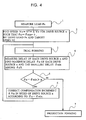
- step 1 of the flow chart a trial forming of a work-piece is performed.
- a load applied on each of the drive sources 60a, 60b, 60c and 60d engaged to the slide plate 40 is measured to obtain loads at each of descending displacements of the slide plate.
- a driving signal is supplied to each of the drive sources 60a, 60b, 60c and 60d to rotate the servo-motors and to descend the slide plate 40.
- the loads working on the slide plate are varied to make the slide plate 40 inclined.
- Descending progresses of the drive sources can be monitored by the descending displacements of the slide plate measured by the displacement measuring devices 50a, 50b, 50c and 50d provided adjacent to the drive sources, and a progress of a drive source that is delayed in progress can be hastened.
- Displacement at a portion of the slide plate at which each of the drive sources is provided is made same to make the slide plate horizontal and descended. Repeating these steps, the slide plate is descended until the end of the press-forming and then after the press-forming, the slide plate is returned to the original place to complete a cycle of the trial forming.
- the loads working on each of the drive sources change in magnitude of the loads and position of the loads like, for example, at displacement l 1 , P a1 is the largest and P d1 is the smallest, while P b2 is the largest and P d2 is the smallest at displacement l 2 . It is assumed that P am ⁇ P dm ⁇ P bm ⁇ P cm at displacement l m .
- the drive source 60c is most delayed in descending displacement among the drive sources and the delay is ⁇ c, while the drive source 60a is least delayed in descending displacement and the delay is ⁇ a.
- the vertical axis is an instructed displacement and the horizontal axis is a delay ⁇ of actual displacement from the instructed displacement of the slide plate near each of the drive sources.
- the relative delay becomes largest at l m and returns to zero at l m+1 . Since the load on the drive source 60a is smallest among the loads on respective drive sources at displacement l m and the delay in descending displacement of the drive source 60a is smallest, the drive source is set to a reference drive source.
- ⁇ a is set to ⁇ min.
- a target speed of the drive source 60a (reference drive source) that the smallest load is applied on in the displacement period of l m-1 to l m+1 is set to Vf.
- the target speed is a speed for a production forming of a drive source.
- step 2 speeds Vn (n: b, c and d) of each of the drive sources n are obtained to equalize delays of the drive sources with the delay ⁇ min of the drive source 60a, by using loads P am , P bm , P cm and P dm working on the drive sources 60a, 60b, 60c and 60d and the target speed Vf of the drive source 60a.
- a speed Vn of a drive source n that has the same delay ⁇ n as the delay ⁇ min of the drive source 60a is calculated as follows.
- the speed Vn obtained above for each of the drive sources n may be expressed as a sum of a target speed Vf of the reference drive source and a speed increment ⁇ Vn. It is preferable that a speed of each of the drive sources is set to 50 % to 90 % of the obtained increment ⁇ Vn in the trial forming in step 3. This is because the calculated speed Vn is reduced since the speed Vn calculated above is applied during the period of displacement l m-1 to displacement l m+1 , assuming that there is a uniform delay during the period.
- a speed increment is obtained by calculation here and there might be a risk in applying the calculated speed increment to a real press machine, it is better to use a less speed increment than that to avoid the risk.
- a drive source of the smallest load is used as the reference drive source in the explanation, another drive source may be a reference drive source.
- an increment ⁇ Vn might be negative and that should be taken care.
- step 3 delays of the drive sources are measured and, in step 4, the largest value ⁇ n of a delay for each of the drive sources n is obtained and the smallest value among the largest values is set to ⁇ min.
- step 5 the largest delay ⁇ n for each of the drive sources n is compared with the smallest value ⁇ min among the largest values ⁇ n's and, if the difference between ⁇ n and ⁇ min is more than a predetermined value ⁇ , the compensation increment ⁇ Vn used before is corrected in step 6, and steps 3, 4 and 5 are repeated.
- the value ⁇ for comparison of the difference between ⁇ n and ⁇ min is such an inclination that dies is not broken (for example, less than 100 ⁇ m)
- the criteria is less than 10 ⁇ m for increase of accuracy of products, specifically about 3 ⁇ m.
- step 5 If the difference between the largest delay ⁇ n for each of the drive sources n and the smallest delay value ⁇ min among the largest delays is less than or equal to the predetermined value ⁇ in the comparison of step 5, the flow goes to step 7 and a production forming of a work-piece is performed, using speeds of the drive sources obtained in a previous cycle.
Landscapes
- Engineering & Computer Science (AREA)
- Mechanical Engineering (AREA)
- Control Of Presses (AREA)
- Press Drives And Press Lines (AREA)
Claims (2)
- Ein Pressformverfahren umfassend die Schritte:Bereitstellen einer Pressmaschine, umfassendeine befestigte Platte,eine Gleitplatte (40), angeordnet um der festen Platte gegenüberzustehen und beweglich relativ zu der festen Platte, undeine Vielzahl von Antriebsquellen (60a, 60b, 60c, 60d), die jeweils einen Servomotor zum Antreiben der Gleitplatte (40) aufweisen, und die jeder eine Vielzahl von Eingriffsabschnitten (62a, 62b, 62c, 62d), die auf der Gleitplatte (40) positioniert sind, pressen, um die Gleitplatte (40) horizontal zu pressen,Messen einer Last, die auf jeder der Vielzahl von Antriebsquellen (60a, 60b, 60c, 60d) bei jeder absteigenden Verschiebung der Gleitplatte (40) wirkt, während die Gleitplatte (40) verschoben wird, um ein Werkstück presszuformen,Anwenden der Last an jeder der absteigenden Verschiebungen und eine Zielgeschwindigkeit zum Umformen im Produktionsprozess für eine der Vielzahl von Antriebsquellen (60a, 60b, 60c, 60d), wird als Referenzantriebsquelle betrachtet, an jeder der absteigenden Verschiebungen wird mit einer Funktion, die eine Verzögerung einer Antriebsquelle in Bezug auf eine angewiesenen Verschiebung in Form einer Geschwindigkeit der Antriebsquelle undeiner Last, die an der Antriebsquelle arbeitet, zeigt, eine Kompensationsgeschwindigkeit für jede der Vielzahl von Antriebsquellen (60a, 60b, 60c, 60d) berechnet, um eine Verzögerung für jede der Vielzahl von Antriebsquellen (60a, 60b, 60c, 60d) von der Referenzantriebsquelle zu eliminieren,Antreiben jeder der Vielzahl von Antriebsquellen (60a, 60b, 60c, 60d) mit der Ausgleichsgeschwindigkeit, um ein Werkstück in einer Probeformung presszuformen,Messen einer Verzögerung von jeder der Vielzahl von Antriebsquellen (60a, 60b, 60c, 60d) während der Probeformung, bis Verzögerungen anderer Antriebsquellen von der Referenzantriebsquelle nicht mehr als ein vorbestimmter Wert sind, Wiederholungskorrektur der Kompensationsgeschwindigkeit, der Probeformung und der Messung der Verzögerung während der Probeformung, undwenn die Verzögerungen der anderen Antriebsquellen von der Referenzantriebsquelle nicht größer als der vorbestimmte Wert werden, Pressformen von Werkstücken mit korrigierten jeweiligen Geschwindigkeiten der Vielzahl von Antriebsquellen (60a, 60b, 60c, 60d) beim Umformen im Produktionsprozess, die genannte Referenzantriebsquelle aus der Vielzahl von Antriebsquellen (60a, 60b, 60c, 60d) ist eine Antriebsquelle, an der die kleinste Last bei jeder der absteigenden Verschiebungen auftritt.
- Ein Pressformverfahren nach Anspruch 1, wobei die Kompensationsgeschwindigkeit (Vn) für eine Antriebsquelle (n) als Vf + ΔVn, ausgedrückt wird, in dem Vf eine Zielgeschwindigkeit für die Referenzantriebsquelle ist und ΔVn ist eine Geschwindigkeitserhöhung für die Referenzantriebsquelle von der Zielgeschwindigkeit (Vf) für die Kompensationsgeschwindigkeit (Vn), die unter Verwendung einer Funktion gerechnet wird, die eine Verzögerung einer Antriebsquelle in Form einer Geschwindigkeit der Antriebsquelle (n) zeigt und einer Last die auf der Antriebsquelle (n) wirkt und die Probeformung wird durch Antreiben jeder der Vielzahl von Antriebsquellen (60a, 60b, 60c, 60d) mit einer Geschwindigkeit von Vf + 50 bis 90% der oben berechneten Geschwindigkeitserhöhung durchgeführt.
Applications Claiming Priority (3)
| Application Number | Priority Date | Filing Date | Title |
|---|---|---|---|
| JP2002307935A JP4246470B2 (ja) | 2002-10-23 | 2002-10-23 | プレス成形方法 |
| JP2002307935 | 2002-10-23 | ||
| PCT/JP2003/012940 WO2004037531A1 (ja) | 2002-10-23 | 2003-10-09 | プレス成形方法 |
Publications (3)
| Publication Number | Publication Date |
|---|---|
| EP1555117A1 EP1555117A1 (de) | 2005-07-20 |
| EP1555117A4 EP1555117A4 (de) | 2011-04-06 |
| EP1555117B1 true EP1555117B1 (de) | 2017-07-12 |
Family
ID=32170954
Family Applications (1)
| Application Number | Title | Priority Date | Filing Date |
|---|---|---|---|
| EP03751397.5A Expired - Lifetime EP1555117B1 (de) | 2002-10-23 | 2003-10-09 | Pressformverfahren |
Country Status (8)
| Country | Link |
|---|---|
| US (1) | US7165490B2 (de) |
| EP (1) | EP1555117B1 (de) |
| JP (1) | JP4246470B2 (de) |
| KR (1) | KR100748013B1 (de) |
| CN (1) | CN1305662C (de) |
| CA (1) | CA2495920C (de) |
| TW (1) | TWI228449B (de) |
| WO (1) | WO2004037531A1 (de) |
Families Citing this family (6)
| Publication number | Priority date | Publication date | Assignee | Title |
|---|---|---|---|---|
| JP4995415B2 (ja) | 2004-09-09 | 2012-08-08 | 株式会社放電精密加工研究所 | プレス装置 |
| ES2452022T3 (es) * | 2006-02-06 | 2014-03-31 | Abb Research Ltd. | Sistema de línea de prensas y método |
| US10828858B2 (en) * | 2007-03-23 | 2020-11-10 | Gpcp Ip Holdings Llc | Servo-driven forming press |
| JP5799848B2 (ja) * | 2012-02-21 | 2015-10-28 | トヨタ自動車株式会社 | 多段プレス装置及び多段プレス方法 |
| JP6067397B2 (ja) * | 2013-02-01 | 2017-01-25 | トヨタ自動車株式会社 | 多軸サーボプレス装置及び多軸サーボプレス装置の制御方法 |
| US11141767B2 (en) * | 2018-07-30 | 2021-10-12 | Raytheon Technologies Corporation | Forging assembly having capacitance sensors |
Family Cites Families (11)
| Publication number | Priority date | Publication date | Assignee | Title |
|---|---|---|---|---|
| CA1275892C (en) * | 1986-10-10 | 1990-11-06 | Ronald Ballantyne | Hydraulic cylinder device for platen spacing indication and control |
| US4797831A (en) * | 1986-11-18 | 1989-01-10 | Cincinnati Incorporated | Apparatus for synchronizing cylinder position in a multiple cylinder hydraulic press brake |
| JP2705591B2 (ja) * | 1994-10-04 | 1998-01-28 | 村田機械株式会社 | パンチ駆動制御装置 |
| CN1134351A (zh) * | 1995-04-28 | 1996-10-30 | Aida会田工程技术株式会社 | 机械式压力机 |
| EP0940196B1 (de) * | 1996-10-29 | 2002-05-22 | Komatsu Ltd. | Biegewinkelkorrekturverfahren und so hergestellte biegepresse |
| JP3853908B2 (ja) * | 1997-03-31 | 2006-12-06 | 株式会社小松製作所 | 複数ポイントサーボプレスの制御装置 |
| JP3818788B2 (ja) | 1998-03-16 | 2006-09-06 | 株式会社山田ドビー | プレス機のスライド制御装置 |
| JP3969850B2 (ja) * | 1998-06-22 | 2007-09-05 | 株式会社小松製作所 | 電動式ベンダの制御方法および制御装置 |
| JP2000015341A (ja) | 1998-07-02 | 2000-01-18 | Komatsu Ltd | プレスブレーキのラム制御方法および制御装置 |
| US6595122B1 (en) * | 1999-09-03 | 2003-07-22 | Komatsu, Ltd. | Slide inclination correcting method and slide inclination correcting apparatus in press machinery |
| JP3689010B2 (ja) | 2001-03-15 | 2005-08-31 | 株式会社放電精密加工研究所 | プレス機 |
-
2002
- 2002-10-23 JP JP2002307935A patent/JP4246470B2/ja not_active Expired - Lifetime
-
2003
- 2003-10-02 TW TW092127312A patent/TWI228449B/zh not_active IP Right Cessation
- 2003-10-09 US US10/524,321 patent/US7165490B2/en not_active Expired - Lifetime
- 2003-10-09 WO PCT/JP2003/012940 patent/WO2004037531A1/ja not_active Ceased
- 2003-10-09 CA CA002495920A patent/CA2495920C/en not_active Expired - Fee Related
- 2003-10-09 CN CNB2003801007366A patent/CN1305662C/zh not_active Expired - Lifetime
- 2003-10-09 EP EP03751397.5A patent/EP1555117B1/de not_active Expired - Lifetime
- 2003-10-22 KR KR1020030073705A patent/KR100748013B1/ko not_active Expired - Fee Related
Non-Patent Citations (1)
| Title |
|---|
| None * |
Also Published As
| Publication number | Publication date |
|---|---|
| KR20040036585A (ko) | 2004-04-30 |
| TWI228449B (en) | 2005-03-01 |
| US7165490B2 (en) | 2007-01-23 |
| TW200408532A (en) | 2004-06-01 |
| CA2495920C (en) | 2009-11-10 |
| CA2495920A1 (en) | 2004-05-06 |
| JP4246470B2 (ja) | 2009-04-02 |
| HK1083609A1 (en) | 2006-07-07 |
| WO2004037531A1 (ja) | 2004-05-06 |
| US20050235844A1 (en) | 2005-10-27 |
| CN1694800A (zh) | 2005-11-09 |
| EP1555117A4 (de) | 2011-04-06 |
| JP2004141902A (ja) | 2004-05-20 |
| EP1555117A1 (de) | 2005-07-20 |
| CN1305662C (zh) | 2007-03-21 |
| KR100748013B1 (ko) | 2007-08-09 |
Similar Documents
| Publication | Publication Date | Title |
|---|---|---|
| EP1240999B1 (de) | Pressformvorrichtung | |
| CA2452895C (en) | Press forming machine | |
| EP1555117B1 (de) | Pressformverfahren | |
| EP1555116B1 (de) | Pressformverfahren | |
| CA2522174C (en) | Press forming machine | |
| JP4034685B2 (ja) | プレス成形方法 | |
| HK1068307B (en) | Press | |
| HK1083609B (en) | Press forming method | |
| HK1091169B (en) | Press-forming machine | |
| HK1083608B (en) | Press forming method |
Legal Events
| Date | Code | Title | Description |
|---|---|---|---|
| PUAI | Public reference made under article 153(3) epc to a published international application that has entered the european phase |
Free format text: ORIGINAL CODE: 0009012 |
|
| 17P | Request for examination filed |
Effective date: 20050309 |
|
| AK | Designated contracting states |
Kind code of ref document: A1 Designated state(s): DE FR GB IT |
|
| A4 | Supplementary search report drawn up and despatched |
Effective date: 20110304 |
|
| 17Q | First examination report despatched |
Effective date: 20111221 |
|
| REG | Reference to a national code |
Ref country code: DE Ref legal event code: R079 Ref document number: 60350404 Country of ref document: DE Free format text: PREVIOUS MAIN CLASS: B30B0015140000 Ipc: B30B0001180000 |
|
| RIC1 | Information provided on ipc code assigned before grant |
Ipc: B30B 15/24 20060101ALI20160413BHEP Ipc: B30B 15/14 20060101ALI20160413BHEP Ipc: B30B 1/18 20060101AFI20160413BHEP |
|
| GRAP | Despatch of communication of intention to grant a patent |
Free format text: ORIGINAL CODE: EPIDOSNIGR1 |
|
| INTG | Intention to grant announced |
Effective date: 20170105 |
|
| GRAS | Grant fee paid |
Free format text: ORIGINAL CODE: EPIDOSNIGR3 |
|
| GRAJ | Information related to disapproval of communication of intention to grant by the applicant or resumption of examination proceedings by the epo deleted |
Free format text: ORIGINAL CODE: EPIDOSDIGR1 |
|
| GRAL | Information related to payment of fee for publishing/printing deleted |
Free format text: ORIGINAL CODE: EPIDOSDIGR3 |
|
| GRAP | Despatch of communication of intention to grant a patent |
Free format text: ORIGINAL CODE: EPIDOSNIGR1 |
|
| GRAJ | Information related to disapproval of communication of intention to grant by the applicant or resumption of examination proceedings by the epo deleted |
Free format text: ORIGINAL CODE: EPIDOSDIGR1 |
|
| GRAL | Information related to payment of fee for publishing/printing deleted |
Free format text: ORIGINAL CODE: EPIDOSDIGR3 |
|
| GRAR | Information related to intention to grant a patent recorded |
Free format text: ORIGINAL CODE: EPIDOSNIGR71 |
|
| GRAA | (expected) grant |
Free format text: ORIGINAL CODE: 0009210 |
|
| INTC | Intention to grant announced (deleted) | ||
| INTC | Intention to grant announced (deleted) | ||
| INTG | Intention to grant announced |
Effective date: 20170601 |
|
| AK | Designated contracting states |
Kind code of ref document: B1 Designated state(s): DE FR GB IT |
|
| REG | Reference to a national code |
Ref country code: GB Ref legal event code: FG4D |
|
| REG | Reference to a national code |
Ref country code: DE Ref legal event code: R096 Ref document number: 60350404 Country of ref document: DE |
|
| REG | Reference to a national code |
Ref country code: FR Ref legal event code: PLFP Year of fee payment: 15 |
|
| REG | Reference to a national code |
Ref country code: DE Ref legal event code: R097 Ref document number: 60350404 Country of ref document: DE |
|
| PLBE | No opposition filed within time limit |
Free format text: ORIGINAL CODE: 0009261 |
|
| STAA | Information on the status of an ep patent application or granted ep patent |
Free format text: STATUS: NO OPPOSITION FILED WITHIN TIME LIMIT |
|
| 26N | No opposition filed |
Effective date: 20180413 |
|
| GBPC | Gb: european patent ceased through non-payment of renewal fee |
Effective date: 20171012 |
|
| PG25 | Lapsed in a contracting state [announced via postgrant information from national office to epo] |
Ref country code: GB Free format text: LAPSE BECAUSE OF NON-PAYMENT OF DUE FEES Effective date: 20171012 |
|
| REG | Reference to a national code |
Ref country code: FR Ref legal event code: PLFP Year of fee payment: 16 |
|
| PGFP | Annual fee paid to national office [announced via postgrant information from national office to epo] |
Ref country code: FR Payment date: 20221028 Year of fee payment: 20 |
|
| PGFP | Annual fee paid to national office [announced via postgrant information from national office to epo] |
Ref country code: IT Payment date: 20221026 Year of fee payment: 20 Ref country code: DE Payment date: 20220620 Year of fee payment: 20 |
|
| REG | Reference to a national code |
Ref country code: DE Ref legal event code: R071 Ref document number: 60350404 Country of ref document: DE |