EP1555084A1 - Machine-outil avec dispositifs de serrage coulissants en longueur avec des moyens moteurs propres - Google Patents
Machine-outil avec dispositifs de serrage coulissants en longueur avec des moyens moteurs propres Download PDFInfo
- Publication number
- EP1555084A1 EP1555084A1 EP04075022A EP04075022A EP1555084A1 EP 1555084 A1 EP1555084 A1 EP 1555084A1 EP 04075022 A EP04075022 A EP 04075022A EP 04075022 A EP04075022 A EP 04075022A EP 1555084 A1 EP1555084 A1 EP 1555084A1
- Authority
- EP
- European Patent Office
- Prior art keywords
- clamps
- clamp
- improved device
- frame
- driving means
- Prior art date
- Legal status (The legal status is an assumption and is not a legal conclusion. Google has not performed a legal analysis and makes no representation as to the accuracy of the status listed.)
- Withdrawn
Links
Images


Classifications
-
- B—PERFORMING OPERATIONS; TRANSPORTING
- B23—MACHINE TOOLS; METAL-WORKING NOT OTHERWISE PROVIDED FOR
- B23Q—DETAILS, COMPONENTS, OR ACCESSORIES FOR MACHINE TOOLS, e.g. ARRANGEMENTS FOR COPYING OR CONTROLLING; MACHINE TOOLS IN GENERAL CHARACTERISED BY THE CONSTRUCTION OF PARTICULAR DETAILS OR COMPONENTS; COMBINATIONS OR ASSOCIATIONS OF METAL-WORKING MACHINES, NOT DIRECTED TO A PARTICULAR RESULT
- B23Q1/00—Members which are comprised in the general build-up of a form of machine, particularly relatively large fixed members
- B23Q1/25—Movable or adjustable work or tool supports
- B23Q1/44—Movable or adjustable work or tool supports using particular mechanisms
- B23Q1/56—Movable or adjustable work or tool supports using particular mechanisms with sliding pairs only, the sliding pairs being the first two elements of the mechanism
- B23Q1/60—Movable or adjustable work or tool supports using particular mechanisms with sliding pairs only, the sliding pairs being the first two elements of the mechanism two sliding pairs only, the sliding pairs being the first two elements of the mechanism
- B23Q1/62—Movable or adjustable work or tool supports using particular mechanisms with sliding pairs only, the sliding pairs being the first two elements of the mechanism two sliding pairs only, the sliding pairs being the first two elements of the mechanism with perpendicular axes, e.g. cross-slides
- B23Q1/621—Movable or adjustable work or tool supports using particular mechanisms with sliding pairs only, the sliding pairs being the first two elements of the mechanism two sliding pairs only, the sliding pairs being the first two elements of the mechanism with perpendicular axes, e.g. cross-slides a single sliding pair followed perpendicularly by a single sliding pair
-
- B—PERFORMING OPERATIONS; TRANSPORTING
- B23—MACHINE TOOLS; METAL-WORKING NOT OTHERWISE PROVIDED FOR
- B23Q—DETAILS, COMPONENTS, OR ACCESSORIES FOR MACHINE TOOLS, e.g. ARRANGEMENTS FOR COPYING OR CONTROLLING; MACHINE TOOLS IN GENERAL CHARACTERISED BY THE CONSTRUCTION OF PARTICULAR DETAILS OR COMPONENTS; COMBINATIONS OR ASSOCIATIONS OF METAL-WORKING MACHINES, NOT DIRECTED TO A PARTICULAR RESULT
- B23Q3/00—Devices holding, supporting, or positioning work or tools, of a kind normally removable from the machine
- B23Q3/02—Devices holding, supporting, or positioning work or tools, of a kind normally removable from the machine for mounting on a work-table, tool-slide, or analogous part
- B23Q3/06—Work-clamping means
- B23Q3/062—Work-clamping means adapted for holding workpieces having a special form or being made from a special material
- B23Q3/064—Work-clamping means adapted for holding workpieces having a special form or being made from a special material for holding elongated workpieces, e.g. pipes, bars or profiles
-
- B—PERFORMING OPERATIONS; TRANSPORTING
- B25—HAND TOOLS; PORTABLE POWER-DRIVEN TOOLS; MANIPULATORS
- B25B—TOOLS OR BENCH DEVICES NOT OTHERWISE PROVIDED FOR, FOR FASTENING, CONNECTING, DISENGAGING OR HOLDING
- B25B1/00—Vices
- B25B1/06—Arrangements for positively actuating jaws
- B25B1/18—Arrangements for positively actuating jaws motor driven, e.g. with fluid drive, with or without provision for manual actuation
-
- B—PERFORMING OPERATIONS; TRANSPORTING
- B25—HAND TOOLS; PORTABLE POWER-DRIVEN TOOLS; MANIPULATORS
- B25B—TOOLS OR BENCH DEVICES NOT OTHERWISE PROVIDED FOR, FOR FASTENING, CONNECTING, DISENGAGING OR HOLDING
- B25B1/00—Vices
- B25B1/24—Details, e.g. jaws of special shape, slideways
- B25B1/2405—Construction of the jaws
Definitions
- the present invention concerns an improved device for machining and finishing parts, more specifically for milling, drilling, tapping, punching and sawing a variety of parts like for example profiles in metal, non-ferro and other heat-resistant materials, such as PVC.
- Such devices for machining parts are up to now essentially composed of a machining apparatus with at least one working tool positioned alongside a longitudinal frame, one or more clamps with at least two claws for clamping the parts to be machined, which clamps are provided in a slidable manner on guides mounted on said frame following the longitudinal direction of this frame, whereby at least one claw of each clamp is provided on a slide which is mounted on guides extending in a direction transversal to the longitudinal direction of the frame and whereby this slide is provided with pressure means to clamp the concerned part.
- the clamps Prior to clamping the part to be machined, the clamps are moved to their respective desired positions along the frame.
- the clamps are actually moved along the longitudinal direction of the frame, either manually by the operator of the device, either automatically by an outside positioning system which can move the clamps individually one at the time.
- a disadvantage of the existing devices is that the positioning of the clamps take up a lot of production time since the clamps have to be moved one by one, hence limiting the production capacity of the device.
- Another disadvantage is that with such a known device the parts have to be prepared and machined in a successive manner and that such a device does not allow to already prepare the next part to be machined before the previous part has completely been machined and has been removed from the device.
- clamps are needed with different clamping width. Indeed, in order to avoid that fingers are caught between the clamps and the part to be machined, clamps must be chosen with a maximum clamping width which is slightly larger than the width of the concerned part at the spot of clamping.
- the invention aims an improved device for machining parts which remedies one or more of the above mentioned disadvantages.
- clamps can simultaneously be moved on an individual basis, each to their respective desired clamping spots.
- the clamps can also be moved simultaneously in a synchronised manner, so that when all the clamps which hold a particular part, are activated in such a synchronised way, the concerned part can be moved on the frame, for instance out of the working area towards a first preparation area on one side of the frame, so that the working area is cleared for machining the next part which in the meanwhile has been prepared in a second preparation area on the other side of the frame and which can be moved to the working area in a similar way by simultaneously activating the clamps which are holding said part.
- This means that the production capacity of the device is even more improved with respect to the known devices.
- the device is provided with means to adapt the maximum clamping width of the clamp, so that the same clamp can be used for clamping parts with different sizes.
- the improved device 1 for machining parts according to the invention is essentially composed of a longitudinal frame 2 with a plurality of clamps 3 for clamping a construction part 4 to be machined.
- a machining apparatus 5 with one or more working tools like drills, taps, punches or the like is positioned alongside the frame 2 and is in this case mounted on tracks 6 which are parallel to the frame 2 and which extend over the length of a central working area 7 which is limited by a fence 8 or the like and which also separates a first preparation area 9 on one end of the frame 2 from a second preparation area 10 on the opposite end of the frame 2.
- each clamp 3 is mounted in a slidable manner on guides 11 mounted on said frame 2 following the longitudinal direction of this frame 2.
- Each clamp 3 is according to the invention equipped with its own driving means 12 to move said clamp 3 in the longitudinal direction of the frame 2, whereby these driving means 12 are formed by a motor 13 which is fitted onto said clamp 3 and by a gear 14 which is fixed on the shaft 15 of the motor 13 and which meshes up with a fixed gear lath 16 which extends in the longitudinal direction of the frame 2 and which is secured to the frame 2 by means of a support 17.
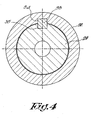
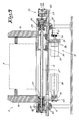
- Each clamp 3 possesses two claws, respectively a first claw 18 which is fixed on the clamp 3, and a second claw 19 which is provided on a slide 20 which is slidably mounted on guides 21 extending in a direction transversal to the longitudinal direction of the frame 2.
- the slide 20 is provided with pressure means 22 to clamp a part 4 to be machined, whereby these pressure means 22 are in this case formed by a pneumatic or hydraulic cylinder 23 fixed with its body 24 to the clamp 3 and provided with a piston 25 and a protruding cylinder rod 26 which is fixed to a pressure rod 27 extending parallel to the above mentioned guides 21, this pressure rod 27 being connected to the slide 20 of the slidable claw 19.
- these pressure means 22 are in this case formed by a pneumatic or hydraulic cylinder 23 fixed with its body 24 to the clamp 3 and provided with a piston 25 and a protruding cylinder rod 26 which is fixed to a pressure rod 27 extending parallel to the above mentioned guides 21, this pressure rod 27 being connected to the slide 20 of the slidable claw 19.
- the pressure rod 27 is ratatably supported with each of its extremities in a sleeve 28, 29 respectively, by means of bearings 30, whereby both sleeves 28 and 29 are slidably mounted in concentric bushes 31 and 32 fixed on the clamp 3.
- the sleeves 28 and 29 are provided with means to prevent them from turning in said bushes 31 and 32, whereby these means are formed by a bar 33 which is mounted in between the sleeves 28-29 and the bushes 31-32, more particularly in axially extending grooves 34 in the sleeves 28-29 and in axially extending grooves 35 in the bushes 30-31.
- the pressure rod 27 of the clamp 3 is a threaded rod which extends through threaded holes 36 in the slide 20 of the slidably mounted claw 19 and whereby this threaded rod is provided with driving means which in this case are formed by a first pulley 37 fixed on said rod 27; by a motor 38 which is fixed with its housing on one of the supporting sleeves 29 and which carries a second pulley 39; and by a belt 40 which is mounted on both pulleys 37-39.
- the improved device according to the invention is provided with a central control unit which is not shown in the drawing and which is meant for control of the driving means 12 of said clamps, as well as of the pressure means 22 and of the means to change the maximum clamping width of each clamp 3.
- This control unit is such that it allows for individual control of each of the clamps 3 and that it allows for simultaneous and synchronised control of two or more, preferably of all of said clamps.
- FIG 1 a situation is represented whereby a part 4 to be machined is positioned in the working area 7 and is fixed in position on the frame 2 by means of a plurality of clamps 3.
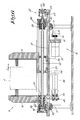
- the part 4 is clamped in between the claws 18-19 of each clamp 3 by first actuating the motor 38 in order to rotate the threaded rod 27 and to move the slide 20 with the claw 19 into a position as indicated in figure 3, in order to adapt the maximum clamping width of the clamp in such a way that the clearance S between the part 4 and the claws 18-19 is less than a predetermined value, which preferably is less then the thickness of a finger, so that the danger of fingers getting caught between the part 4 and the clamp 3 is minimised.
- a predetermined value which preferably is less then the thickness of a finger
- the maximum clamping width between the claws 18-19 can be reduced by actuating the motor 38, thereby further approaching the claws 18-19 to each other.
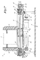
- the part 4 is clamped between the claws 18-19, by actuating the pressure means 22, i.e. the cylinder 23, in order to push the pressure rod 27 and the slide 20 connected to this rod 27 towards the part 4 as is represented in figure 5 and in figure 7 for two parts with different sizes of its cross-section.
- one or more clamps 3 can be moved from one spot to another in order to make access for the working tool.
- all the clamps 3 can be moved simultaneously with the same speed and in the same direction in order to move the part 4 to the empty preparation area 10, in order to remove the finished part 4.
- part 4 in the working area 7 can be divided into several smaller parts by sawing or any other operation and that these smaller parts can subsequently be moved apart in the longitudinal direction for machining the extremities of these smaller parts, which is not possible with existing devices for machining parts.
Priority Applications (1)
| Application Number | Priority Date | Filing Date | Title |
|---|---|---|---|
| EP04075022A EP1555084A1 (fr) | 2004-01-13 | 2004-01-13 | Machine-outil avec dispositifs de serrage coulissants en longueur avec des moyens moteurs propres |
Applications Claiming Priority (1)
| Application Number | Priority Date | Filing Date | Title |
|---|---|---|---|
| EP04075022A EP1555084A1 (fr) | 2004-01-13 | 2004-01-13 | Machine-outil avec dispositifs de serrage coulissants en longueur avec des moyens moteurs propres |
Publications (1)
| Publication Number | Publication Date |
|---|---|
| EP1555084A1 true EP1555084A1 (fr) | 2005-07-20 |
Family
ID=34610198
Family Applications (1)
| Application Number | Title | Priority Date | Filing Date |
|---|---|---|---|
| EP04075022A Withdrawn EP1555084A1 (fr) | 2004-01-13 | 2004-01-13 | Machine-outil avec dispositifs de serrage coulissants en longueur avec des moyens moteurs propres |
Country Status (1)
| Country | Link |
|---|---|
| EP (1) | EP1555084A1 (fr) |
Cited By (21)
| Publication number | Priority date | Publication date | Assignee | Title |
|---|---|---|---|---|
| EP2246150A3 (fr) * | 2009-04-28 | 2011-04-06 | Mubea Systems, Société Anonyme | Machine-outil à 4 axes |
| CN102350647A (zh) * | 2011-08-22 | 2012-02-15 | 重庆银钢汽车配件制造有限责任公司 | 夹具及具有该夹具的铣端面钻中心孔机床 |
| CN102366897A (zh) * | 2011-09-14 | 2012-03-07 | 常州常瑞天力动力机械有限公司 | 夹紧装置 |
| DE102010050127A1 (de) | 2010-11-03 | 2012-05-03 | Mubea Systems, S.A. | Vorrichtung zum Bearbeiten eines großformatigen, dünnwandigen Werkstücks |
| WO2014071486A1 (fr) | 2012-11-12 | 2014-05-15 | Whirlpool S.A. | Dispositif automatique pour la fixation de pièces |
| CN103817478A (zh) * | 2014-03-06 | 2014-05-28 | 南通通洋机电制造有限公司 | 电梯轿厢平台焊接工装 |
| CN104942147A (zh) * | 2015-06-18 | 2015-09-30 | 昆山—邦泰汽车零部件制造有限公司 | 多方位定位冲压模具 |
| CN105108533A (zh) * | 2015-09-30 | 2015-12-02 | 苏州龙行洲实业有限公司 | 一种五金件钻孔固定治具 |
| CN105382588A (zh) * | 2015-12-27 | 2016-03-09 | 天津塔尔森科技发展有限公司 | 一种钢结构连接板钻孔夹具 |
| CN106064315A (zh) * | 2016-08-22 | 2016-11-02 | 张民胜 | 一种数控机床的夹紧装置 |
| EP3098024A1 (fr) | 2015-05-29 | 2016-11-30 | Kaltenbach GmbH + Co. KG | Dispositif de serrage |
| CN108637742A (zh) * | 2018-07-20 | 2018-10-12 | 高邮市力博机床附件厂 | 一种机床加工用便于工件的固定装置 |
| CN108838971A (zh) * | 2018-07-23 | 2018-11-20 | 盐城市金发机械厂 | 一种变速箱维修用检修台 |
| CN109719215A (zh) * | 2019-03-08 | 2019-05-07 | 贵州电网有限责任公司 | 一种液压管压接防弯曲变形装置 |
| CN110842599A (zh) * | 2019-11-20 | 2020-02-28 | 益模钢模五金(深圳)有限公司 | 一种便于对工件进行固定的铣床 |
| IT201900013017A1 (it) * | 2019-07-26 | 2021-01-26 | F O M Ind S R L | Macchina per la lavorazione di profilati di alluminio, leghe leggere, pvc o simili |
| EP3932613A1 (fr) * | 2020-08-10 | 2022-01-05 | Rene Westphal | Procédé et dispositif de replacement sans contact d'une barre de serrage sur un centre d'usinage cnc |
| CN114165697A (zh) * | 2022-02-10 | 2022-03-11 | 江苏中尚机器人科技有限公司 | 一种电子设备的紧定器 |
| CN114505796A (zh) * | 2022-02-18 | 2022-05-17 | 桂林芯隆科技有限公司 | 半导体激光器芯片端面镀膜夹紧夹具 |
| WO2022252304A1 (fr) * | 2021-05-31 | 2022-12-08 | 南京蹑波物联网科技有限公司 | Dispositif d'assemblage ayant un robot industriel et procédé d'assemblage |
| CN117583892A (zh) * | 2024-01-19 | 2024-02-23 | 奥迪(山东)电机有限公司 | 一种发动机机壳加工卧式数控机床 |
Citations (3)
| Publication number | Priority date | Publication date | Assignee | Title |
|---|---|---|---|---|
| DE2915380A1 (de) * | 1979-04-14 | 1980-10-16 | Hegenscheidt Gmbh Wilhelm | Verfahren zum einspannen rohrfoermiger werkstuecke auf tiefbohrmaschinen |
| US5957638A (en) * | 1996-02-04 | 1999-09-28 | Winkler; Siegbert | Apparatus for machining of bar material, profiles and the like |
| EP1040891A1 (fr) * | 1999-03-17 | 2000-10-04 | ME.C.AL. S.n.c. di MESCHINI ROSELLA | Poste de travail avec plusieurs dispositifs de serrage pour le serrage d'une pièce |
-
2004
- 2004-01-13 EP EP04075022A patent/EP1555084A1/fr not_active Withdrawn
Patent Citations (3)
| Publication number | Priority date | Publication date | Assignee | Title |
|---|---|---|---|---|
| DE2915380A1 (de) * | 1979-04-14 | 1980-10-16 | Hegenscheidt Gmbh Wilhelm | Verfahren zum einspannen rohrfoermiger werkstuecke auf tiefbohrmaschinen |
| US5957638A (en) * | 1996-02-04 | 1999-09-28 | Winkler; Siegbert | Apparatus for machining of bar material, profiles and the like |
| EP1040891A1 (fr) * | 1999-03-17 | 2000-10-04 | ME.C.AL. S.n.c. di MESCHINI ROSELLA | Poste de travail avec plusieurs dispositifs de serrage pour le serrage d'une pièce |
Cited By (29)
| Publication number | Priority date | Publication date | Assignee | Title |
|---|---|---|---|---|
| EP2246150A3 (fr) * | 2009-04-28 | 2011-04-06 | Mubea Systems, Société Anonyme | Machine-outil à 4 axes |
| DE102010050127A1 (de) | 2010-11-03 | 2012-05-03 | Mubea Systems, S.A. | Vorrichtung zum Bearbeiten eines großformatigen, dünnwandigen Werkstücks |
| WO2012059194A1 (fr) | 2010-11-03 | 2012-05-10 | Mubea Systems S.A. | Dispositif pour usiner une pièce de grand format, à paroi mince |
| CN102350647A (zh) * | 2011-08-22 | 2012-02-15 | 重庆银钢汽车配件制造有限责任公司 | 夹具及具有该夹具的铣端面钻中心孔机床 |
| CN102350647B (zh) * | 2011-08-22 | 2013-08-07 | 四川银钢一通凸轮轴股份有限公司 | 夹具及具有该夹具的铣端面钻中心孔机床 |
| CN102366897A (zh) * | 2011-09-14 | 2012-03-07 | 常州常瑞天力动力机械有限公司 | 夹紧装置 |
| WO2014071486A1 (fr) | 2012-11-12 | 2014-05-15 | Whirlpool S.A. | Dispositif automatique pour la fixation de pièces |
| CN103817478A (zh) * | 2014-03-06 | 2014-05-28 | 南通通洋机电制造有限公司 | 电梯轿厢平台焊接工装 |
| EP3098024A1 (fr) | 2015-05-29 | 2016-11-30 | Kaltenbach GmbH + Co. KG | Dispositif de serrage |
| DE102015108541A1 (de) | 2015-05-29 | 2016-12-01 | Kaltenbach Gmbh + Co. Kg | Spannvorrichtung |
| CN104942147A (zh) * | 2015-06-18 | 2015-09-30 | 昆山—邦泰汽车零部件制造有限公司 | 多方位定位冲压模具 |
| CN105108533B (zh) * | 2015-09-30 | 2017-09-05 | 苏州龙行洲实业有限公司 | 一种五金件钻孔固定治具 |
| CN105108533A (zh) * | 2015-09-30 | 2015-12-02 | 苏州龙行洲实业有限公司 | 一种五金件钻孔固定治具 |
| CN105382588A (zh) * | 2015-12-27 | 2016-03-09 | 天津塔尔森科技发展有限公司 | 一种钢结构连接板钻孔夹具 |
| CN106064315A (zh) * | 2016-08-22 | 2016-11-02 | 张民胜 | 一种数控机床的夹紧装置 |
| CN108637742A (zh) * | 2018-07-20 | 2018-10-12 | 高邮市力博机床附件厂 | 一种机床加工用便于工件的固定装置 |
| CN108838971A (zh) * | 2018-07-23 | 2018-11-20 | 盐城市金发机械厂 | 一种变速箱维修用检修台 |
| CN109719215A (zh) * | 2019-03-08 | 2019-05-07 | 贵州电网有限责任公司 | 一种液压管压接防弯曲变形装置 |
| CN109719215B (zh) * | 2019-03-08 | 2024-04-16 | 贵州电网有限责任公司 | 一种液压管压接防弯曲变形装置 |
| IT201900013017A1 (it) * | 2019-07-26 | 2021-01-26 | F O M Ind S R L | Macchina per la lavorazione di profilati di alluminio, leghe leggere, pvc o simili |
| EP3769907A1 (fr) * | 2019-07-26 | 2021-01-27 | F.O.M. Industrie S.r.l. | Machine pour traiter des barres de section en aluminium, alliages légers, pvc ou similaire |
| CN110842599B (zh) * | 2019-11-20 | 2020-10-27 | 益模钢模五金(深圳)有限公司 | 一种便于对工件进行固定的铣床 |
| CN110842599A (zh) * | 2019-11-20 | 2020-02-28 | 益模钢模五金(深圳)有限公司 | 一种便于对工件进行固定的铣床 |
| EP3932613A1 (fr) * | 2020-08-10 | 2022-01-05 | Rene Westphal | Procédé et dispositif de replacement sans contact d'une barre de serrage sur un centre d'usinage cnc |
| WO2022252304A1 (fr) * | 2021-05-31 | 2022-12-08 | 南京蹑波物联网科技有限公司 | Dispositif d'assemblage ayant un robot industriel et procédé d'assemblage |
| CN114165697A (zh) * | 2022-02-10 | 2022-03-11 | 江苏中尚机器人科技有限公司 | 一种电子设备的紧定器 |
| CN114505796A (zh) * | 2022-02-18 | 2022-05-17 | 桂林芯隆科技有限公司 | 半导体激光器芯片端面镀膜夹紧夹具 |
| CN117583892A (zh) * | 2024-01-19 | 2024-02-23 | 奥迪(山东)电机有限公司 | 一种发动机机壳加工卧式数控机床 |
| CN117583892B (zh) * | 2024-01-19 | 2024-04-09 | 奥迪(山东)电机有限公司 | 一种发动机机壳加工卧式数控机床 |
Similar Documents
| Publication | Publication Date | Title |
|---|---|---|
| EP1555084A1 (fr) | Machine-outil avec dispositifs de serrage coulissants en longueur avec des moyens moteurs propres | |
| DE10029749C2 (de) | Vorrichtung und Verfahren zum Beschicken und/oder Entnehmen von Werkstücken an einer Werkzeugmaschine | |
| DE102005055972B3 (de) | Werkzeugmaschine | |
| EP1600254B1 (fr) | Unité d'avance pour machine à usiner des pièces et méthode pour usiner ces pièces | |
| DE19533320C2 (de) | Rundtaktmaschine | |
| EP0654318A1 (fr) | Machine pour la finition de flancs de dents des pièces sous forme de roue dentée en utilisant un outil à denture intérieure | |
| DE2642719B2 (de) | Verfahren und Schalttellermaschinen zum Herstellen von Werkstücken mit drehbearbeiteter Mantelfläche | |
| DE60205939T2 (de) | Bearbeitungsmaschine für langgestreckte profile | |
| EP2279819B1 (fr) | Dispositif d'usinage mécanique de pièces tubulaires ou en forme de tiges | |
| DE102004034911A1 (de) | Werkzeugmaschine und damit ausgestattete Bearbeitungslinie | |
| EP1413395A1 (fr) | Machine-outil | |
| DE3010934C2 (fr) | ||
| DE2015795A1 (de) | Verfahren und Vorrichtung zum Schneiden von Rohren und zum Abfasen der Schnittkanten | |
| CH649489A5 (de) | Werkstueck-handhabungseinrichtung fuer werkzeugmaschinen, insbesondere drehautomaten. | |
| CN211464944U (zh) | 一种双工位全自动接管加工装置 | |
| EP1985409A1 (fr) | Machine transfert flexible avec porte-pièces mobiles | |
| DE3245850C2 (fr) | ||
| US5465471A (en) | Apparatus for machining bars | |
| CH659017A5 (de) | Mehrwerkstueck-drehautomat. | |
| WO2018096444A1 (fr) | Tour et procédé permettant de faire tourner des pièces à usiner | |
| CH697293B1 (de) | Drehmaschine, insbesondere Mehrspindeldrehautomat. | |
| DE102010018610B4 (de) | Außen-Räummaschine für Schlosskerne und Verfahren zum Außenräumen | |
| DE19826885A1 (de) | Werkstückträger, insbesondere zur Aufnahme runder oder symmetrischer Formteile | |
| DE102007048083B4 (de) | Anordnung von Bearbeitungszonen | |
| DE102004059054B4 (de) | Vorrichtung mit mindestens zwei nebeneinander angeordneten Bearbeitungsmaschinen |
Legal Events
| Date | Code | Title | Description |
|---|---|---|---|
| PUAI | Public reference made under article 153(3) epc to a published international application that has entered the european phase |
Free format text: ORIGINAL CODE: 0009012 |
|
| AK | Designated contracting states |
Kind code of ref document: A1 Designated state(s): AT BE BG CH CY CZ DE DK EE ES FI FR GB GR HU IE IT LI LU MC NL PT RO SE SI SK TR |
|
| AX | Request for extension of the european patent |
Extension state: AL LT LV MK |
|
| AKX | Designation fees paid | ||
| REG | Reference to a national code |
Ref country code: DE Ref legal event code: 8566 |
|
| STAA | Information on the status of an ep patent application or granted ep patent |
Free format text: STATUS: THE APPLICATION IS DEEMED TO BE WITHDRAWN |
|
| 18D | Application deemed to be withdrawn |
Effective date: 20060121 |