EP1554997B1 - Vorrichtung zur Begrenzung der Nahrungsaufnahme - Google Patents
Vorrichtung zur Begrenzung der Nahrungsaufnahme Download PDFInfo
- Publication number
- EP1554997B1 EP1554997B1 EP05075918A EP05075918A EP1554997B1 EP 1554997 B1 EP1554997 B1 EP 1554997B1 EP 05075918 A EP05075918 A EP 05075918A EP 05075918 A EP05075918 A EP 05075918A EP 1554997 B1 EP1554997 B1 EP 1554997B1
- Authority
- EP
- European Patent Office
- Prior art keywords
- energy
- restriction
- reservoir
- cavity
- signals
- Prior art date
- Legal status (The legal status is an assumption and is not a legal conclusion. Google has not performed a legal analysis and makes no representation as to the accuracy of the status listed.)
- Expired - Lifetime
Links
Images


Classifications
-
- A—HUMAN NECESSITIES
- A61—MEDICAL OR VETERINARY SCIENCE; HYGIENE
- A61F—FILTERS IMPLANTABLE INTO BLOOD VESSELS; PROSTHESES; DEVICES PROVIDING PATENCY TO, OR PREVENTING COLLAPSING OF, TUBULAR STRUCTURES OF THE BODY, e.g. STENTS; ORTHOPAEDIC, NURSING OR CONTRACEPTIVE DEVICES; FOMENTATION; TREATMENT OR PROTECTION OF EYES OR EARS; BANDAGES, DRESSINGS OR ABSORBENT PADS; FIRST-AID KITS
- A61F5/00—Orthopaedic methods or devices for non-surgical treatment of bones or joints; Nursing devices ; Anti-rape devices
- A61F5/0003—Apparatus for the treatment of obesity; Anti-eating devices
- A61F5/0013—Implantable devices or invasive measures
- A61F5/005—Gastric bands
- A61F5/0053—Gastric bands remotely adjustable
-
- A—HUMAN NECESSITIES
- A61—MEDICAL OR VETERINARY SCIENCE; HYGIENE
- A61F—FILTERS IMPLANTABLE INTO BLOOD VESSELS; PROSTHESES; DEVICES PROVIDING PATENCY TO, OR PREVENTING COLLAPSING OF, TUBULAR STRUCTURES OF THE BODY, e.g. STENTS; ORTHOPAEDIC, NURSING OR CONTRACEPTIVE DEVICES; FOMENTATION; TREATMENT OR PROTECTION OF EYES OR EARS; BANDAGES, DRESSINGS OR ABSORBENT PADS; FIRST-AID KITS
- A61F5/00—Orthopaedic methods or devices for non-surgical treatment of bones or joints; Nursing devices ; Anti-rape devices
- A61F5/0003—Apparatus for the treatment of obesity; Anti-eating devices
Definitions
- the present invention relates to a food intake restriction device for forming a stoma opening in the stomach or esophagus of a patient, the device comprising an elongated restriction member, forming means for forming the elongated restriction member into at least a substantially closed loop around the stomach or esophagus, said loop defining a restriction opening, and an adjustment means for adjustment of the restriction member in said loop to change the size of the restriction opening.
- patient includes an animal or a human being.
- Food intake restriction devices in the form of gastric banding devices, in which a band encircles a portion of a patient's stomach to restrict the food intake of the patient, have been used in surgery for morbid obesity to form a small gastric pouch above the band and a reduced stoma opening in the stomach. Although such a band is applied around the stomach to obtain an optimal stoma opening during surgery, some prior gastric banding devices are provided with an adjustment means enabling a minor post-operation adjustment of the size of the stoma opening. In all such prior art devices such as disclosed in U.S. Patent No. 4,592,339 , European Patent No.
- the adjustment means typically comprises an inflatable cavity in the band and an injection port in fluid connection with the inflatable cavity.
- the injection port is subcutaneously implanted to allow the addition of fluid to or withdrawal of fluid from the cavity by an injection needle penetrating the patient's skin into the injection port.
- the band is made of silicone rubber which is a material approved for implantation and the fluid is a liquid such as an isotonic salt solution.
- EP 0 876 808 A which qualifies as prior art under Art 54(3) EPC, discloses a device which includes an adjustable strap for implanting around the stomach.
- the strap has a variable volume cavity filled with a liquid.
- the volume of liquid in the cavity is adjusted by a system which includes a control box that is connected to the cavity and implanted in the patient's body.
- the control box contains a battery, an electronic control unit and an electrically driven pump.
- US 3,750,194 A discloses an apparatus for reversibly closing a body passage which uses an implantable fluid reservoir and a distensible member that is connected to the body passage.
- An implantable pump is connected to the fluid reservoir and the distensible member for pumping fluid from the reservoir to the distensible member to distend the distensible member and cause the reversible closing of the body passage.
- the bands of this type of prior art devices used for forming a stoma opening in a patient's stomach may eventually dislocate downwardly on the stomach and there is an increased risk of stoma stenosis due to a small range of adjustment of the band.
- the volume of the gastric pouch above the band increases in size up to ten times after operation. Therefore the pouch volume during surgery needs to be very small, approximately 7 ml.
- the stoma initially needs to be relatively large and later needs to be substantially reduced, as the pouch volume increases.
- the cavity in the band has to be relatively large and is defined by a thin flexible wall, normally made of silicone material.
- the size of the stoma opening has to be gradually reduced during the first year after surgery as the gastric pouch increases in size. As indicated above, the reduction of the stoma opening using the prior art implantable devices is achieved by adding liquid to the cavity of the band via the injection port to expand the band radially inwardly.
- a great disadvantage of repeatedly injecting liquid via the injection port is the increased risk of the patient getting an infection in the body area surrounding the injection port. If such an infection occurs the injection port has to be surgically removed from the patient. Moreover, such an infection might be spread along the tube interconnecting the injection port and the band to the stomach, causing even more serious complications. Thus, the stomach might be infected where it is in contact with the band, which might result in the band migrating through the wall of the stomach. Also, it is uncomfortable for the patient when the necessary, often many, post-operation adjustments of the stoma opening are carried out using an injection needle penetrating the skin of the patient into the injection port.
- An object of the invention is to provide a food intake restriction device for forming a stoma opening in the stomach or esophagus of a patient which does not require the use of an injection needle for accomplishing post-operation adjustments of the stoma opening.
- Another object of the invention is to provide a food intake restriction device for forming a stoma opening in the stomach or esophagus of a patient which permits post-operation adjustments that are comfortable for the patient.
- Yet another object of the invention is to provide a food intake restriction device for forming a stoma opening in the stomach or esophagus of a patient in which the risk of liquid leaking from the device is substantially reduced.
- an injection port for accomplishing necessary post-operation adjustments of the restriction opening to change the size of the stoma opening.
- an injection port connected to the reservoir may be provided for enabling, normally a single once-and-for-all, calibration of the predetermined amount of fluid in the reservoir.
- the adjustment means may be adapted to change the size of the restriction opening such that the outer circumferential confinement surface of the restriction member is changed, or, alternatively, is unchanged.
- the forming means may advantageously be adapted to form the restriction member into a loop having a predetermined size.
- a fluid distribution tube may be connected between the reservoir and the cavity in a manner so that the tube does not interfere with the forming means, such as coupling elements on the ends of the elongated restriction member. That is, the tube may be connected to the restriction member at a position spaced from the forming means.
- the hydraulic operation means comprise an activatable pump adapted to pump fluid between the reservoir and the cavity of the restriction member.
- the pump comprises a first activation member for activating the pump to pump fluid from the reservoir to the cavity of the restriction member, and a second activation member for activating the pump to pump fluid from the cavity to the reservoir.
- the first and second activation members may be operable by manual manipulation thereof, such as by manually pushing, pulling or rotating any of the activation members in one direction. At least one of the activation members is constructed to operate when subjected to an external pressure exceeding a predetermined magnitude.
- At least one of the first and second activating members may be operable by a device powered magnetically, hydraulically, or electrically (e.g . by an electric motor).
- the pump may pump fluid both to and away from the adjusment means or hydraulic means controlling the adjustment means.
- a mechanical solution is proposed in which it is possible to pump in both directions just by pushing an activating member in one direction.
- Another alternative is a pump pumping in only one direction and an adjustable valve to change the direction of fluid to either increase or decrease the amount of fluid in the reservoir. This valve may be manipulated either manually, mechanically, magnetically, or hydraulically. Any kind of motor could be used for the different operations as well as wireless remote solutions.
- a magnetic means may comprise a permanent magnet and a magnetic material reed switch, or other suitable known or conventional magnetic devices.
- the adjustment means may comprise a servo means.
- the servo means may comprise a hydraulic means, an electric control means, a magnetic means, mechanical means, or a manual manipulating means.
- the hydraulic means, electric control means, mechanical means or magnetic means may be activated by manual manipulating means. Using a servo system will save the use of force when adjusting the adjustment device which may be of importance in many applications.
- All systems according to the invention may be controlled by a wireless remote control means.
- a wireless remote control means for non-invasively controlling the hydraulic operation means.
- the remote control means may advantageously be capable of obtaining information on the size of the restriction opening and to command the hydraulic operation means to operate the adjustment means to adjust the restriction member in response to obtained information.
- the remote control means comprises means for wireless transfer of energy from outside the patient's body to energy consuming implantable components of the device.
- An implantable motor may suitably be provided for operating the hydraulic operation means and said means for wireless transfer of energy may be adapted to directly power the motor with transferred energy.
- the energy transferred by said means for transfer of energy may comprise wave signals, an electric field or a magnetic field.
- the wireless remote control means comprises separate signal transmitting means and implantable signal receiving means.
- the signal transmitting and signal receiving means may be adapted to transmit and receive signals in the form of digital pulses, which may comprise a magnetic or electric field.
- the signal transmitting and signal receiving means may be adapted to transmit and receive signals, which may comprise electromagnetic waves, sound waves or carrier waves for remote control signals.
- the receiving means may comprise a control unit adapted to control the hydraulic operation means in response to signals from the signal transmitting means.
- the food intake restriction device may further comprise an implantable energizer unit for providing energy to energy consuming components of the device to be implanted in the patient, such as electronic circuits and/or a motor for operating the hydraulic operation means.
- the control unit may be adapted to power such an implanted motor with energy provided by the energizer unit in response to signals received from the signal transmitting means.
- Any known or conventional signal transmitting or signal receiving device that is suitable for use with a human or mammal patient may be provided as the signal transmitting or signal receiving means.
- the signals may comprise electromagnetic waves, such as infrared light, visible light, laser light, micro waves, or sound waves, such as ultrasonic waves or infrasonic waves, or any other type of wave signals.
- the signals may also comprise electric or magnetic fields, or pulses. All of the above-mentioned signals may comprise digital signals.
- the motor may be any type of motor, such as a pneumatic, hydraulic or electric motor and the energizer unit may be adapted to power the motor with pressurized gas or liquid, or electrical energy, depending on the type of motor. Where the motor is an electric motor, it may power pneumatic or hydraulic equipment.
- the energizer unit may comprise a power supply and the control unit may be adapted to power the motor with energy from the power supply.
- the power supply is an electric power supply, such as a battery
- the motor is an electric motor.
- the battery also continuously powers the circuitry of the signal receiving means between the adjustment operations, in order to keep the signal receiving means prepared for receiving signals transmitted from the signal transmitting means.
- Ihe energizer unit may be adapted to transfer energy from the signals, as they are transmitted to the signal receiving means, into electric energy for powering the implanted electronic components.
- the energizer unit may be adapted to transfer the energy from the signals into direct or alternating current.
- the energizer unit may also power the motor with the transferred energy.
- the control unit is adapted to directly power the electric motor with electric energy, as the energizer unit transfers the signal energy into the electric energy.
- the energizer unit may comprise a rechargeable electric power supply for storing the electric energy obtained and the control unit be adapted to power the electric motor with energy from the rechargeable electric power supply in response to signals received from the signal transmitting means.
- the rechargeable power supply can be charged over a relatively long time (e.g . a few seconds up to a half hour) without powering the electric motor.
- the control unit powers the electric motor with energy from the charged power supply to operate the hydraulic operation means, so that a desired change of the patient's stoma opening is achieved. If the capacity of the power supply is insignificant to achieve the necessary adjustment in one single operating step, the above steps may conveniently be repeated until the desired adjustment is achieved.
- the electric power supply suitably comprises an inexpensive simple capacitor.
- the electric motor may be a stepping motor.
- the signal transmitting means may be adapted to transmit electromagnetic signals and the energizer unit be adapted to draw radiant energy from the electromagnetic wave signals, as they are transmitted to the signal receiving means, and transfer the radiant energy into electric energy.
- the energizer unit may comprise a battery, an electrically operable switch adapted to connect the battery to the signal receiving means in an "on" mode when the switch is powered and to keep the battery disconnected from the signal receiving means in a "standby” mode when the switch is unpowered, and a rechargeable electric power supply for powering the switch.
- the control unit may be adapted to power the electric motor with energy from the battery in response to signals received from the signal transmitting means, when the switch is in its "on” mode.
- the energizer unit may be adapted to transfer wave energy from the signals, as they are transmitted to the signal receiving means, into a current for charging the rechargeable electric power supply, which suitably is a capacitor.
- This embodiment is suited for adjustment means of the type that require relatively high power for their operation and has the advantage that the electronic circuitry of the signal receiving means does not have to be powered by the battery between adjustment operations. As a result, the life-time of the battery can be significantly prolonged.
- the signal transmitting means may be adapted to transmit electromagnetic wave signals and the energizer unit be adapted to draw radiant energy from the electromagnetic wave signals, as they are transmitted to the signal receiving means, and to transfer the radiant energy into said current.
- the energizer unit suitably comprises a coil of the signal receiving means for inducing an alternating current as electromagnetic wave signals are transmitted through the coil and a rectifier for rectifying the alternating current. The rectified current is used for charging the rechargeable power source.
- the signal transmitting and receiving means may solely be used for control signals and further signal transmitting and receiving means be provided for transferring signal energy to implanted components.
- the advantage is obtained that the two systems can be designed optimally for their respective purposes, namely to transmit control signals and to transfer energy from signals.
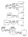
- Fig. 1A-D is a block diagram of four different embodiments of food intake restriction devices.
- Fig. 1A shows a restriction member in the form of a typically conventional inflatable band 2 (SAGB) for providing a stoma opening in the stomach or esophagus, a separate reservoir 4, a one way pump 6 and an alternate valve 8.
- Fig. 1B shows the band 2 and a fluid supply reservoir 10.
- Fig. 1C shows the band 2, a two way pump 12 and the reservoir 4.
- Fig. 1D shows a servo system with a first closed system controlling a second system.
- the servo system comprises the fluid supply reservoir 10 and a servo reservoir 14.
- the servo reservoir 14 controls a larger adjustable reservoir 16 which in connection with the band 2 varies the volume of a cavity in the band, which in turn varies a restriction opening 3 in the band 2.
- a band 2 and opening 3 are illustrated schematically in Fig. 8 .
- the conventional band 2 comprises an adjusttment means having an expandable/contractabe cavity 5 which is expanded or contracted by supplying hydraulic fluid ( e.g . from reservoir 4, 6, 10, or 16), and the band 2 may be sutured in place, illustrated schematically at 7 in Fig.8 .
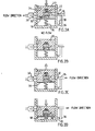
- Figs. 2A-D are cross-sectional views of a pump mechanism adapted to pump fluid in both directions only by mechanically pushing a separate sealing wall portion 18 in one direction.
- Fig. 2A shows a piston 20 pushed forwards against a spring 22 towards the wall portion 18 and located in a pump housing 24 conducting fluid from a right upper fluid passage 26 of the housing 24 to a left fluid passage 28 of the housing 24.
- a main valve 30 is open and a nonreturn valve 32 is closed.
- Fig. 2B illustrates the first pump movement in which the piston 20 has moved forwards and reaches the wall portion 18.
- Fig. 2C illustrates how the piston 20 moves backwards by the action of the spring 22.
- Fig. 1D illustrates how the piston 20 is moved further downwards from its position according to Fig. 2B while pushing the wall portion 18 downwardly against a second spring 34 that is stronger than spring 22, whereby fluid escapes from a right lower fluid passage 36.
- a second spring 34 that is stronger than spring 22, whereby fluid escapes from a right lower fluid passage 36.
- Fig. 3 is a cross-sectional view of a reservoir 40 defining a chamber 42, the size of which is variable and is controlled by a remote controlled electric motor 44, in accordance with Fig. 1B or 1D .
- the reservoir 40 and the motor 44 are placed in a housing 46.
- the chamber 42 is varied by moving a large wall 48.
- the wall 48 is secured to a nut 50, which is threaded on a rotatable spindle 52.
- the spindle 52 is rotated by the motor 44 via an angular gearing, which comprises two conical gear wheels 54 and 56 in mesh with each other.
- the motor 44 is powered by a battery 58 placed in the housing 46.
- An signal receiving means 60 for controlling the motor 44 is also placed in the housing 46.
- the battery 58 and the signal receiving means 60 may be mounted in a separate place.
- the motor 44 may also be powered by energy transferred from transmitted signals.
- Fig. 4 is a cross-sectional view of a reservoir 62 defining a chamber 64, the size of which is variable and is controlled by manual manipulation.
- a gable wall portion 66 of an open ended inner cylindrical housing 68 is adapted to be pushed downwards to fit in a desired locking groove 70 of a plurality of locking grooves 70 on the mantle wall of the cylindrical housing 68, to reduce the size of the chamber 64.
- the inner cylindrical housing 68 is suspended by springs 72 and is telescopically applied on an outer cylindrical housing 74. When pushing the inner cylindrical housing 68 it moves downwards relative to the outer cylindrical housing 74 causing the gable wall portion 66 to release from the locking groove 70 and move upwards relative to the inner cylindrical housing 68.
- the inner housing 68 is moved upwardly by the action of the springs 72 the size of the chamber 64 is increased.
- Figs. 5A and 5B show a servo means comprising a main ring-shaped fluid reservoir 76 defining a chamber 78, the size of which is variable.
- a servo fluid reservoir 80 Centrally positioned in the main ring-shaped reservoir 76 there is a servo fluid reservoir 80 defining a chamber 82, the size of which is variable.
- the chamber 82 of the servo reservoir 80 is substantially smaller than the chamber 78 of the main reservoir 76.
- the two reservoirs 76 and 80 are situated between two opposite separate walls 84 and '86, and are secured thereto. When changing the amount of fluid in the servo reservoir 80, the two opposite walls 84,86 are moved towards or away from each other, whereby the size of the chamber 78 of the main reservoir 76 is changed.
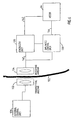
- Fig. 6 shows the basic parts of a remote control system of the device of the invention including the electric motor 44 of the embodiment shown in Fig. 3 .
- the remote control system is based on the transmission of electromagnetic wave signals, often of high frequencies in the order of 100 kHz - 1 gHz, through the skin 130 of the patient.
- all parts placed to the left of the skin 130 are located outside the patient's body and all parts placed to the right of the skin 130 are implanted. Any suitable remote control system may be used.
- An external signal transmitting antenna 132 is to be positioned close to a signal receiving antenna 134 implanted close to the skin 130.
- the receiving antenna 134 may be placed for example inside the abdomen of the patient.
- the receiving antenna 134 comprises a coil, approximately 1-100 mm, preferably 25 mm in diameter, wound with a very thin wire and tuned with a capacitor to a specific high frequency.
- a small coil is chosen if it is to be implanted under the skin of the patient and a large coil is chosen if it is to be implanted in the abdomen of the patient.
- the transmitting antenna 132 comprises a coil having about the same size as the coil of the receiving antenna 134 but wound with a thick wire that can handle the larger currents that is necessary.
- the coil of the transmitting antenna 132 is tuned to the same specific high frequency as the coil of the receiving antenna 134.
- An external control unit 136 comprises a microprocessor, a high frequency electromagnetic wave signal generator and a power amplifier.
- the microprocessor of the control unit 136 is adapted to switch the generator on/off and to modulate signals generated by the generator to send digital information via the power amplifier and the antennas 132,134 to an implanted control unit 138.
- digital signal codes are used.
- a conventional keypad placed on the external control unit 136 is connected to the microprocessor thereof. The keypad is used to order the microprocessor to send digital signals to either increase or decrease the size of the restriction opening defined by the loop of the restriction member 2.
- the microprocessor starts a command by applying a high frequency signal on the antenna 132.
- commands are sent to increase or decrease the size of said restriction opening of the restriction member 2 in predefined steps.
- the commands are sent as digital packets in the form illustrated below. Start pattern, 8 bits Command, 8 bits Count, 8 bits Checksum, 8 bits
- the commands are sent continuously during a rather long time period ( e.g . about 30 seconds or more).
- a new increase or decrease step is desired the Count byte is increased by one to allow the implanted control unit 138 to decode and understand that another step is demanded by the external control unit 136. If any part of the digital packet is erroneous, its content is simply ignored.
- an implanted energizer unit 126 draws energy from the high frequency electromagnetic wave signals received by the receiving antenna 134.
- the energizer unit 126 stores the energy in a power supply, such as a large capacitor, powers the control unit 138 and powers the electric motor' 44 via a line 142.
- the control unit 138 comprises a demodulator and a microprocessor.
- the demodulator demodulates digital signals sent from the external control unit 136.
- the microprocessor of the control unit 138 receives the digital packet, decodes it and, provided that the power supply of the energizer unit 126 has sufficient energy stored, sends a signal via a signal line 144 to the motor 44 to either increase or decrease the size of the restriction opening of the restriction member 2 depending on the received command code.
- the energy stored in the power supply of the energizer unit may only be used for powering a switch, and the energy for powering the motor 44 may be obtained from another implanted power source of relatively high capacity, for example a battery.
- the switch is adapted to connect said battery to the control unit 138 in an "on" mode when said switch is powered by said power supply and to keep said battery disconnected from the control unit in a "standby" mode when said switch is unpowered.
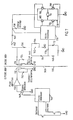
- the external control unit 136 comprises a microprocessor 146, a signal generator 148 and a power amplifier 150 connected thereto.
- the microprocessor 146 is adapted to switch the signal generator 148 on/off and to modulate signals generated by the signal generator 148 with digital commands that are sent to implanted components of the food intake restriction device.
- the power amplifier 150 amplifies the signals and sends them to the external signal transmitting antenna 132.
- the antenna 132 is connected in parallel with a capacitor 152 to form a resonant circuit tuned to the frequency generated by the signal generator 148.
- the implanted signal receiving antenna coil 134 forms together with a capacitor 154 a resonant circuit that is tuned to the same frequency as the transmitting antenna 132.
- the signal receiving antenna coil 134 induces a current from the received high frequency electromagnetic waves and a rectifying diode 160 rectifies the induced current, which charges a storage capacitor 158.
- a coil 156 connected between the antenna coil 134 and the diode 160 prevents the capacitor 158 and the diode 160 from loading the circuit of the signal receiving antenna 134 at higher frequencies.
- the coil 156 makes it possible to charge the capacitor 158 and to transmit digital information using amplitude modulation.
- a capacitor 162 and a resistor 164 connected in parallel and a diode 166 forms a detector used to detect amplitude modulated digital information.
- a filter circuit is formed by a resistor 168 connected in series with a resistor 170 connected in series with a capacitor 172 connected in series with the resistor 168 via ground, and a capacitor 174, one terminal of which is connected between the resistors 168,170 and the other terminal of which is connected between the diode 166 and the circuit formed by the capacitor 162 and resistor 164.
- the filter circuit is used to filter out undesired low and high frequencies.
- the detected and filtered signals are fed to an implanted microprocessor 176 that decodes the digital information and controls the motor 44 via an H-bridge 178 comprising transistors 180,182,184 and 186.
- the motor 44 can be driven in two opposite directions by the H-bridge 178.
- the microprocessor 176 also monitors the amount of stored energy in the storage capacitor 158. Before sending signals to activate the motor 44, the microprocessor 176 checks whether the energy stored in the storage capacitor 158 is enough. If the stored energy is not enough to perform the requested operation, the microprocessor 176 waits for the received signals to charge the storage capacitor 158 before activating the motor 44.
- control units may be replaced by discrete components.
- the power amplifier of the external control unit may be omitted if the signals generated by the signal generator are strong enough. Therefore, the invention is to be accorded the broadest interpretation of the appended claims to encompass all equivalent structures and assemblies.
- One further advantage with this invention is that there may be a night button on the remote control setting the adjustment means in a position with a larger stoma diameter during the night, thus avoiding vomiting or nausa.
Landscapes
- Health & Medical Sciences (AREA)
- Child & Adolescent Psychology (AREA)
- Obesity (AREA)
- Nursing (AREA)
- Orthopedic Medicine & Surgery (AREA)
- Engineering & Computer Science (AREA)
- Biomedical Technology (AREA)
- Heart & Thoracic Surgery (AREA)
- Vascular Medicine (AREA)
- Life Sciences & Earth Sciences (AREA)
- Animal Behavior & Ethology (AREA)
- General Health & Medical Sciences (AREA)
- Public Health (AREA)
- Veterinary Medicine (AREA)
- Prostheses (AREA)
- Surgical Instruments (AREA)
- Massaging Devices (AREA)
- Bakery Products And Manufacturing Methods Therefor (AREA)
- Means For Warming Up And Starting Carburetors (AREA)
Claims (23)
- Vorrichtung zur Begrenzung der Nahrungsaufnahme durch Ausgestalten einer Öffnung in den Magen oder der Speiseröhre eines Patienten, die Vorrichtung umfassend:ein ausgedehntes Beschränkungselement (2);Formgebungsmittel zum Ausbilden des ausgedehnten Beschränkungselementes in zumindest einer im Wesentlichen geschlossenen Schlinge um den Magen oder die Speiseröhre, wobei die Schlinge eine Beschränkungsöffnung (3) definiert;ein Einstellmittel (5) zum Einstellen des Beschränkungselementes der Schlinge, um die Größe der Beschränkungsöffnung zu ändern;implantierbare, hydraulische Funktionsmittel (6, 8, 10, 12, 10, 14, 76-86) zum Betreiben des Einstellmittels (5) in einer nicht-invasiven Art, undein implantierbares Reservoir (4, 10, 16), das eine vorbestimmte Menge einer hydraulischen Flüssigkeit enthält, wobei das hydraulische Funktionsmittel zum Betreiben des Einstellmittels unter Nutzung der hydraulischen Flüssigkeit aus dem Reservoir ausgebildet ist,wobei das Einstellmittel einen expandierbaren Hohlraum (5) in dem Beschränkungselement (2) aufweist, wobei die Größe der Einstellöffnung (3) durch eine Expansion des Hohlraumes reduziert wird und durch Kontraktion des Hohlraumes vergrößert wird, und das hydraulische Funktionsmittel (6, 8, 10, 12, 10, 14, 76-86) zum Verwenden der hydraulischen Flüssigkeit aus dem Reservoir (4, 10, 16) zum Expandieren des Hohlraumes ausgebildet ist, und ferner ausgebildet ist, um hydraulischen Flüssigkeit von dem Hohlraum in das Reservoir zu bringen, um den Hohlraum zu kontrahieren, um so die Größe der Beschränkungsöffnung zu steuern,wobei das hydraulische Funktionsmittel eine aktivierbare Pumpe (6, 12) zum Pumpen der Flüssigkeit zwischen dem Reservoir (4) und dem Hohlraum (5) des Beschränkungselementes (2) aufweist,und wobei die Pumpe ein erstes Aktivierungselement zum Aktivieren der Pumpe zum Pumpen von Flüssigkeit von dem Reservoir (4) zu dem Hohlraum (5) des Beschränkungselementes (2) aufweist und ein zweites Aktivierungselement zum Aktivieren der Pumpe aufweist, um Flüssigkeit von dem Hohlraum zu dem Reservoir zu pumpen, dadurch gekennzeichnet, dass:zumindest eines der Aktivierungselemente ausgebildet ist, um beim Vorliegen eines externen Druckes, der eine vorbestimmte Größe überschreitet, betriebsbereit zu sein.
- Vorrichtung nach Anspruch 1, wobei das erste und zweite Aktivierungselement durch eine manuelle Bedienung derselben betriebsbereit sind.
- Vorrichtung nach Anspruch 1, wobei zumindest eines von den ersten und zweiten Aktivierungselementen durch ein magnetisches Mittel, hydraulisches Mittel oder elektrisches Kontrollmittel betriebsbereit ist.
- Vorrichtung nach einem der Ansprüche 1 bis 3, weiter umfassend ein drahtloses Fernbedienungsmittel (44, 126, 132-144) zum nicht-invasiven Steuern der hydraulischen Funktionsmittel (6, 8; 10; 12; 10, 14; 76-86).
- Vorrichtung nach Anspruch 4, wobei das Fernbedienungsmittel (44, 126, 132-144) separate Signalsendemittel (132, 136) umfasst und implantierbare Signalempfangsmittel (134, 138) umfasst.
- Vorrichtung nach Anspruch 5, wobei das Signalempfangsmittel (134, 138) eine Kontrolleinheit (138) zum Kontrollieren der hydraulischen Funktionsmittel (6, 8, 10, 12, 10, 14, 76-86) in Antwort auf Signale, die von dem Signalsendemittel (132, 136) empfangen wurden, umfasst.
- Vorrichtung nach Anspruch 6, weiter umfassend eine implantierbare Energieversorgungseinheit (136) zum Bereitstellen von Energie für Energie-verbrauchende Komponenten der Vorrichtung, die in dem Patienten implantiert sind.
- Vorrichtung nach Anspruch 7, weiter umfassend einen implantierbaren Motor (44) zum Betreiben der hydraulischen Funktionsmittel (6, 8, 10, 12, 10, 14, 76-86).
- Vorrichtung nach Anspruch 8, wobei die Kontrolleinheit (138) ausgebildet ist, um den Motor (44) mit Energie, die von der Energieversorgungseinheit (136) in Antwort auf Signale, die von dem Signalsendemittel (132, 136) empfangen wurden, zu betreiben.
- Vorrichtung nach Anspruch 7, wobei die Energieversorgungseinheit (126) ausgebildet ist, um Energie von den Signalen, wie sie zu dem Signalempfangsmittel (134, 138) übertragen werden, in elektrische Energie umzuwandeln.
- Vorrichtung nach einem der vorhergehenden Ansprüche, wobei das Formgebungsmittel ausgebildet ist, um das Beschränkungsmittel (2) als eine Schlinge, die eine vorbestimmte Größe hat, zu formen.
- Vorrichtung nach Anspruch 4, wobei das Fernbedienungsmittel (44, 126, 132-144) Mittel zur drahtlosen Übertragung von Energie von außerhalb des Patientenkörpers zu den Energie-verbrauchenden implantieren Komponenten der Vorrichtung aufweist.
- Vorrichtung nach Anspruch 12, weiter umfassend einen implantierbaren Motor (44) zum Betreiben der hydraulischen Funktionsmittel (6, 8, 10, 12, 10, 14, 76-86), wobei das Mittel der drahtlosen Übertragung von Energie ausgebildet ist, um direkt den Motor mit der übertragenen Energie zu versorgen.
- Vorrichtung nach Anspruch 13, wobei die Energie, die durch das Mittel der Energieübertragung übertragen wurde, ein Wellensignal umfasst.
- Vorrichtung nach Anspruch 13, wobei die Energie, die durch das Mittel zur Energieübertragung übertragen wurde, ein elektrisches Feld oder ein magnetisches Feld aufweist.
- Vorrichtung nach Anspruch 1, wobei das Einstellmittel (5) ausgebildet ist, um die Größe der Beschränkungsöffnung (3) zu ändern, so dass die äußere eingeschlossene Umfangsfläche des Beschränkungsmittels (2) sich ändert.
- Vorrichtung nach Anspruch 1, wobei das Einstellmittel (5) ausgebildet ist, um die Größe der Beschränkungsöffnung (3) zu ändern, so dass die äußere eingeschlossene Umfangsfläche des Beschränkungsmittels (2) sich nicht ändert.
- Vorrichtung nach Anspruch 5, wobei das Signalsendemittel (132, 136) und das Signalempfangsmittel (134, 138) zum Senden und zum Empfangen von Signalen in Form von digitalen Impulsen ausgebildet sind.
- Vorrichtung nach Anspruch 18, wobei die digitalen Impulse ein magnetisches oder ein elektrisches Feld aufweisen.
- Vorrichtung nach einem der Ansprüche 5 und 6, wobei das Signalsendemittel (132, 136) und das Signalempfangsmittel (134, 138) zum Senden und zum Empfangen von Wellensignalen ausgebildet sind.
- Vorrichtung nach Anspruch 20, wobei die Wellensignale elektromagnetische Wellen, Schallwellen oder Trägerwellen des Fernbedienungssignales aufweisen.
- Vorrichtung nach einem der Ansprüche 7, 10, 12-15, wobei die Energieversorgungseinheit (136) ausgebildet ist, um die Energie von den Signalen in Gleich- oder Wechselstrom zu transferieren.
- Vorrichtung nach Anspruch 4, wobei das Fernbedienungsmittel (44, 126, 132-144) ausgebildet ist, um Informationen über die Größe der Beschränkungsöffnung (3) zu erhalten, und um das Einstellmittel (5) zum Einstellen des Beschränkungsmittels (2) in Antwort auf den Erhalt der Informationen anzuweisen.
Priority Applications (1)
| Application Number | Priority Date | Filing Date | Title |
|---|---|---|---|
| EP10179739.7A EP2295010B1 (de) | 1998-08-13 | 1999-08-12 | Vorrichtung zur Begrenzung der Nahrungsaufnahme |
Applications Claiming Priority (3)
| Application Number | Priority Date | Filing Date | Title |
|---|---|---|---|
| US133322 | 1998-08-13 | ||
| US09/133,322 US6460543B1 (en) | 1998-08-13 | 1998-08-13 | Non-injection port food intake restriction device |
| EP99943572A EP1105075B1 (de) | 1998-08-13 | 1999-08-12 | Vorrichtung zur begrenzung der nahrungsaufnahme |
Related Parent Applications (2)
| Application Number | Title | Priority Date | Filing Date |
|---|---|---|---|
| EP99943572A Division EP1105075B1 (de) | 1998-08-13 | 1999-08-12 | Vorrichtung zur begrenzung der nahrungsaufnahme |
| EP99943572.0 Division | 1999-08-12 |
Related Child Applications (2)
| Application Number | Title | Priority Date | Filing Date |
|---|---|---|---|
| EP10179739.7A Division EP2295010B1 (de) | 1998-08-13 | 1999-08-12 | Vorrichtung zur Begrenzung der Nahrungsaufnahme |
| EP10179739.7 Division-Into | 2010-09-25 |
Publications (2)
| Publication Number | Publication Date |
|---|---|
| EP1554997A1 EP1554997A1 (de) | 2005-07-20 |
| EP1554997B1 true EP1554997B1 (de) | 2010-11-24 |
Family
ID=22458042
Family Applications (3)
| Application Number | Title | Priority Date | Filing Date |
|---|---|---|---|
| EP05075918A Expired - Lifetime EP1554997B1 (de) | 1998-08-13 | 1999-08-12 | Vorrichtung zur Begrenzung der Nahrungsaufnahme |
| EP10179739.7A Expired - Lifetime EP2295010B1 (de) | 1998-08-13 | 1999-08-12 | Vorrichtung zur Begrenzung der Nahrungsaufnahme |
| EP99943572A Expired - Lifetime EP1105075B1 (de) | 1998-08-13 | 1999-08-12 | Vorrichtung zur begrenzung der nahrungsaufnahme |
Family Applications After (2)
| Application Number | Title | Priority Date | Filing Date |
|---|---|---|---|
| EP10179739.7A Expired - Lifetime EP2295010B1 (de) | 1998-08-13 | 1999-08-12 | Vorrichtung zur Begrenzung der Nahrungsaufnahme |
| EP99943572A Expired - Lifetime EP1105075B1 (de) | 1998-08-13 | 1999-08-12 | Vorrichtung zur begrenzung der nahrungsaufnahme |
Country Status (11)
| Country | Link |
|---|---|
| US (2) | US6460543B1 (de) |
| EP (3) | EP1554997B1 (de) |
| AT (2) | ATE293415T1 (de) |
| AU (1) | AU746371B2 (de) |
| BR (1) | BR9912794A (de) |
| CA (1) | CA2338359C (de) |
| DE (2) | DE69942986D1 (de) |
| DK (1) | DK1105075T3 (de) |
| ES (1) | ES2239458T3 (de) |
| MX (1) | MXPA01000598A (de) |
| WO (1) | WO2000009049A1 (de) |
Families Citing this family (190)
| Publication number | Priority date | Publication date | Assignee | Title |
|---|---|---|---|---|
| US20050192629A1 (en) * | 1999-06-25 | 2005-09-01 | Usgi Medical Inc. | Methods and apparatus for creating and regulating a gastric stoma |
| US6461292B1 (en) | 1999-08-12 | 2002-10-08 | Obtech Medical Ag | Anal incontinence treatment with wireless energy supply |
| US6464628B1 (en) * | 1999-08-12 | 2002-10-15 | Obtech Medical Ag | Mechanical anal incontinence |
| US6482145B1 (en) | 2000-02-14 | 2002-11-19 | Obtech Medical Ag | Hydraulic anal incontinence treatment |
| US6471635B1 (en) | 2000-02-10 | 2002-10-29 | Obtech Medical Ag | Anal incontinence disease treatment with controlled wireless energy supply |
| MXPA02007654A (es) * | 2000-02-10 | 2004-08-23 | Potencia Medical Ag | Aparato mecanico para el tratamiento de impotencia. |
| EP1253880B1 (de) | 2000-02-10 | 2005-09-14 | Potencia Medical AG | Kontrollierte harninkontinenzbehandlung |
| DE60113965T2 (de) | 2000-02-10 | 2006-07-06 | Potencia Medical Ag | Behandlung der harninkontinenz mit kabelloser energiezufuhr |
| DE60131726T2 (de) | 2000-02-11 | 2008-11-06 | Potencia Medical Ag | Kontrollierte impotenzbehandlung |
| CN101138528B (zh) | 2000-02-11 | 2015-02-25 | 波坦蒂卡股份公司 | 带能量变换装置的阳萎治疗设备 |
| ATE324087T1 (de) | 2000-02-14 | 2006-05-15 | Potencia Medical Ag | Männliche impotentzprothesevorrichtung mit drahtloser energieversorgung |
| ATE296071T1 (de) | 2000-02-14 | 2005-06-15 | Potencia Medical Ag | Penisprothese |
| US6475136B1 (en) * | 2000-02-14 | 2002-11-05 | Obtech Medical Ag | Hydraulic heartburn and reflux treatment |
| US20030100929A1 (en) | 2000-02-14 | 2003-05-29 | Peter Forsell | Controlled penile prosthesis |
| FR2813786B1 (fr) | 2000-09-11 | 2003-03-14 | Medical Innovation Dev | Procede et dispositif de commande du gonflement d'une enveloppe prothetique gonflable et prothese en faisant application |
| US7033373B2 (en) | 2000-11-03 | 2006-04-25 | Satiety, Inc. | Method and device for use in minimally invasive placement of space-occupying intragastric devices |
| US6558400B2 (en) | 2001-05-30 | 2003-05-06 | Satiety, Inc. | Obesity treatment tools and methods |
| US7083629B2 (en) | 2001-05-30 | 2006-08-01 | Satiety, Inc. | Overtube apparatus for insertion into a body |
| US6845776B2 (en) | 2001-08-27 | 2005-01-25 | Richard S. Stack | Satiation devices and methods |
| US6675809B2 (en) | 2001-08-27 | 2004-01-13 | Richard S. Stack | Satiation devices and methods |
| US7097665B2 (en) | 2003-01-16 | 2006-08-29 | Synecor, Llc | Positioning tools and methods for implanting medical devices |
| CN101810521B (zh) | 2001-08-27 | 2015-05-13 | 辛尼科有限责任公司 | 饱满装置和方法 |
| US7146984B2 (en) | 2002-04-08 | 2006-12-12 | Synecor, Llc | Method and apparatus for modifying the exit orifice of a satiation pouch |
| US7294120B1 (en) * | 2002-04-18 | 2007-11-13 | Haleys Pump Company | Automated instillation apparatus and method |
| AU2003239060A1 (en) | 2002-07-29 | 2004-02-16 | Potencia Medical Ag | Durable implant |
| US20040034275A1 (en) | 2002-07-29 | 2004-02-19 | Peter Forsell | Multi-material incontinence treatment constriction device |
| US6746460B2 (en) | 2002-08-07 | 2004-06-08 | Satiety, Inc. | Intra-gastric fastening devices |
| US7338433B2 (en) | 2002-08-13 | 2008-03-04 | Allergan, Inc. | Remotely adjustable gastric banding method |
| ES2617452T3 (es) * | 2002-08-28 | 2017-06-19 | Apollo Endosurgery, Inc | Dispositivo de banda gástrica resistente a la fatiga |
| US7033384B2 (en) | 2002-08-30 | 2006-04-25 | Satiety, Inc. | Stented anchoring of gastric space-occupying devices |
| US7214233B2 (en) | 2002-08-30 | 2007-05-08 | Satiety, Inc. | Methods and devices for maintaining a space occupying device in a relatively fixed location within a stomach |
| US7901419B2 (en) * | 2002-09-04 | 2011-03-08 | Allergan, Inc. | Telemetrically controlled band for regulating functioning of a body organ or duct, and methods of making, implantation and use |
| US7220237B2 (en) | 2002-10-23 | 2007-05-22 | Satiety, Inc. | Method and device for use in endoscopic organ procedures |
| US7229428B2 (en) | 2002-10-23 | 2007-06-12 | Satiety, Inc. | Method and device for use in endoscopic organ procedures |
| US6656194B1 (en) | 2002-11-05 | 2003-12-02 | Satiety, Inc. | Magnetic anchoring devices |
| US20040143342A1 (en) | 2003-01-16 | 2004-07-22 | Stack Richard S. | Satiation pouches and methods of use |
| US7175638B2 (en) | 2003-04-16 | 2007-02-13 | Satiety, Inc. | Method and devices for modifying the function of a body organ |
| AT412525B (de) * | 2003-07-25 | 2005-04-25 | Wolfgang Dr Lechner | Steuerbares magenband |
| CA2532872C (en) * | 2003-07-25 | 2012-10-30 | Wolfgang Lechner | Adjustable stomach band |
| US8206456B2 (en) | 2003-10-10 | 2012-06-26 | Barosense, Inc. | Restrictive and/or obstructive implant system for inducing weight loss |
| US20050247320A1 (en) | 2003-10-10 | 2005-11-10 | Stack Richard S | Devices and methods for retaining a gastro-esophageal implant |
| US7097650B2 (en) | 2003-10-14 | 2006-08-29 | Satiety, Inc. | System for tissue approximation and fixation |
| US7914543B2 (en) | 2003-10-14 | 2011-03-29 | Satiety, Inc. | Single fold device for tissue fixation |
| AU2004235622A1 (en) * | 2003-12-17 | 2005-07-07 | Ethicon Endo-Surgery, Inc. | Mechanically adjustable gastric band |
| BRPI0507075B1 (pt) | 2004-01-23 | 2016-02-23 | Allergan Inc | faixa gástrica ajustável de peça única fixável desprendidamente |
| US20050177176A1 (en) | 2004-02-05 | 2005-08-11 | Craig Gerbi | Single-fold system for tissue approximation and fixation |
| CA2556228C (en) | 2004-02-13 | 2014-05-13 | Satiety, Inc. | Methods for reducing hollow organ volume |
| AU2005218318A1 (en) | 2004-02-27 | 2005-09-15 | Ethicon Endo-Surgery, Inc | Methods and devices for reducing hollow organ volume |
| WO2005087147A1 (en) | 2004-03-08 | 2005-09-22 | Endoart S.A. | Closure system for tubular organs |
| US8628547B2 (en) | 2004-03-09 | 2014-01-14 | Ethicon Endo-Surgery, Inc. | Devices and methods for placement of partitions within a hollow body organ |
| US9028511B2 (en) | 2004-03-09 | 2015-05-12 | Ethicon Endo-Surgery, Inc. | Devices and methods for placement of partitions within a hollow body organ |
| US8252009B2 (en) | 2004-03-09 | 2012-08-28 | Ethicon Endo-Surgery, Inc. | Devices and methods for placement of partitions within a hollow body organ |
| US8449560B2 (en) | 2004-03-09 | 2013-05-28 | Satiety, Inc. | Devices and methods for placement of partitions within a hollow body organ |
| AU2004317849B2 (en) | 2004-03-18 | 2011-03-31 | Allergan, Inc. | Apparatus and method for volume adjustment of intragastric balloons |
| EP1750627B1 (de) | 2004-03-26 | 2018-10-10 | Ethicon Endo-Surgery, Inc. | Systeme zur behandlung von fettsucht |
| FR2869218B1 (fr) * | 2004-04-21 | 2006-06-09 | Europlak Sa | Dispositif de cerclage gastrique ou "anneau gastrique" motorise comportant au moins une antenne de reception desorientee pour l'alimentation, la commande a distance et l'envoi de donnees, par induction |
| US7717843B2 (en) * | 2004-04-26 | 2010-05-18 | Barosense, Inc. | Restrictive and/or obstructive implant for inducing weight loss |
| WO2005120363A1 (en) | 2004-06-03 | 2005-12-22 | Mayo Foundation For Medical Education And Research | Obesity treatment and device |
| US7955357B2 (en) | 2004-07-02 | 2011-06-07 | Ellipse Technologies, Inc. | Expandable rod system to treat scoliosis and method of using the same |
| AU2005301058A1 (en) * | 2004-11-05 | 2006-05-11 | Electronic Dietary Foods Inc. | Controlled degradation of expandable polymers in gastric volume reduction treatment |
| US20060106288A1 (en) | 2004-11-17 | 2006-05-18 | Roth Alex T | Remote tissue retraction device |
| US7775966B2 (en) * | 2005-02-24 | 2010-08-17 | Ethicon Endo-Surgery, Inc. | Non-invasive pressure measurement in a fluid adjustable restrictive device |
| US20080051822A1 (en) * | 2005-01-18 | 2008-02-28 | Widgerow Alan D | Methods and apparatus for use in medical treatment |
| US20060252983A1 (en) * | 2005-02-11 | 2006-11-09 | Lembo Nicholas J | Dynamically adjustable gastric implants and methods of treating obesity using dynamically adjustable gastric implants |
| US7775215B2 (en) * | 2005-02-24 | 2010-08-17 | Ethicon Endo-Surgery, Inc. | System and method for determining implanted device positioning and obtaining pressure data |
| US7699770B2 (en) | 2005-02-24 | 2010-04-20 | Ethicon Endo-Surgery, Inc. | Device for non-invasive measurement of fluid pressure in an adjustable restriction device |
| US8066629B2 (en) | 2005-02-24 | 2011-11-29 | Ethicon Endo-Surgery, Inc. | Apparatus for adjustment and sensing of gastric band pressure |
| US7658196B2 (en) | 2005-02-24 | 2010-02-09 | Ethicon Endo-Surgery, Inc. | System and method for determining implanted device orientation |
| US8016744B2 (en) | 2005-02-24 | 2011-09-13 | Ethicon Endo-Surgery, Inc. | External pressure-based gastric band adjustment system and method |
| US7909754B2 (en) * | 2005-02-24 | 2011-03-22 | Ethicon Endo-Surgery, Inc. | Non-invasive measurement of fluid pressure in an adjustable gastric band |
| US7927270B2 (en) | 2005-02-24 | 2011-04-19 | Ethicon Endo-Surgery, Inc. | External mechanical pressure sensor for gastric band pressure measurements |
| US20060276812A1 (en) * | 2005-04-04 | 2006-12-07 | Hill James W | Dynamic reinforcement of the lower esophageal sphincter |
| US8251888B2 (en) | 2005-04-13 | 2012-08-28 | Mitchell Steven Roslin | Artificial gastric valve |
| US20060244291A1 (en) * | 2005-04-29 | 2006-11-02 | Buell Motorcycle Company | Movable tailrack for a motorcycle |
| US7666180B2 (en) | 2005-05-20 | 2010-02-23 | Tyco Healthcare Group Lp | Gastric restrictor assembly and method of use |
| US7691053B2 (en) | 2005-05-20 | 2010-04-06 | Tyco Healthcare Group Lp | Gastric restrictor assembly and method of use |
| CA2611477C (en) | 2005-06-10 | 2012-01-17 | Wilson-Cook Medical, Inc. | Cautery catheter |
| US8298133B2 (en) * | 2005-07-15 | 2012-10-30 | Ethicon Endo-Surgery, Inc. | Gastric band composed of different hardness materials |
| US8182411B2 (en) * | 2005-07-15 | 2012-05-22 | Ethicon Endo-Surgery, Inc. | Gastric band with mating end profiles |
| US7618365B2 (en) * | 2005-07-15 | 2009-11-17 | Ethicon Endo-Surgery, Inc. | Method of implating a medical device using a suture tab extender |
| US7364542B2 (en) * | 2005-07-15 | 2008-04-29 | Ethicon Endo-Surgery, Inc. | Gastric band suture tab extender |
| US7416528B2 (en) | 2005-07-15 | 2008-08-26 | Ethicon Endo-Surgery, Inc. | Latching device for gastric band |
| US20070015955A1 (en) * | 2005-07-15 | 2007-01-18 | Mark Tsonton | Accordion-like gastric band |
| US7615001B2 (en) * | 2005-07-15 | 2009-11-10 | Ethicon Endo-Surgery, Inc. | Precurved gastric band |
| US7367937B2 (en) * | 2005-07-15 | 2008-05-06 | Ethicon Endo-Surgey, Inc. | Gastric band |
| US9055942B2 (en) | 2005-10-03 | 2015-06-16 | Boston Scienctific Scimed, Inc. | Endoscopic plication devices and methods |
| AU2006330911B2 (en) | 2005-12-22 | 2012-10-04 | Cook Medical Technologies Llc | Intragastric bag for treating obesity |
| US8043206B2 (en) | 2006-01-04 | 2011-10-25 | Allergan, Inc. | Self-regulating gastric band with pressure data processing |
| US7798954B2 (en) | 2006-01-04 | 2010-09-21 | Allergan, Inc. | Hydraulic gastric band with collapsible reservoir |
| US20070198039A1 (en) * | 2006-01-27 | 2007-08-23 | Wilson-Cook Medical, Inc. | Intragastric device for treating obesity |
| US7908700B2 (en) * | 2006-02-28 | 2011-03-22 | Dipippo Joe J | Self-cleaning hair brush |
| WO2007104356A1 (de) | 2006-03-13 | 2007-09-20 | Rudolf Steffen | Adaptive einrichtung und adaptives verfahren zur anpassung der magenöffnung eines patienten |
| US9579227B2 (en) | 2006-03-29 | 2017-02-28 | Eat Little Inc. | Ingestible implement for weight control |
| MX2008012587A (es) * | 2006-03-29 | 2009-01-14 | Electronic Dietary Foods Inc | Implemento ingerible para control de peso. |
| US8152710B2 (en) | 2006-04-06 | 2012-04-10 | Ethicon Endo-Surgery, Inc. | Physiological parameter analysis for an implantable restriction device and a data logger |
| US8342183B2 (en) * | 2006-04-19 | 2013-01-01 | Vibrynt, Inc. | Devices and methods for treatment of obesity |
| US20070255336A1 (en) * | 2006-04-28 | 2007-11-01 | Medtronic, Inc. | Gastric constriction device with selectable electrode combinations |
| US20070255335A1 (en) * | 2006-04-28 | 2007-11-01 | Medtronic, Inc. | Controller for gastric constriction device with selectable electrode configurations |
| US7763039B2 (en) * | 2006-06-09 | 2010-07-27 | Ethicon Endo-Surgery, Inc. | Articulating blunt dissector/gastric band application device |
| US8109895B2 (en) | 2006-09-02 | 2012-02-07 | Barosense, Inc. | Intestinal sleeves and associated deployment systems and methods |
| US9314361B2 (en) | 2006-09-15 | 2016-04-19 | Boston Scientific Scimed, Inc. | System and method for anchoring stomach implant |
| US20080319435A1 (en) * | 2006-10-12 | 2008-12-25 | Boston Scientific Scimed, Inc. | Shape-changing tissue constrictor and methods of use |
| US8246533B2 (en) | 2006-10-20 | 2012-08-21 | Ellipse Technologies, Inc. | Implant system with resonant-driven actuator |
| US7862502B2 (en) | 2006-10-20 | 2011-01-04 | Ellipse Technologies, Inc. | Method and apparatus for adjusting a gastrointestinal restriction device |
| US8417329B2 (en) * | 2007-05-09 | 2013-04-09 | Metacure Ltd. | Analysis and regulation of food intake |
| US8007507B2 (en) | 2007-05-10 | 2011-08-30 | Cook Medical Technologies Llc | Intragastric bag apparatus and method of delivery for treating obesity |
| US8435203B2 (en) | 2007-06-20 | 2013-05-07 | Covidien Lp | Gastric restrictor assembly and method of use |
| US20090012542A1 (en) * | 2007-07-03 | 2009-01-08 | Synecor, Llc | Satiation devices and methods for controlling obesity |
| CA2696993C (en) | 2007-07-18 | 2017-01-03 | Samuel T. Crews | Endoscopic implant system and method |
| WO2009011881A1 (en) | 2007-07-18 | 2009-01-22 | Barosense, Inc. | Overtube introducer for use in endoscopic bariatric surgery |
| SI2211768T1 (sl) | 2007-10-11 | 2021-11-30 | Implantica Patent Ltd. | Naprava za krmiljenje toka v telesnem organu |
| US8992409B2 (en) | 2007-10-11 | 2015-03-31 | Peter Forsell | Method for controlling flow in a bodily organ |
| US8795153B2 (en) | 2007-10-11 | 2014-08-05 | Peter Forsell | Method for treating female sexual dysfunction |
| US8696543B2 (en) | 2007-10-11 | 2014-04-15 | Kirk Promotion Ltd. | Method for controlling flow of intestinal contents in a patient's intestines |
| US8057472B2 (en) | 2007-10-30 | 2011-11-15 | Ellipse Technologies, Inc. | Skeletal manipulation method |
| US7883524B2 (en) | 2007-12-21 | 2011-02-08 | Wilson-Cook Medical Inc. | Method of delivering an intragastric device for treating obesity |
| US8016851B2 (en) | 2007-12-27 | 2011-09-13 | Cook Medical Technologies Llc | Delivery system and method of delivery for treating obesity |
| US20090171383A1 (en) | 2007-12-31 | 2009-07-02 | David Cole | Gastric space occupier systems and methods of use |
| EP2244759B1 (de) * | 2008-01-28 | 2024-11-27 | Implantica Patent Ltd. | Filterreinigungsvorrichtung |
| ES2981249T3 (es) | 2008-01-29 | 2024-10-08 | Implantica Patent Ltd | Un dispositivo para el tratamiento de la obesidad |
| US20090209995A1 (en) * | 2008-02-14 | 2009-08-20 | Byrum Randal T | Implantable adjustable sphincter system |
| US8034065B2 (en) * | 2008-02-26 | 2011-10-11 | Ethicon Endo-Surgery, Inc. | Controlling pressure in adjustable restriction devices |
| US8020741B2 (en) | 2008-03-18 | 2011-09-20 | Barosense, Inc. | Endoscopic stapling devices and methods |
| US20090248148A1 (en) | 2008-03-25 | 2009-10-01 | Ellipse Technologies, Inc. | Systems and methods for adjusting an annuloplasty ring with an integrated magnetic drive |
| US11202707B2 (en) | 2008-03-25 | 2021-12-21 | Nuvasive Specialized Orthopedics, Inc. | Adjustable implant system |
| WO2009132461A1 (en) * | 2008-04-28 | 2009-11-05 | Electronic Dietary Foods Inc. | Bezoar-forming units for weight control |
| US8423130B2 (en) | 2008-05-09 | 2013-04-16 | Metacure Limited | Optimization of thresholds for eating detection |
| US8292800B2 (en) | 2008-06-11 | 2012-10-23 | Allergan, Inc. | Implantable pump system |
| EP2362762A1 (de) | 2008-10-06 | 2011-09-07 | Allergan Medical Sàrl | Mechanisches magenband mit polstern |
| ES2985873T3 (es) | 2008-10-10 | 2024-11-07 | Implantica Patent Ltd | Medios de fijación para conjunto de control médico implantable |
| EP2349096B1 (de) | 2008-10-10 | 2021-01-27 | MedicalTree Patent Ltd. | Verbesserte künstliche herzklappe |
| AU2009302945C1 (en) | 2008-10-10 | 2016-04-21 | Medicaltree Patent Ltd | Heart help device, system, and method |
| US20210378811A1 (en) * | 2008-10-10 | 2021-12-09 | Peter Forsell | Fastening means for implantable medical control assembly |
| US9072907B2 (en) | 2008-10-10 | 2015-07-07 | Peter Forsell | Heart help device, system, and method |
| EP3120896A1 (de) | 2008-10-10 | 2017-01-25 | Kirk Promotion LTD. | System, vorrichtung und verfahren zur behandlung einer patientin mit sexueller dysfunktion |
| EP2349170B1 (de) | 2008-10-10 | 2023-09-27 | Implantica Patent Ltd. | Vorrichtung zur behandlung von weiblicher sexueller dysfunktion |
| US20100185049A1 (en) * | 2008-10-22 | 2010-07-22 | Allergan, Inc. | Dome and screw valves for remotely adjustable gastric banding systems |
| US8372093B2 (en) * | 2008-11-04 | 2013-02-12 | Koletry Processing L.L.C. | Systems and processes for controlling gastric bands based on geographic location |
| US8382756B2 (en) | 2008-11-10 | 2013-02-26 | Ellipse Technologies, Inc. | External adjustment device for distraction device |
| US7934631B2 (en) | 2008-11-10 | 2011-05-03 | Barosense, Inc. | Multi-fire stapling systems and methods for delivering arrays of staples |
| US8197490B2 (en) | 2009-02-23 | 2012-06-12 | Ellipse Technologies, Inc. | Non-invasive adjustable distraction system |
| US9622792B2 (en) | 2009-04-29 | 2017-04-18 | Nuvasive Specialized Orthopedics, Inc. | Interspinous process device and method |
| US20110184229A1 (en) * | 2009-05-01 | 2011-07-28 | Allergan, Inc. | Laparoscopic gastric band with active agents |
| EP2424583A2 (de) * | 2009-05-01 | 2012-03-07 | Allergan, Inc. | Laparoskopisches magenband mit wirkstoffen |
| US8961539B2 (en) | 2009-05-04 | 2015-02-24 | Boston Scientific Scimed, Inc. | Endoscopic implant system and method |
| US9949812B2 (en) | 2009-07-17 | 2018-04-24 | Peter Forsell | Vaginal operation method for the treatment of anal incontinence in women |
| US10952836B2 (en) | 2009-07-17 | 2021-03-23 | Peter Forsell | Vaginal operation method for the treatment of urinary incontinence in women |
| US20110137112A1 (en) * | 2009-08-28 | 2011-06-09 | Allergan, Inc. | Gastric band with electric stimulation |
| WO2011031400A2 (en) * | 2009-08-28 | 2011-03-17 | Allergan, Inc. | Gastric band with electric stimulation |
| US8678993B2 (en) | 2010-02-12 | 2014-03-25 | Apollo Endosurgery, Inc. | Remotely adjustable gastric banding system |
| US8758221B2 (en) | 2010-02-24 | 2014-06-24 | Apollo Endosurgery, Inc. | Source reservoir with potential energy for remotely adjustable gastric banding system |
| US8764624B2 (en) * | 2010-02-25 | 2014-07-01 | Apollo Endosurgery, Inc. | Inductively powered remotely adjustable gastric banding system |
| US8840541B2 (en) | 2010-02-25 | 2014-09-23 | Apollo Endosurgery, Inc. | Pressure sensing gastric banding system |
| DE102010011940B4 (de) * | 2010-03-18 | 2018-02-01 | Deutsches Zentrum für Luft- und Raumfahrt e.V. | Vorrichtung zur Energieversorgung von hydraulisch oder pneumatisch aktuierten aktiven Implantaten |
| US9028394B2 (en) | 2010-04-29 | 2015-05-12 | Apollo Endosurgery, Inc. | Self-adjusting mechanical gastric band |
| US20110270024A1 (en) | 2010-04-29 | 2011-11-03 | Allergan, Inc. | Self-adjusting gastric band having various compliant components |
| US9044298B2 (en) | 2010-04-29 | 2015-06-02 | Apollo Endosurgery, Inc. | Self-adjusting gastric band |
| US20110270025A1 (en) | 2010-04-30 | 2011-11-03 | Allergan, Inc. | Remotely powered remotely adjustable gastric band system |
| US8594806B2 (en) | 2010-04-30 | 2013-11-26 | Cyberonics, Inc. | Recharging and communication lead for an implantable device |
| WO2011146853A2 (en) | 2010-05-21 | 2011-11-24 | Barosense, Inc. | Tissue-acquisition and fastening devices and methods |
| CA2800255C (en) | 2010-05-27 | 2018-07-10 | The Regents Of The University Of Michigan | Device system for gastric volume reduction to facilitate weight loss |
| US9226840B2 (en) | 2010-06-03 | 2016-01-05 | Apollo Endosurgery, Inc. | Magnetically coupled implantable pump system and method |
| US8517915B2 (en) * | 2010-06-10 | 2013-08-27 | Allergan, Inc. | Remotely adjustable gastric banding system |
| US9248043B2 (en) | 2010-06-30 | 2016-02-02 | Ellipse Technologies, Inc. | External adjustment device for distraction device |
| US8734488B2 (en) | 2010-08-09 | 2014-05-27 | Ellipse Technologies, Inc. | Maintenance feature in magnetic implant |
| US8698373B2 (en) | 2010-08-18 | 2014-04-15 | Apollo Endosurgery, Inc. | Pare piezo power with energy recovery |
| US9211207B2 (en) | 2010-08-18 | 2015-12-15 | Apollo Endosurgery, Inc. | Power regulated implant |
| US20120059216A1 (en) | 2010-09-07 | 2012-03-08 | Allergan, Inc. | Remotely adjustable gastric banding system |
| US8961393B2 (en) | 2010-11-15 | 2015-02-24 | Apollo Endosurgery, Inc. | Gastric band devices and drive systems |
| US8852187B2 (en) | 2011-02-14 | 2014-10-07 | Ellipse Technologies, Inc. | Variable length device and method |
| US10743794B2 (en) | 2011-10-04 | 2020-08-18 | Nuvasive Specialized Orthopedics, Inc. | Devices and methods for non-invasive implant length sensing |
| WO2013066946A1 (en) | 2011-11-01 | 2013-05-10 | Ellipse Technologies, Inc. | Adjustable magnetic devices and methods of using same |
| US8876694B2 (en) | 2011-12-07 | 2014-11-04 | Apollo Endosurgery, Inc. | Tube connector with a guiding tip |
| US8961394B2 (en) | 2011-12-20 | 2015-02-24 | Apollo Endosurgery, Inc. | Self-sealing fluid joint for use with a gastric band |
| US9314362B2 (en) | 2012-01-08 | 2016-04-19 | Vibrynt, Inc. | Methods, instruments and devices for extragastric reduction of stomach volume |
| US8382775B1 (en) | 2012-01-08 | 2013-02-26 | Vibrynt, Inc. | Methods, instruments and devices for extragastric reduction of stomach volume |
| US9343923B2 (en) | 2012-08-23 | 2016-05-17 | Cyberonics, Inc. | Implantable medical device with backscatter signal based communication |
| US9935498B2 (en) | 2012-09-25 | 2018-04-03 | Cyberonics, Inc. | Communication efficiency with an implantable medical device using a circulator and a backscatter signal |
| EP3760147B1 (de) | 2012-10-29 | 2022-11-30 | NuVasive Specialized Orthopedics, Inc. | Einstellbare vorrichtungen zur behandlung von arthritis des kniegelenks |
| EP3903727A1 (de) * | 2013-03-15 | 2021-11-03 | Implantica Patent Ltd. | Einschränkungsvorrichtung |
| US10751094B2 (en) | 2013-10-10 | 2020-08-25 | Nuvasive Specialized Orthopedics, Inc. | Adjustable spinal implant |
| WO2015134747A1 (en) | 2014-03-06 | 2015-09-11 | Mayo Foundation For Medical Education And Research | Apparatus and methods of inducing weight loss using blood flow control |
| AU2015253313B9 (en) | 2014-04-28 | 2020-09-10 | Nuvasive Specialized Orthopedics, Inc. | System for informational magnetic feedback in adjustable implants |
| EP3236867B1 (de) | 2014-12-26 | 2022-02-23 | NuVasive Specialized Orthopedics, Inc. | Distraktionssysteme |
| US10238427B2 (en) | 2015-02-19 | 2019-03-26 | Nuvasive Specialized Orthopedics, Inc. | Systems and methods for vertebral adjustment |
| EP3361960B1 (de) | 2015-10-16 | 2023-05-10 | NuVasive Specialized Orthopedics, Inc. | Einstellbare vorrichtungen zur behandlung von arthritis des kniegelenks |
| CN108601611B (zh) | 2015-12-10 | 2021-11-02 | 诺威适骨科专科公司 | 用于牵张装置的外部调节装置 |
| CN108882953B (zh) | 2016-01-28 | 2021-09-03 | 诺威适骨科专科公司 | 骨搬移用的系统 |
| MX387449B (es) * | 2016-01-29 | 2025-03-18 | Ponce Carlos Eduardo Alvarez | Valvula intestinal tipo esfinter. |
| CA3009455A1 (en) | 2016-01-29 | 2017-08-03 | Carlos Eduardo Alvarez Ponce | Sphincter-type intestinal valve |
Family Cites Families (11)
| Publication number | Priority date | Publication date | Assignee | Title |
|---|---|---|---|---|
| US3750194A (en) * | 1971-03-16 | 1973-08-07 | Fairchild Industries | Apparatus and method for reversibly closing a natural or implanted body passage |
| IL67773A (en) | 1983-01-28 | 1985-02-28 | Antebi E | Tie for tying live tissue and an instrument for performing said tying operation |
| US4592339A (en) | 1985-06-12 | 1986-06-03 | Mentor Corporation | Gastric banding device |
| US4696288A (en) | 1985-08-14 | 1987-09-29 | Kuzmak Lubomyr I | Calibrating apparatus and method of using same for gastric banding surgery |
| SE464558B (sv) * | 1990-03-22 | 1991-05-13 | Hepar Ab | Implanterbar anordning foer avstaengning av en kanal i en levande varelses kropp |
| US5074868A (en) | 1990-08-03 | 1991-12-24 | Inamed Development Company | Reversible stoma-adjustable gastric band |
| US5226429A (en) | 1991-06-20 | 1993-07-13 | Inamed Development Co. | Laparoscopic gastric band and method |
| DE69322370C5 (de) | 1993-02-18 | 2009-01-08 | Ethicon Endo-Surgery, Inc., Cincinnati | Laparoskopisches einstellbares Magenband |
| US5601604A (en) | 1993-05-27 | 1997-02-11 | Inamed Development Co. | Universal gastric band |
| EP0769282B1 (de) * | 1995-09-22 | 2000-05-03 | Kirk Promotions Limited | Vorrichtung zur Reduzierung von Nahrungsmitteleinnahme eines Patienten |
| US5938669A (en) * | 1997-05-07 | 1999-08-17 | Klasamed S.A. | Adjustable gastric banding device for contracting a patient's stomach |
-
1998
- 1998-08-13 US US09/133,322 patent/US6460543B1/en not_active Expired - Lifetime
-
1999
- 1999-08-12 BR BR9912794-6A patent/BR9912794A/pt not_active IP Right Cessation
- 1999-08-12 AT AT99943572T patent/ATE293415T1/de active
- 1999-08-12 WO PCT/SE1999/001367 patent/WO2000009049A1/en not_active Ceased
- 1999-08-12 DK DK99943572T patent/DK1105075T3/da active
- 1999-08-12 MX MXPA01000598A patent/MXPA01000598A/es unknown
- 1999-08-12 EP EP05075918A patent/EP1554997B1/de not_active Expired - Lifetime
- 1999-08-12 DE DE69942986T patent/DE69942986D1/de not_active Expired - Lifetime
- 1999-08-12 AU AU56641/99A patent/AU746371B2/en not_active Expired
- 1999-08-12 CA CA002338359A patent/CA2338359C/en not_active Expired - Lifetime
- 1999-08-12 ES ES99943572T patent/ES2239458T3/es not_active Expired - Lifetime
- 1999-08-12 DE DE69924851T patent/DE69924851T2/de not_active Expired - Lifetime
- 1999-08-12 EP EP10179739.7A patent/EP2295010B1/de not_active Expired - Lifetime
- 1999-08-12 AT AT05075918T patent/ATE489061T1/de not_active IP Right Cessation
- 1999-08-12 EP EP99943572A patent/EP1105075B1/de not_active Expired - Lifetime
-
2002
- 2002-09-23 US US10/252,044 patent/US20030019498A1/en not_active Abandoned
Also Published As
| Publication number | Publication date |
|---|---|
| DE69924851T2 (de) | 2006-01-26 |
| EP2295010B1 (de) | 2017-01-11 |
| ES2239458T3 (es) | 2005-09-16 |
| EP1105075A1 (de) | 2001-06-13 |
| DK1105075T3 (da) | 2005-07-18 |
| BR9912794A (pt) | 2001-05-02 |
| EP1554997A1 (de) | 2005-07-20 |
| ATE293415T1 (de) | 2005-05-15 |
| US20030019498A1 (en) | 2003-01-30 |
| EP1105075B1 (de) | 2005-04-20 |
| ATE489061T1 (de) | 2010-12-15 |
| US6460543B1 (en) | 2002-10-08 |
| AU5664199A (en) | 2000-03-06 |
| MXPA01000598A (es) | 2002-04-08 |
| AU746371B2 (en) | 2002-04-18 |
| DE69942986D1 (de) | 2011-01-05 |
| DE69924851D1 (de) | 2005-05-25 |
| CA2338359A1 (en) | 2000-02-24 |
| WO2000009049A1 (en) | 2000-02-24 |
| CA2338359C (en) | 2009-12-15 |
| EP2295010A1 (de) | 2011-03-16 |
Similar Documents
| Publication | Publication Date | Title |
|---|---|---|
| EP1554997B1 (de) | Vorrichtung zur Begrenzung der Nahrungsaufnahme | |
| EP2002809B1 (de) | Vorrichtung zur Begrenzung der Nahrungsaufnahme | |
| US10667894B2 (en) | Anal incontinence disease treatment with controlled wireless energy supply | |
| US7235044B2 (en) | Hydraulic anal incontinence treatment | |
| EP1554996B1 (de) | Vorrichtung zur Begrenzung der Nahrungseinnahme | |
| EP1609440B1 (de) | Gerät zur Behandlung von analer Inkontinenz mit kontrollierter Energieversorgung | |
| AU775540B2 (en) | Food intake restriction apparatus with controlled wireless energy supply | |
| US6461293B1 (en) | Controlled food intake restriction | |
| US6475136B1 (en) | Hydraulic heartburn and reflux treatment |
Legal Events
| Date | Code | Title | Description |
|---|---|---|---|
| PUAI | Public reference made under article 153(3) epc to a published international application that has entered the european phase |
Free format text: ORIGINAL CODE: 0009012 |
|
| AC | Divisional application: reference to earlier application |
Ref document number: 1105075 Country of ref document: EP Kind code of ref document: P |
|
| AK | Designated contracting states |
Kind code of ref document: A1 Designated state(s): AT BE CH CY DE DK ES FI FR GB GR IE IT LI LU MC NL PT SE |
|
| 17P | Request for examination filed |
Effective date: 20060111 |
|
| AKX | Designation fees paid |
Designated state(s): AT BE CH CY DE DK ES FI FR GB GR IE IT LI LU MC NL PT SE |
|
| 17Q | First examination report despatched |
Effective date: 20080314 |
|
| GRAP | Despatch of communication of intention to grant a patent |
Free format text: ORIGINAL CODE: EPIDOSNIGR1 |
|
| GRAS | Grant fee paid |
Free format text: ORIGINAL CODE: EPIDOSNIGR3 |
|
| GRAA | (expected) grant |
Free format text: ORIGINAL CODE: 0009210 |
|
| AC | Divisional application: reference to earlier application |
Ref document number: 1105075 Country of ref document: EP Kind code of ref document: P |
|
| AK | Designated contracting states |
Kind code of ref document: B1 Designated state(s): AT BE CH CY DE DK ES FI FR GB GR IE IT LI LU MC NL PT SE |
|
| REG | Reference to a national code |
Ref country code: GB Ref legal event code: FG4D |
|
| REG | Reference to a national code |
Ref country code: CH Ref legal event code: EP |
|
| REG | Reference to a national code |
Ref country code: IE Ref legal event code: FG4D |
|
| REF | Corresponds to: |
Ref document number: 69942986 Country of ref document: DE Date of ref document: 20110105 Kind code of ref document: P |
|
| REG | Reference to a national code |
Ref country code: NL Ref legal event code: VDEP Effective date: 20101124 |
|
| PG25 | Lapsed in a contracting state [announced via postgrant information from national office to epo] |
Ref country code: CY Free format text: LAPSE BECAUSE OF FAILURE TO SUBMIT A TRANSLATION OF THE DESCRIPTION OR TO PAY THE FEE WITHIN THE PRESCRIBED TIME-LIMIT Effective date: 20101124 Ref country code: NL Free format text: LAPSE BECAUSE OF FAILURE TO SUBMIT A TRANSLATION OF THE DESCRIPTION OR TO PAY THE FEE WITHIN THE PRESCRIBED TIME-LIMIT Effective date: 20101124 Ref country code: AT Free format text: LAPSE BECAUSE OF FAILURE TO SUBMIT A TRANSLATION OF THE DESCRIPTION OR TO PAY THE FEE WITHIN THE PRESCRIBED TIME-LIMIT Effective date: 20101124 Ref country code: SE Free format text: LAPSE BECAUSE OF FAILURE TO SUBMIT A TRANSLATION OF THE DESCRIPTION OR TO PAY THE FEE WITHIN THE PRESCRIBED TIME-LIMIT Effective date: 20101124 Ref country code: PT Free format text: LAPSE BECAUSE OF FAILURE TO SUBMIT A TRANSLATION OF THE DESCRIPTION OR TO PAY THE FEE WITHIN THE PRESCRIBED TIME-LIMIT Effective date: 20110324 Ref country code: FI Free format text: LAPSE BECAUSE OF FAILURE TO SUBMIT A TRANSLATION OF THE DESCRIPTION OR TO PAY THE FEE WITHIN THE PRESCRIBED TIME-LIMIT Effective date: 20101124 |
|
| PG25 | Lapsed in a contracting state [announced via postgrant information from national office to epo] |
Ref country code: GR Free format text: LAPSE BECAUSE OF FAILURE TO SUBMIT A TRANSLATION OF THE DESCRIPTION OR TO PAY THE FEE WITHIN THE PRESCRIBED TIME-LIMIT Effective date: 20110225 |
|
| PG25 | Lapsed in a contracting state [announced via postgrant information from national office to epo] |
Ref country code: ES Free format text: LAPSE BECAUSE OF FAILURE TO SUBMIT A TRANSLATION OF THE DESCRIPTION OR TO PAY THE FEE WITHIN THE PRESCRIBED TIME-LIMIT Effective date: 20110307 Ref country code: BE Free format text: LAPSE BECAUSE OF FAILURE TO SUBMIT A TRANSLATION OF THE DESCRIPTION OR TO PAY THE FEE WITHIN THE PRESCRIBED TIME-LIMIT Effective date: 20101124 |
|
| PG25 | Lapsed in a contracting state [announced via postgrant information from national office to epo] |
Ref country code: DK Free format text: LAPSE BECAUSE OF FAILURE TO SUBMIT A TRANSLATION OF THE DESCRIPTION OR TO PAY THE FEE WITHIN THE PRESCRIBED TIME-LIMIT Effective date: 20101124 |
|
| PLBE | No opposition filed within time limit |
Free format text: ORIGINAL CODE: 0009261 |
|
| STAA | Information on the status of an ep patent application or granted ep patent |
Free format text: STATUS: NO OPPOSITION FILED WITHIN TIME LIMIT |
|
| 26N | No opposition filed |
Effective date: 20110825 |
|
| REG | Reference to a national code |
Ref country code: DE Ref legal event code: R097 Ref document number: 69942986 Country of ref document: DE Effective date: 20110825 |
|
| PG25 | Lapsed in a contracting state [announced via postgrant information from national office to epo] |
Ref country code: MC Free format text: LAPSE BECAUSE OF NON-PAYMENT OF DUE FEES Effective date: 20110831 |
|
| REG | Reference to a national code |
Ref country code: CH Ref legal event code: PL |
|
| PG25 | Lapsed in a contracting state [announced via postgrant information from national office to epo] |
Ref country code: CH Free format text: LAPSE BECAUSE OF NON-PAYMENT OF DUE FEES Effective date: 20110831 Ref country code: LI Free format text: LAPSE BECAUSE OF NON-PAYMENT OF DUE FEES Effective date: 20110831 |
|
| REG | Reference to a national code |
Ref country code: IE Ref legal event code: MM4A |
|
| PG25 | Lapsed in a contracting state [announced via postgrant information from national office to epo] |
Ref country code: IE Free format text: LAPSE BECAUSE OF NON-PAYMENT OF DUE FEES Effective date: 20110812 |
|
| PG25 | Lapsed in a contracting state [announced via postgrant information from national office to epo] |
Ref country code: LU Free format text: LAPSE BECAUSE OF NON-PAYMENT OF DUE FEES Effective date: 20110812 |
|
| REG | Reference to a national code |
Ref country code: FR Ref legal event code: PLFP Year of fee payment: 18 |
|
| REG | Reference to a national code |
Ref country code: FR Ref legal event code: PLFP Year of fee payment: 19 |
|
| REG | Reference to a national code |
Ref country code: FR Ref legal event code: PLFP Year of fee payment: 20 |
|
| PGFP | Annual fee paid to national office [announced via postgrant information from national office to epo] |
Ref country code: DE Payment date: 20180731 Year of fee payment: 20 Ref country code: IT Payment date: 20180823 Year of fee payment: 20 Ref country code: FR Payment date: 20180712 Year of fee payment: 20 |
|
| PGFP | Annual fee paid to national office [announced via postgrant information from national office to epo] |
Ref country code: GB Payment date: 20180808 Year of fee payment: 20 |
|
| REG | Reference to a national code |
Ref country code: DE Ref legal event code: R071 Ref document number: 69942986 Country of ref document: DE |
|
| REG | Reference to a national code |
Ref country code: GB Ref legal event code: PE20 Expiry date: 20190811 |
|
| PG25 | Lapsed in a contracting state [announced via postgrant information from national office to epo] |
Ref country code: GB Free format text: LAPSE BECAUSE OF EXPIRATION OF PROTECTION Effective date: 20190811 |