EP1554079B1 - Spannvorrichtung für längliche werkstücke in einer laserstrahlmaschine - Google Patents
Spannvorrichtung für längliche werkstücke in einer laserstrahlmaschine Download PDFInfo
- Publication number
- EP1554079B1 EP1554079B1 EP03750227A EP03750227A EP1554079B1 EP 1554079 B1 EP1554079 B1 EP 1554079B1 EP 03750227 A EP03750227 A EP 03750227A EP 03750227 A EP03750227 A EP 03750227A EP 1554079 B1 EP1554079 B1 EP 1554079B1
- Authority
- EP
- European Patent Office
- Prior art keywords
- clamping
- clamping device
- machine tool
- jaws
- tool according
- Prior art date
- Legal status (The legal status is an assumption and is not a legal conclusion. Google has not performed a legal analysis and makes no representation as to the accuracy of the status listed.)
- Expired - Lifetime
Links
- 238000003754 machining Methods 0.000 claims abstract description 6
- 239000000463 material Substances 0.000 claims description 3
- 239000002994 raw material Substances 0.000 abstract description 2
- 238000006073 displacement reaction Methods 0.000 description 6
- 239000000969 carrier Substances 0.000 description 5
- 238000007789 sealing Methods 0.000 description 4
- 230000005540 biological transmission Effects 0.000 description 2
- 238000013016 damping Methods 0.000 description 2
- 230000001419 dependent effect Effects 0.000 description 1
- 238000011161 development Methods 0.000 description 1
- 230000018109 developmental process Effects 0.000 description 1
- 230000002349 favourable effect Effects 0.000 description 1
- 238000000034 method Methods 0.000 description 1
- 230000002093 peripheral effect Effects 0.000 description 1
- 230000001681 protective effect Effects 0.000 description 1
- 230000001012 protector Effects 0.000 description 1
- 238000005096 rolling process Methods 0.000 description 1
- 239000007787 solid Substances 0.000 description 1
Images




Classifications
-
- B—PERFORMING OPERATIONS; TRANSPORTING
- B23—MACHINE TOOLS; METAL-WORKING NOT OTHERWISE PROVIDED FOR
- B23K—SOLDERING OR UNSOLDERING; WELDING; CLADDING OR PLATING BY SOLDERING OR WELDING; CUTTING BY APPLYING HEAT LOCALLY, e.g. FLAME CUTTING; WORKING BY LASER BEAM
- B23K37/00—Auxiliary devices or processes, not specially adapted for a procedure covered by only one of the other main groups of this subclass
- B23K37/04—Auxiliary devices or processes, not specially adapted for a procedure covered by only one of the other main groups of this subclass for holding or positioning work
- B23K37/0426—Fixtures for other work
- B23K37/0435—Clamps
-
- B—PERFORMING OPERATIONS; TRANSPORTING
- B23—MACHINE TOOLS; METAL-WORKING NOT OTHERWISE PROVIDED FOR
- B23B—TURNING; BORING
- B23B31/00—Chucks; Expansion mandrels; Adaptations thereof for remote control
- B23B31/02—Chucks
- B23B31/10—Chucks characterised by the retaining or gripping devices or their immediate operating means
- B23B31/12—Chucks with simultaneously-acting jaws, whether or not also individually adjustable
- B23B31/16—Chucks with simultaneously-acting jaws, whether or not also individually adjustable moving radially
- B23B31/1612—Jaws movement actuated by cam surface in a radial plane
- B23B31/16125—Details of the jaws
- B23B31/16129—Form of the jaws
-
- B—PERFORMING OPERATIONS; TRANSPORTING
- B23—MACHINE TOOLS; METAL-WORKING NOT OTHERWISE PROVIDED FOR
- B23B—TURNING; BORING
- B23B31/00—Chucks; Expansion mandrels; Adaptations thereof for remote control
- B23B31/02—Chucks
- B23B31/10—Chucks characterised by the retaining or gripping devices or their immediate operating means
- B23B31/12—Chucks with simultaneously-acting jaws, whether or not also individually adjustable
- B23B31/16—Chucks with simultaneously-acting jaws, whether or not also individually adjustable moving radially
- B23B31/1612—Jaws movement actuated by cam surface in a radial plane
- B23B31/16141—Jaws movement actuated by cam surface in a radial plane using fluid-pressure means to actuate the gripping means
-
- B—PERFORMING OPERATIONS; TRANSPORTING
- B23—MACHINE TOOLS; METAL-WORKING NOT OTHERWISE PROVIDED FOR
- B23K—SOLDERING OR UNSOLDERING; WELDING; CLADDING OR PLATING BY SOLDERING OR WELDING; CUTTING BY APPLYING HEAT LOCALLY, e.g. FLAME CUTTING; WORKING BY LASER BEAM
- B23K37/00—Auxiliary devices or processes, not specially adapted for a procedure covered by only one of the other main groups of this subclass
- B23K37/04—Auxiliary devices or processes, not specially adapted for a procedure covered by only one of the other main groups of this subclass for holding or positioning work
- B23K37/053—Auxiliary devices or processes, not specially adapted for a procedure covered by only one of the other main groups of this subclass for holding or positioning work aligning cylindrical work; Clamping devices therefor
- B23K37/0533—External pipe alignment clamps
-
- B—PERFORMING OPERATIONS; TRANSPORTING
- B23—MACHINE TOOLS; METAL-WORKING NOT OTHERWISE PROVIDED FOR
- B23Q—DETAILS, COMPONENTS, OR ACCESSORIES FOR MACHINE TOOLS, e.g. ARRANGEMENTS FOR COPYING OR CONTROLLING; MACHINE TOOLS IN GENERAL CHARACTERISED BY THE CONSTRUCTION OF PARTICULAR DETAILS OR COMPONENTS; COMBINATIONS OR ASSOCIATIONS OF METAL-WORKING MACHINES, NOT DIRECTED TO A PARTICULAR RESULT
- B23Q1/00—Members which are comprised in the general build-up of a form of machine, particularly relatively large fixed members
- B23Q1/25—Movable or adjustable work or tool supports
- B23Q1/44—Movable or adjustable work or tool supports using particular mechanisms
- B23Q1/50—Movable or adjustable work or tool supports using particular mechanisms with rotating pairs only, the rotating pairs being the first two elements of the mechanism
- B23Q1/52—Movable or adjustable work or tool supports using particular mechanisms with rotating pairs only, the rotating pairs being the first two elements of the mechanism a single rotating pair
- B23Q1/527—Movable or adjustable work or tool supports using particular mechanisms with rotating pairs only, the rotating pairs being the first two elements of the mechanism a single rotating pair with a ring or tube in which a workpiece is fixed coaxially to the degree of freedom
-
- Y—GENERAL TAGGING OF NEW TECHNOLOGICAL DEVELOPMENTS; GENERAL TAGGING OF CROSS-SECTIONAL TECHNOLOGIES SPANNING OVER SEVERAL SECTIONS OF THE IPC; TECHNICAL SUBJECTS COVERED BY FORMER USPC CROSS-REFERENCE ART COLLECTIONS [XRACs] AND DIGESTS
- Y10—TECHNICAL SUBJECTS COVERED BY FORMER USPC
- Y10T—TECHNICAL SUBJECTS COVERED BY FORMER US CLASSIFICATION
- Y10T279/00—Chucks or sockets
- Y10T279/12—Chucks or sockets with fluid-pressure actuator
- Y10T279/1274—Radially reciprocating jaws
- Y10T279/1291—Fluid pressure moves jaws via mechanical connection
-
- Y—GENERAL TAGGING OF NEW TECHNOLOGICAL DEVELOPMENTS; GENERAL TAGGING OF CROSS-SECTIONAL TECHNOLOGIES SPANNING OVER SEVERAL SECTIONS OF THE IPC; TECHNICAL SUBJECTS COVERED BY FORMER USPC CROSS-REFERENCE ART COLLECTIONS [XRACs] AND DIGESTS
- Y10—TECHNICAL SUBJECTS COVERED BY FORMER USPC
- Y10T—TECHNICAL SUBJECTS COVERED BY FORMER US CLASSIFICATION
- Y10T279/00—Chucks or sockets
- Y10T279/19—Radially reciprocating jaws
- Y10T279/1973—Wedge actuated
-
- Y—GENERAL TAGGING OF NEW TECHNOLOGICAL DEVELOPMENTS; GENERAL TAGGING OF CROSS-SECTIONAL TECHNOLOGIES SPANNING OVER SEVERAL SECTIONS OF THE IPC; TECHNICAL SUBJECTS COVERED BY FORMER USPC CROSS-REFERENCE ART COLLECTIONS [XRACs] AND DIGESTS
- Y10—TECHNICAL SUBJECTS COVERED BY FORMER USPC
- Y10T—TECHNICAL SUBJECTS COVERED BY FORMER US CLASSIFICATION
- Y10T279/00—Chucks or sockets
- Y10T279/29—More than one set of gripping means
-
- Y—GENERAL TAGGING OF NEW TECHNOLOGICAL DEVELOPMENTS; GENERAL TAGGING OF CROSS-SECTIONAL TECHNOLOGIES SPANNING OVER SEVERAL SECTIONS OF THE IPC; TECHNICAL SUBJECTS COVERED BY FORMER USPC CROSS-REFERENCE ART COLLECTIONS [XRACs] AND DIGESTS
- Y10—TECHNICAL SUBJECTS COVERED BY FORMER USPC
- Y10T—TECHNICAL SUBJECTS COVERED BY FORMER US CLASSIFICATION
- Y10T29/00—Metal working
- Y10T29/51—Plural diverse manufacturing apparatus including means for metal shaping or assembling
- Y10T29/5185—Tube making
-
- Y—GENERAL TAGGING OF NEW TECHNOLOGICAL DEVELOPMENTS; GENERAL TAGGING OF CROSS-SECTIONAL TECHNOLOGIES SPANNING OVER SEVERAL SECTIONS OF THE IPC; TECHNICAL SUBJECTS COVERED BY FORMER USPC CROSS-REFERENCE ART COLLECTIONS [XRACs] AND DIGESTS
- Y10—TECHNICAL SUBJECTS COVERED BY FORMER USPC
- Y10T—TECHNICAL SUBJECTS COVERED BY FORMER US CLASSIFICATION
- Y10T29/00—Metal working
- Y10T29/51—Plural diverse manufacturing apparatus including means for metal shaping or assembling
- Y10T29/5199—Work on tubes
-
- Y—GENERAL TAGGING OF NEW TECHNOLOGICAL DEVELOPMENTS; GENERAL TAGGING OF CROSS-SECTIONAL TECHNOLOGIES SPANNING OVER SEVERAL SECTIONS OF THE IPC; TECHNICAL SUBJECTS COVERED BY FORMER USPC CROSS-REFERENCE ART COLLECTIONS [XRACs] AND DIGESTS
- Y10—TECHNICAL SUBJECTS COVERED BY FORMER USPC
- Y10T—TECHNICAL SUBJECTS COVERED BY FORMER US CLASSIFICATION
- Y10T409/00—Gear cutting, milling, or planing
- Y10T409/30—Milling
- Y10T409/306664—Milling including means to infeed rotary cutter toward work
- Y10T409/307448—Milling including means to infeed rotary cutter toward work with work holder
-
- Y—GENERAL TAGGING OF NEW TECHNOLOGICAL DEVELOPMENTS; GENERAL TAGGING OF CROSS-SECTIONAL TECHNOLOGIES SPANNING OVER SEVERAL SECTIONS OF THE IPC; TECHNICAL SUBJECTS COVERED BY FORMER USPC CROSS-REFERENCE ART COLLECTIONS [XRACs] AND DIGESTS
- Y10—TECHNICAL SUBJECTS COVERED BY FORMER USPC
- Y10T—TECHNICAL SUBJECTS COVERED BY FORMER US CLASSIFICATION
- Y10T409/00—Gear cutting, milling, or planing
- Y10T409/30—Milling
- Y10T409/30868—Work support
- Y10T409/309016—Work support with work holder or guide
Definitions
- the present invention relates to a laser beam processing machine, briefly called a laser machine, according to the preamble of patent claim 1.
- Elongated workpieces in particular tubes, rods, flat and hollow profiles are pushed in suitable laser machines through a chuck and cut at its free end by means of a laser beam and / or welded. Often, the workpieces are supported at their free ends so they will not sag or bend during machining.
- These notoriously known chucks have the disadvantage that they are only suitable for circular cylindrical workpieces; Profiles or asymmetrical workpieces can not be precisely defined.
- the device should be suitable for automated machining processes and characterized by short clamping and changeover times.
- the support plate mentioned in the claim can be moved vertically by a linear drive, so that depending on the profile or the shape of the workpiece, the most suitable clamping device can be used.
- the radial displacement of the clamping jaws is kinematically favorable by embedded in these wedge surfaces, claim 6.
- the clamping jaws can be adjusted particularly quickly in clamping grooves in lateral toothing to the desired dimension, cf. Claim 7.
- the embodiment shown in claim 8 allows the power supply of the clamping device even during their rotation.
- the second clamping device is preferably arranged fixed to the machine, claim 9, so that reduce the set times, because only the upper, first clamping device is to move vertically.
- a laser machine shown in simplified form is designated by LM.
- the laser beam L is in a known manner via a beam guide and the deflection mirror S in the processing space led the machine.
- On a support plate 2 is an upper clamping device 1 for profiles; the necessary energy supply for the tensioning device via compressed air hoses. 3
- the support plate 2 is laterally slidably supported by guide flanges 4 and at the front by guide rails 33 welded onto it and can be displaced vertically in the direction Z '.
- the clamping device 1 consists essentially of clamping jaws 6 with rollers 7, which are rotatably arranged on the carrier plate 2 via corresponding rings.
- the jaws 6 are easily interchangeable and fixed with screws 6 'on their bodies.
- the passages for the workpieces are denoted by D1 or D2.- In the passage D1, a square hollow profile is indicated; in the passage D2 a pipe.
- the displacement paths of these raw materials take place in the direction of the arrow via a feed arranged behind the tensioning device (handling system).
- the guide rails 33 are protected by a protective angle 35 against coarse dirt and damage from rebounding workpieces and cut parts.
- the entire clamping device 1 is rotatable, which is characterized by an arrow designated by ⁇ .
- This rotation angle ⁇ , with respect to its reference position is continuously monitored by a position sensor 34 and reported to a known NC control in the laser machine.
- a horizontal support 8 on which a so-called Lünettenarme 12 with lunettes 11 and embedded balls 11 'horizontally displaceable on a guide rail 12' is constructed.
- the displacement paths of the lunette supports 12 are indicated by double arrows.
- the front side of the carrier 8, a manometer 31 is inserted, which serves to monitor the optimum inlet pressure of the compressed air and thus the clamping pressure of not visible here, controllable pneumatic cylinders.
- FIG. 2 The apparent in Fig. 1 clamping rings 5 are shown in FIG. 2 of a first ring 5a and a second ring 5b.
- the ring 5a causes an adjustment of oppositely arranged base jaws 16;
- Both rings 5a and 5b are independently rotatable and each have four mutually offset by a central angle of 90 ° roller carrier 13a and 13b, in which roll axle carrier 14 with end-side Rollers 15 are used.
- the rollers 15 are with their outer ring in base jaws 16 recessed wedge surfaces 17. Between the respective roller carriers 13 a resp. 13b protrude cam 22 with recesses 22 ', in which piston pin 23 are guided by axially displaceable double piston 25. Secured these pistons 25 are each on the side remote from the ring 13a and 13b side with conventional locking rings 24, so-called "Seeger rings". So that the rings 5a and 5b can carry out their rotational movement, the recesses 22 'are designed as slots.
- the base jaws 16 have a frontal, central clamping groove 20 and side gears 18th
- FIG. 3 shows the arrangement described above from its opposite side.
- Well visible here are the wedge surfaces 17 and lateral grooves 19 in the base jaws 16, which facilitate the clamping (tightening) of the clamping jaws 6.
- the rollers 15 in the recessed wedge surfaces 16 as well as the screw connection of the roller axle carriers 14 are also visible.
- the piston pins 23 act again in recesses 22 '(slots) of the cam 22nd
- the plan view Fig. 4 shows the same arrangement, also with removed outer cover ring, but placed on a chuck body 29 and partially cut.
- cylinder cover 27 which surround the piston 25 tight.
- the cylinder cover 27 form part of the cylinder space 28, they are by means of positioning rings 26 in a bore 37 in the chuck body 29, Fig. 4, used in their defined position and lead the double piston 25.
- the pistons 25 each have two connections for the compressed air, these connections opening into through-holes 36 in the chuck body 29 and being supplied with energy by sealed flanges with cavities via the compressed-air hoses 3. Screwed on the chuck body 29 via centering holes 30 with mounting screws on a driven hollow shaft, not shown.
- the longitudinal section according to FIG. 5, along a workpiece W, shows the embodiment of a drive flange 45, on which a toothed ring known per se acts and allows the rotational movement by the angle ⁇ .
- the actual chuck body 29 shows the cylinder flange 5 with its 1st and 2nd Verstellringen 5a and 5b with their roller carriers 13a, see. Fig. 2 and Fig. 3.
- the rollers 15, mounted on roller axles 14 are screwed by recessed, countersunk Allen screws 21 in the roller carriers.
- the rollers 15 are constructed in the manner of rolling bearings.
- the adjusting rings 5a and 5b are mounted and guided in a guide ring 5c of sliding material.
- the structure of the clamping jaws 6 can be seen: In front of the clamping groove 20 is a base jaw 16 with a fine toothing 18 in which a threaded plate 40 engages. by screws 6 ', the clamping jaws 6 are placed with their rollers 7 and can be adjusted according to the dimensions of the workpiece W, so that the clamping paths are small. As a result, rod material can be pushed automatically and stretched in the predetermined length again. To dampen vibrations, a damping ring 43 with inserted elastic rings 44, which are clamped by screws 46 is used The annular cavity 48 is designed for large passage widths; the lining 29 allows safe clamping of any profile.
- FIGS. 2 to 5 The operation of a clamping device according to FIGS. 2 to 5 is the following:
- the clamping jaws 6 are screwed to the base jaws 16, with play against the profile.
- the compressed air hoses 3 are supplied with compressed air and act on piston bottoms 25 '(Fig. 2) so that the jig closes, i. the jaws 6 grasp the profile with a force of about 60 kg per jaw.
- the power flow is easily apparent; two opposing double piston 25 move the ring 5a and / or 5b, so that the rollers 15 roll in the wedge surfaces 16 and thereby move the base jaws 16 radially in their, in the outer chuck body 29 sunken, lateral grooves 19.
- the illustrated embodiment allows very short clamping and opening times, so that the device allows increased processing cadences of the laser machine.
- the second tensioning device 11, 11 ', 12, cf. Fig. 1 operates similar to a known bezel and is intended for rotationally symmetrical workpieces. It is also pneumatically actuated and can be easily removed from its vertical support when it is in use and could interfere with the first tensioner.
- the working position H1 can be adapted to the "handling system” used or to the shape of the workpieces.
- a preferred embodiment of a pneumatic cylinder is shown with double piston 25 in the bore 37.
- double piston 25 In the central area of the double piston 25 is provided by a recess with an annular space 25 "and thus guided only on both sides.On edge are also provided sealing rings 56 (O-rings) which seal the piston 25 in its bore 37.
- Cylinder cover 27 In turn have peripheral sealing rings 53 (O-rings) and are frictionally held on circlips 50 (inner circlips) by means of the piston movement Screws 52 fix the cylinder cover 27 stationary.
- the resulting cylinder chambers are designated 28 and are supplied via the pin 27 a associated air inlets 54 with compressed air.
- the piston pin, not shown here, is also guided laterally in a recess 22 ', a slot.
- the first clamping device 1 is associated with a conventional drive (ring gear with servomotor), so that the workpieces with the laser beam L in the full extent of the supplied profile can be cut off (cut).
- the rotational speed of the tensioning device 1 can be raised for a short time to several hundred revolutions per minute, so that also cut-out parts are ejected from the workpiece by centrifugal forces.
- the loading and unloading times of the machine can be reduced. Also, the changeover time from one type of workpiece to another can be significantly reduced.
- the subject of the invention could also comprise a plurality of and / or interchangeable tensioning devices, which can also be connected via a circular disk instead of a carrier plate.
Landscapes
- Engineering & Computer Science (AREA)
- Mechanical Engineering (AREA)
- Physics & Mathematics (AREA)
- Optics & Photonics (AREA)
- Laser Beam Processing (AREA)
- Jigs For Machine Tools (AREA)
- Heat Treatment Of Articles (AREA)
Description
- Die vorliegende Erfindung bezieht sich auf eine Laserstrahl-Bearbeitungsmaschine, kurz Lasermaschine genannt, gemäss dem Oberbegriff des Patentanspruchs 1.
- Längliche Werkstücke, insbesondere Rohre, Stäbe, Flach- und Hohlprofile werden in geeigneten Lasermaschinen durch ein Spannfutter geschoben und an ihrem freien Ende mittels einem Laserstrahl geschnitten und/oder geschweisst. Oft werden die Werkstücke an ihrem freien Ende unterstützt, damit sie nicht durchhängen oder sich bei der Bearbeitung durchbiegen. Diese notorisch bekannten Spannfutter haben den Nachteil, dass sie lediglich für kreiszylindrische Werkstücke geeignet sind; Profile bzw. asymmetrische Werkstücke können damit nicht präzise gefasst werden.
- Es ist daher Aufgabe der Erfindung eine universell einsetzbare Vorrichtung zu schaffen, die beliebig geformte, längliche Voll- und Hohlprofile während der Laserbearbeitung sicher fassen kann. Die Vorrichtung soll für automatisierte Bearbeitungsabläufe geeignet sein und sich durch kurze Spann- und Umrüstzeiten auszeichnen.
- Diese Aufgabe ist durch die Merkmale des Anspruchs 1 gelöst.
- In abhängigen Ansprüchen sind bevorzugte Weiterbildungen des Erfindungsgegenstandes beschrieben.
- Die im Anspruch genannte Trägerplatte lässt sich durch einen Linearantrieb vertikal verschieben, so dass je nach dem Profil oder der Form des Werkstücks die am besten geeignete Spannvorrichtung zum Einsatz gelangen kann.
- Besonders bewährt haben sich pneumatisch betätigte Spannvorrichtungen, die zudem selbstzentrierend wirken, gemäss Anspruch 3.
- Einander gegenüberliegende, paarweise angeordnete Spannbacken, welche gemäss Anspruch 4 gemeinsam betätigt werden, erleichtern das Spannen und bewirken die gewünschte Selbstzentrierung von Profilen.
- Platzsparend sind Doppelkolben, die in einem Futterkörper angeordnet sind und Spannringe, die sich gegenüber diesem verdrehen, siehe Anspruch 5.
- Die radiale Verschiebung der Spannbacken erfolgt kinematisch günstig durch in diesen eingelassene Keilflächen, Anspruch 6.
- Besonders rasch lassen sich die Spannbacken in Spann-Nuten in seitlichen Verzahnungen auf das gewünschte Mass einstellen, vgl. Anspruch 7.
- Die in Anspruch 8 aufgezeigte Ausführungsform erlaubt die Energieversorgung der Spannvorrichtung auch bei deren Rotation.
- Die zweite Spannvorrichtung ist bevorzugt maschinenfest angeordnet, Anspruch 9, so dass sich die Einstellzeiten reduzieren, weil nur die obere, erste Spannvorrichtung vertikal zu verfahren ist.
- Bewährt haben sich zur Führung von Rundkörpern wie Wellen, Rohre etc. aus den Oberflächen der zweiten Spannvorrichtung herausragende Gleitstücke, beispielsweise Kugelkalotten; Anspruch 10.
- Nachfolgend werden an Hand von Zeichnungen Ausführungsbeispiele der Erfindung erläutert.
- Es zeigen:
- Fig. 1
- einen Ausschnitt aus einer Lasermaschine mit erfindungsgemässen Spannvorrichtungen,
- Fig. 2
- Teile der in Fig. 1 gezeigten oberen Spannvorrichtung mit ihren Antriebskolben und der zugehörigen Kraftübertragung,
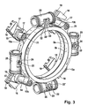
- Fig. 3
- die Darstellung gemäss Fig. 2 in Ansicht von der Gegenseite,
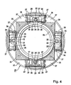
- Fig. 4
- eine Draufsicht auf eine Spannvorrichtung Fig. 2 und 3, in einer Teilschnitt-Darstellung,
- Fig. 5
- eine Schnittdarstellung in der Längsachse durch die Spannvorrichtung Fig. 4 und
- Fig. 6
- eine bevorzugte Ausführungsform eines pneumatischen Antriebs einer Spannvorrichtung.
- In Figur 1 ist eine vereinfacht dargestellte Lasermaschine mit LM bezeichnet. Der Laserstrahl L ist in bekannter Weise über eine Strahlführung und über Umlenkspiegel S in den Bearbeitungsraum der Maschine geführt. Auf einer Trägerplatte 2 befindet sich eine obere Spannvorrichtung 1 für Profile; die notwendige Energiezufuhr für die Spannvorrichtung erfolgt über Druckluftschläuche 3.
- Die Trägerplatte 2 ist seitlich durch Führungsflansche 4 und vorne durch auf ihr aufgeschweisste Führungsschienen 33 gleitfähig gehalten und in Richtung Z' vertikal verschiebbar. Die Spannvorrichtung 1 besteht im Wesentlichen aus Spannbacken 6 mit Rollen 7, welche drehbar über entsprechende Ringe auf der Trägerplatte 2 angeordnet sind. Die Spannbacken 6 sind leicht auswechselbar und mit Befestigungsschrauben 6' auf ihren Grundkörpern fixiert. Die Durchlässe für die Werkstücke sind mit D1 bzw. D2 bezeichnet.- Im Durchlass D1 ist ein Vierkant-Hohlprofil angedeutet; im Durchlass D2 ein Rohr. Die Verschiebewege dieser Rohmaterialien erfolgen in Pfeilrichtung über eine hinter der Spannvorrichtung angeordneten Beschickung (Handling System). Die Führungsschienen 33 sind durch ein Schutzwinkel 35 gegenüber groben Verschmutzungen und Beschädigungen durch abprallende Werkstücke und ausgeschnittene Teile geschützt.
- Die gesamte Spannvorrichtung 1 ist rotationsfähig ausgeführt, was durch einen mit ϕ bezeichneten Pfeil charakterisiert ist. Dieser Drehwinkel ϕ, in Bezug auf seine Referenzlage wird laufend durch einen Positionsgeber 34 überwacht und an eine an sich bekannte NC-Steuerung in der Lasermaschine gemeldet.
- Im unteren Bereich der Trägerplatte 2 befindet sich auf dem unteren Teil des Maschinenständers 32 ein Horizontalträger 8, auf dem ein sogenannter Lünettenträger 12 mit Lünetten 11 und eingelagerten Kugeln 11' horizontal verschieblich auf einer Führungsschiene 12' aufgebaut ist. Die Verschiebewege der Lünettenträger 12 sind durch Doppelpfeile aufgezeigt. Stirnseitig ist im Träger 8 ein Manometer 31 eingelassen, welches zur Überwachung des optimalen Eingangsdrucks der Druckluft und damit des Spanndrucks von hier nicht sichtbaren, steuerbaren Pneumatikzylindern dient. Die Kraftübertragung von den Pneumatikzylindern zu den Lünettenträgern 12 erfolgt über ebenfalls verdeckte Kolbenstangen.
- An der Trägerplatte 2 befinden sich seitlich angeordnet, einander gegenüberliegende Winkel 2', welche der Vertikalverstellung dienen. Ersichtlich ist im mittleren Teil des vorderen Winkels 2' ein Gegenlager 9' mit Trägern 9" eines über eine Schubstange 10 wirkenden elektromechanischen Linearantriebs 9. Dieser Antrieb 9 vermag die obere, erste Spannvorrichtung von ihrer Ausgangslage H0 in die Arbeitslage H1 nach unten zu verfahren. Der Verschiebeweg ist als Pfeil markiert und mit Z' bezeichnet.
- In nachfolgenden Figuren sind gleiche Funktionsteile mit gleichen Bezugsziffern versehen.
- Die in Fig. 1 ersichtlichen Spannringe 5 bestehen gemäss Fig. 2 aus einem ersten Ring 5a und einem zweiten Ring 5b. Der Ring 5a bewirkt eine Verstellung von einander gegenüberliegend angeordneten Grundbacken 16; der Ring 5b die Verstellung der - hier horizontal liegenden - Backen 16. Beide Ringe 5a und 5b sind unabhängig voneinander drehbar und weisen je vier zueinander um einen Zentriwinkel von 90° versetzte Rollenträger 13a bzw. 13b auf, in denen Rollachsen-Träger 14 mit endseitigen Rollen 15 eingesetzt sind.
- Die Rollen 15 liegen mit ihrem Aussenring in Grundbacken 16 eingelassenen Keilflächen 17 auf. Zwischen den jeweiligen Rollenträgern 13a resp. 13b ragen Nocken 22 mit Ausnehmungen 22' heraus, in welchen Kolbenbolzen 23 durch axial verschiebliche Doppelkolben 25 hindurchgeführt sind. Gesichert sind diese Kolben 25 jeweils auf der vom Ring 13a bzw. 13b abgewandten Seite mit üblichen Sicherungsringen 24, sogenannten "Seegerringen". Damit die Ringe 5a und 5b ihre Drehbewegung ausführen können sind die Ausnehmungen 22' als Langlöcher gestaltet.
- Die Grundbacken 16 besitzen eine stirnseitige, zentrale Spann-Nut 20 und seitliche Verzahnungen 18.
- Figur 3 zeigt die vorstehend beschriebene Anordnung von ihrer'Gegenseite. Gut ersichtlich sind hier die Keilflächen 17 und seitliche Nuten 19 in den Grundbacken 16, welche das Aufspannen (Festschrauben) der Spannbacken 6 erleichtern. Ebenfalls sieht man die Rollen 15 in den eingelassenen Keilflächen 16, sowie die Verschraubung der Rollenachsen-Träger 14. Um den Kolben 25 eine Linearbewegung zu ermöglichen und um diese in eine Rotationsbewegung der Ringe 5a und 5b umsetzen zu können, wirken hier wiederum die Kolbenbolzen 23 in Ausnehmungen 22' (Langlöcher) der Nocken 22.
- Die Draufsicht Fig. 4 zeigt die gleiche Anordnung, ebenfalls bei abgenommenen äusseren Abdeckring, jedoch aufgesetzt auf einen Futterkörper 29 und teilweise geschnitten. Zusätzlich sind hier Zylinderdeckel 27, welche die Kolben 25 dicht umschliessen. Die Zylinderdeckel 27 bilden einen Teil des Zylinderraums 28, sie sind mittels Positionierringen 26 in einer Bohrung 37 im Futterkörper 29, Fig. 4, in ihrer Lage definiert eingesetzt und führen die Doppelkolben 25. Rückseitig weisen die Kolben 25 je zwei Anschlüsse für die Druckluft auf, wobei diese Anschlüsse in Durchgangsbohrungen 36 im Futterkörper 29 münden und durch abgedichtete Flansche mit Hohlräumen über die Druckluftschläuche 3 mit Energie versorgt werden. Aufgeschraubt ist der Futterkörper 29 über Zentrierbohrungen 30 mit Befestigungsschrauben auf einer nicht dargestellten angetriebenen Hohlwelle.
- Der Längsschnitt nach Fig. 5, entlang eines Werkstücks W zeigt die Ausführungsform eines Antriebsflansches 45, auf welchen ein an sich bekannter Zahnkranz einwirkt und die Drehbewegung um den Winkel ϕ ermöglicht. Der eigentliche Futterkörper 29 zeigt den Zylinderflansch 5 mit seinen 1. und 2. Verstellringen 5a und 5b mit ihren Rollenträgern 13a, vgl. Fig. 2 und Fig. 3. Die Rollen 15, auf Rollenachsen 14 gelagert sind durch eingelassenen, versenkte Innensechskant-Schrauben 21 in den Rollenträgern festgeschraubt. Die Rollen 15 sind nach Art von Wälzlagern aufgebaut. Die Verstellringe 5a und 5b sind in einem Führungsring 5c aus Gleitmaterial gelagert und geführt.
- Ferner ist der Aufbau der Spannbacken 6 ersichtlich: Vor der Spann-Nut 20 liegt eine Grundbacke 16 mit einer feinen Verzahnung 18 in welche eine Gewindeplatte 40 einrastet. durch Schrauben 6' sind die Spannbacken 6 mit ihren Rollen 7 aufgesetzt und lassen sich, entsprechend den Abmessungen des Werkstücks W einstellen, so dass die Spannwege klein sind. Dadurch kann Stangenmaterial automatisch nachgeschoben und in der vorbestimmten Länge wieder gespannt werden. Zur Dämpfung von Schwingungen dient ein Dämpfungsring 43 mit eingelegten elastischen Ringen 44, welche durch Schrauben 46 geklemmt sind Der ringförmige Hohlraum 48 ist für grosse Durchlassweiten ausgelegt; das Futter 29 erlaubt das sichere spannen beliebiger Profile.
- Die Funktionsweise einer Spannvorrichtung gemäss Fig. 2 bis 5 ist folgende:
- Entsprechend dem zu spannenden Profil (Werkstück/Rohling) werden die Spannbacken 6 auf den Grundbacken 16, mit Spiel gegenüber dem Profil festgeschraubt. Durch Zuführung von Druckluft (gesteuert über die NC-Programmierung) werden die Druckluftschläuche 3 mit Druckluft versorgt und beaufschlagen Kolbenböden 25' (Fig. 2), so dass sich die Spannvorrichtung schliesst, d.h. die Spannbacken 6 fassen das Profil mit einer Kraft von zirka 60 kg pro Backe. Der Kraftfluss ist leicht ersichtlich; je zwei gegenüberliegende Doppelkolben 25 bewegen den Ring 5a und/oder 5b, so dass die Rollen 15 in den Keilflächen 16 abrollen und sich dadurch die Grundbacken 16 in ihren, im äusseren Futterkörper 29 eingelassenen, seitlichen Nuten 19 radial verschieben.
- Die dargestellte Ausführungsform erlaubt sehr kurze Spann-und Öffnungszeiten, so dass die Vorrichtung eine erhöhte Bearbeitungskadenz der Lasermaschine erlaubt.
- Die zweite Spannvorrichtung 11, 11', 12, vgl. Fig. 1 arbeitet ähnlich einer an sich bekannten Lünette und ist für rotationssymmetrische Werkstücke vorgesehen. Sie ist ebenfalls pneumatisch betätigt und kann leicht von ihrem Vertikalträger entfernt werden, wenn sie die erste Spannvorrichtung im Einsatz ist und stören könnte.
- Die Arbeitslage H1 lässt sich an das zum Einsatz gelangende "Handling-System" oder an die Form der Werkstücke anpassen.
- In Fig. 6 ist ein bevorzugtes Ausführungsbeispiel eines Pneumatikzylinders mit Doppelkolben 25 in der Bohrung 37 dargestellt. Im zentralen Bereich ist der Doppelkolben 25 durch eine Ausdrehung mit einem Ringraum 25" versehen und somit nur auf beiden Seiten geführt. Randseitig sind zudem Dichtringe 56 (O-Ringe) vorgesehen, die den Kolben 25 in seiner Bohrung 37 abdichten. Zylinderdeckel 27, jedoch hier mit einem vorstehenden Zapfen 27a können durch die Kolbenbewegung bis zu einem Anschlag 27b angefahren werden. Die Zylinderdeckel 27 besitzen ihrerseits periphere Dichtringe 53 (O-Ringe) und sind kraftschlüssig an Sicherungsringen 50 (Innen-Seegerringe) gehalten. Hierzu dienen Flansche 51 die mit Schrauben 52 die Zylinderdeckel 27 stationär fixieren.
- Die resultierenden Zylinderräume sind mit 28 bezeichnet und werden über den Zapfen 27a zugeordnete Lufteinlässe 54 mit Druckluft versorgt. Im Zentrum des Doppelkolbens 25 ist eine - dem Betrachter zugewandte - Aussparung 55 zu sehen, in der ein mit dem zweiten Ring 5a verbundener Nocken 22 in Kreisrichtung (durch Pfeile charakterisiert) bewegbar ist. Der hier nicht eingezeichnete Kolbenbolzen ist ebenfalls in einer Ausnehmung 22', einem Langloch, seitlich geführt.
- In gleicher Weise sind sämtliche vier Doppelkolben ausgeführt. Gegenüber der in Fig. 4 dargestellten Ausführungsform ergibt die Variante nach Fig. 6 eine bessere Ausnutzung des zur Verfügung stehenden Raums und damit höhere Verschiebe- bzw. Spannkräfte.
- Der ersten Spannvorrichtung 1 ist ein konventioneller Antrieb (Zahnkranz mit Servomotor) zugeordnet, so dass sich die Werkstücke mit dem Laserstrahl L im vollen Umfang vom zugeführten Profil abtrennen (schneiden) lassen. Die Drehzahl der Spannvorrichtung 1 kann kurzzeitig auf mehrere hundert Umdrehungen pro Minute hochgefahren werden, so dass auch ausgeschnittene Teile aus dem Werkstück durch Zentrifugalkräfte herausgeschleudert werden.
- Durch die Wahl der zur Laserbearbeitung optimal geeigneten Spannvorrichtung lassen sich die Be- und Entladezeiten der Maschine reduzieren. Ebenfalls kann die Umrüstzeit von einem Werkstücktyp zu einem anderen beträchtlich reduziert werden.
- Der Erfindungsgegenstand könnte auch mehrere und/oder auswechselbare Spannvorrichtungen umfassen, die auch über eine Kreisscheibe an Stelle einer Trägerplatte zuschaltbar sind.
-
- 1
- Spannvorrichtung für Profile
- 2
- Trägerplatte (vertikal verschieblich)
- 2'
- Winkel an 2
- 3
- Druckluftzuführung / Schläuche
- 4
- Führungsflansch zu 2'
- 5
- Zylinderflansch mit Futterkörper
- 5a
- 1. Verstellring
- 5b
- 2. Verstellring
- 5c
- Führungsring / Gleitflächen
- 6
- Backen / Spannbacken
- 6'
- Befestigungsschrauben für 6
- 7
- Rollen
- 8
- Horizontalträger
- 9
- Linearantrieb (elektromechanisch)
- 9'
- Gegenlager
- 9"
- Träger von 9'
- 10
- Schubstange
- 11
- Backen / Lünette
- 11'
- Gleitstücke / Kugeln in 11
- 12
- Lünettenträger
- 12'
- Führungsschiene
- 13a,13b
- Rollenträger
- 14
- Rollachsen-Träger
- 15
- Rollen
- 16
- Grundbacken
- 17
- Keilflächen in 16
- 18
- Verzahnung
- 19
- Seitliche Nuten in 16
- 20
- Spann-Nut
- 21
- Verschraubung von 14 (Innensechskant)
- 22
- Nocken
- 22'
- Ausnehmung in 22 (Langloch)
- 23
- Kolbenbolzen
- 24
- Sicherungsring mit Unterlegscheibe
- 25
- Doppelkolben (pneumatisch)
- 25'
- Kolbenboden
- 25"
- Ringraum (Ausdrehung)
- 26
- Positionierring
- 27
- Zylinderdeckel
- 27a
- Zapfen von 27
- 27b
- Anschlag von 27
- 28
- Zylinderraum
- 29
- Futterkörper
- 30
- Zentrierbohrungen / Bohrungen für Befestigungsschrauben
- 31
- Manometer (Druckluft)
- 32
- Maschinenständer / Ständer
- 33
- Führungsschienen
- 34
- Positionsgeber
- 35
- Schutzwinkel
- 36
- Durchgangsbohrungen
- 37
- Bohrung (Zylinderraum)
- 40
- Gewindeplatte
- 41
- Schnittfläche (Querschnitt)
- 42
- Ausnehmung für Zylinder 25
- 43
- Dämpfungsring
- 44
- elastische Ringe
- 45
- Antriebsflansch
- 46
- Schraube
- 48
- Hohlraum
- 50
- Sicherungsring (Innen-Seegerring)
- 51
- Flansch
- 52
- Schrauben mit Sicherungscheiben
- 53
- Dichtring (O-Ring)
- 54
- Lufteinlass (Druckluft)
- 55
- Aussparung
- 56
- Dichtring (O-Ring)
- D1
- Durchlass mit Führungsrollen
- D2
- Durchlass mit Lünette
- L
- Laserstrahl
- LM
- Lasermaschine
- H0
- Ausgangslage
- H1
- Arbeitslage / Arbeitsposition
- S
- Umlenkspiegel
- W
- Werkstück
- Z'
- Verschiebeweg von 2 (Hilfsachse)
- ϕ
- Drehwinkel von 1
Claims (10)
- Werkzeugmaschine zur Bearbeitung von länglichen Werkstücken mittels Laserstrahlen, insbesondere von Rohren, Stäben, Flach- und Hohlprofilen, wobei die Werkstücke während der Laserstrahlbearbeitung in einer Spannvorrichtung (1,11,12) zumindest partiell umschlossen, eingespannt oder gelagert sind, dadurch gekennzeichnet, dass eine erste Spannvorrichtung (1) vorwiegend für Stäbe und Profile und eine zweite Spannvorrichtung (11,12) vorwiegend für Werkstücke aus Rundmaterial vorgesehen ist und dass diese Spannvorrichtungen (1 bzw. 11,12) in einer Vertikalebene verschieblich und wahlweise zuschaltbar sind.
- Werkzeugmaschine nach Anspruch 1, dadurch gekennzeichnet, dass eine höhenverstellbare, vertikal angeordnete Trägerplatte (2) vorgesehen ist, welche zwei horizontale Durchlässe (D1,D2) aufweist, dass die Spannvorrichtungen (1;11,12 auf der Trägerplatte (2) angeordnet sind, dass die Trägerplatte (2) an Führungsflanschen (4) und an Führungsstäben (33) gleitfähig gehalten ist und an dass an dieser Trägerplatte (2) wenigstens eine Schubstange (10) eines am Grundgestell der Werkzeugmaschine (LM,32) angeordneten Linearantriebs (9,9',10) angreift, der die Durchlässe (D1 resp. D2) auf die jeweilige Bearbeitungshöhe (H1) des Werkstücks einstellt.
- Werkzeugmaschine nach Anspruch 1, dadurch gekennzeichnet, dass die Backen (6,6';11) der beiden Spannvorrichtungen (1;11,12) pneumatisch betätigt und selbstzentrierend sind.
- Werkzeugmaschine nach Anspruch 3, dadurch gekennzeichnet, dass die erste Spannvorrichtung (1) einen ersten Spannring (5a) zur paarweisen Verstellung von einander gegenüberliegenden vertikalen Spannbacken (6) und einen zweiten Spannring (5b) zur Verstellung von einander gegenüberliegenden horizontalen Spannbacken (6) aufweist.
- Werkzeugmaschine nach Anspruch 4, dadurch gekennzeichnet, dass die Spannringe (5a,5b) über in einem Futterkörper (29) angeordneten Doppelkolben (25) verdrehbar sind.
- Werkzeugmaschine nach einem der Ansprüche 3 oder 4, dadurch gekennzeichnet, dass in Grundbacken (16), welche die Spannbacken (6) tragen, Keilflächen (17) eingelassen sind, in denen Rollen (15) lagern und welche Drehbewegungen der Spannringe (5a,5b) in orthogonale Spannbewegungen umsetzen.
- Werkzeugmaschine nach wenigstens einem der Ansprüche 3 bis 6, dadurch gekennzeichnet, dass die Grundbacken (16) auf ihrer Vorderseite je eine Spann-Nut (20) und zwei Reihen Verzahnungen (18) aufweisen.
- Werkzeugmaschine nach Anspruch 1, dadurch gekennzeichnet, dass die Spannvorrichtung (1) Druckluftzuführungen (3) aufweist, welche in zueinander durch Ringdichtungen abgedichteten Flanschen (29) mit Hohlräumen münden und über Durchgangsbohrungen (36) die Kolben (25) speisen und dass die Spannvorrichtung (1) mit einem Antrieb versehen um wenigstens einen Drehwinkel (ϕ) von 360° drehbar ist.
- Werkzeugmaschine nach Anspruch 1, dadurch gekennzeichnet, dass die zweite Spannvorrichtung (11,12) maschinenfest angeordnet ist, und dass diese bei der Benutzung der ersten Spannvorrichtung (1) entweder auf ihre maximale Ausladung ausgefahren oder entfernt ist.
- Werkzeugmaschine nach Anspruch 9, dadurch gekennzeichnet, dass Backen (11) der Spannvorrichtung auf ihrer dem Werkstück zugewandten Oberfläche leicht aus dieser herausragende Gleitstücke (11') aufweisen.
Applications Claiming Priority (3)
| Application Number | Priority Date | Filing Date | Title |
|---|---|---|---|
| US41927602P | 2002-10-17 | 2002-10-17 | |
| US419276P | 2002-10-17 | ||
| PCT/CH2003/000679 WO2004035258A1 (de) | 2002-10-17 | 2003-10-17 | Spannvorrichtung für längliche werkstücke in einer laserstrahlmaschine |
Publications (2)
| Publication Number | Publication Date |
|---|---|
| EP1554079A1 EP1554079A1 (de) | 2005-07-20 |
| EP1554079B1 true EP1554079B1 (de) | 2006-05-03 |
Family
ID=32108058
Family Applications (1)
| Application Number | Title | Priority Date | Filing Date |
|---|---|---|---|
| EP03750227A Expired - Lifetime EP1554079B1 (de) | 2002-10-17 | 2003-10-17 | Spannvorrichtung für längliche werkstücke in einer laserstrahlmaschine |
Country Status (6)
| Country | Link |
|---|---|
| US (1) | US7040629B2 (de) |
| EP (1) | EP1554079B1 (de) |
| AT (1) | ATE324963T1 (de) |
| AU (1) | AU2003269662A1 (de) |
| DE (1) | DE50303242D1 (de) |
| WO (1) | WO2004035258A1 (de) |
Families Citing this family (23)
| Publication number | Priority date | Publication date | Assignee | Title |
|---|---|---|---|---|
| HU226381B1 (hu) * | 2004-08-25 | 2008-10-28 | Jozsef Dr Tajnafoei | Befogótokmány a rugalmas gyártáshoz |
| US8371903B2 (en) * | 2008-12-02 | 2013-02-12 | G.D.O. Inc. | Portable demilitarization apparatus for segmenting ordnance |
| US8776651B2 (en) | 2009-02-24 | 2014-07-15 | Bystronic Laser Ag | Process for working of work-pieces by means of cutting fluid-jet |
| JP2013509301A (ja) * | 2009-11-02 | 2013-03-14 | メガスター・テクノロジーズ・エルエルシー | ケーシングおよび小径管類または小径パイプの位置ずれ摩擦攪拌溶接 |
| CH707775A1 (de) * | 2013-03-18 | 2014-09-30 | Rieter Ag Maschf | Vorrichtung zur Bearbeitung von Laufflächen an Kopfendstücken von Wanderdeckeln. |
| DE102013214017B3 (de) * | 2013-07-17 | 2014-09-11 | Trumpf Werkzeugmaschinen Gmbh + Co. Kg | Positioniervorrichtung zum Positionieren von Werkstücken, Werkzeugmaschine mit einer derartigen Positioniervorrichtung, Verfahren zum Positionieren von Werkstücken |
| CN104477243B (zh) * | 2014-10-31 | 2017-03-15 | 芜湖普威技研有限公司 | 汽车前横梁装配装置 |
| CN107538040B (zh) * | 2016-06-24 | 2019-12-17 | 上海宝冶集团有限公司 | 在环形工件开孔和焊接的自动变位加工装置及加工方法 |
| US10337814B1 (en) | 2016-08-15 | 2019-07-02 | The United States Of America As Represented By The Secretary Of The Navy | Dearmer positioning system |
| CN108817710B (zh) * | 2018-07-20 | 2024-03-19 | 江南工业集团有限公司 | 一种薄壁壳体激光焊接装夹装置和操作方法 |
| CN108747127B (zh) * | 2018-08-23 | 2024-01-19 | 唐山鑫万达实业股份有限公司 | 一种可变式支撑割台圆形喂入滚筒的焊接装置及其使用方法 |
| CN109262191B (zh) * | 2018-11-30 | 2023-12-29 | 合肥哈工易科自动化科技有限公司 | 自动焊接翻转变位机 |
| CN111745177A (zh) * | 2019-03-29 | 2020-10-09 | 日本碍子株式会社 | 圆柱状工件的开孔装置及其开孔方法、圆柱状产品的制造方法以及圆柱状工件的检查方法 |
| DE102019112953B4 (de) * | 2019-05-16 | 2022-01-27 | SCHUNK GmbH & Co. KG Spann- Greiftechnik | Spannfutter für Werkzeugmaschinen |
| US11090769B2 (en) * | 2019-06-24 | 2021-08-17 | Chiao Sheng Machinery Co., Ltd. | Pipe clamping apparatus of pipe processing machine |
| CN111136295A (zh) * | 2020-01-14 | 2020-05-12 | 武汉天琪激光设备制造有限公司 | 一种用于管材加工设备的气动卡盘 |
| ES2985371T3 (es) * | 2020-06-26 | 2024-11-05 | Eew Special Pipe Constructions Gmbh | Dispositivo de sujeción para secciones de tubo soldadas con costura longitudinal |
| JP7592366B2 (ja) | 2021-03-25 | 2024-12-02 | 株式会社ディスコ | クランプ治具及び研削方法 |
| CN113458595B (zh) * | 2021-08-05 | 2024-12-17 | 领曼机械科技(常州)有限公司 | 一种齿轮齿条同步带激光切管机卡盘及激光切管机 |
| CN116174927B (zh) * | 2021-11-26 | 2026-04-07 | 常州比优特机械科技有限公司 | 激光切管卡盘 |
| CN113953697B (zh) * | 2021-12-21 | 2022-03-15 | 倍得福机械科技(常州)股份有限公司 | 一种用于激光切割机的前卡盘结构 |
| EP4230340A1 (de) * | 2022-02-17 | 2023-08-23 | Bystronic Laser AG | Haltevorrichtung für laserbearbeitungsmaschine |
| CN116618933A (zh) * | 2023-06-19 | 2023-08-22 | 北京圣龙博睿科技有限公司 | 同心对中装置及焊接设备 |
Family Cites Families (27)
| Publication number | Priority date | Publication date | Assignee | Title |
|---|---|---|---|---|
| US1469360A (en) * | 1920-07-23 | 1923-10-02 | Niles Bement Pond Co | Clamp and grip chuck |
| US2147800A (en) * | 1937-01-08 | 1939-02-21 | Paul H Sadowski | Work holder |
| US2431101A (en) * | 1942-09-29 | 1947-11-18 | John A Woods | Apparatus for fabricating pipe units and the like |
| US2451705A (en) * | 1947-09-29 | 1948-10-19 | Adair Russell Sandford | Control device for hydraulic steady-rest chucks |
| US3083024A (en) * | 1961-09-11 | 1963-03-26 | Pipe Machinery Company | Roll-over chuck |
| US3318594A (en) * | 1964-01-08 | 1967-05-09 | Gen Electric | Gripping device |
| US3771393A (en) * | 1971-06-23 | 1973-11-13 | Charles Gatto | Cutting apparatus and method therefor |
| US4593451A (en) * | 1978-12-04 | 1986-06-10 | Roberts Royce Glen | Apparatus for cleaning large pipe threads |
| US4277231A (en) * | 1979-09-21 | 1981-07-07 | Gordon John H | Method and apparatus for pressure forming pipe bells |
| JPS56146603A (en) * | 1980-04-07 | 1981-11-14 | Kawasaki Steel Corp | Chucking device |
| US4574350A (en) * | 1982-05-19 | 1986-03-04 | At&T Bell Laboratories | Shared resource locking apparatus |
| DE3504713A1 (de) | 1985-02-12 | 1986-08-14 | Wolfgang Dipl.-Phys. Dr.-Ing. 4800 Bielefeld Lindemann | Fasanlage zum anfassen der axialen enden stangenfoermigen gutes |
| US4684310A (en) * | 1985-08-06 | 1987-08-04 | Stange Charles E | Wheel manipulator |
| FR2587926B1 (fr) | 1985-10-01 | 1989-12-08 | Aerospatiale | Procede et machine de tronconnage et d'ebavurage de tubes a mettre au gabarit |
| CH677332A5 (en) | 1988-10-28 | 1991-05-15 | Bystronic Laser Ag | Laser machining system - has rotary workpiece drive unit pivot mounted at end of table to allow retraction when not in use |
| JPH03221311A (ja) * | 1990-01-23 | 1991-09-30 | Mitsubishi Heavy Ind Ltd | ミーリング式走行鋼管切断機 |
| US5180274A (en) * | 1990-05-07 | 1993-01-19 | Vix Design Products, Inc. | Wheel handling apparatus |
| US5540526A (en) * | 1994-09-06 | 1996-07-30 | Leblond Makino Machine Tool Company | Fluid bearing tool and a method for forming the same |
| IT1285079B1 (it) * | 1995-05-05 | 1998-06-03 | Giddings & Lewis | Sistema attuatore per la compensazione dell'allineamento di una macchina. |
| FR2743741B1 (fr) * | 1996-01-23 | 1998-03-06 | Renault Automation | Structure logique d'une machine-outil d'usinage a grande vitesse du type porte-broche |
| DE59701400D1 (de) * | 1997-01-17 | 2000-05-11 | Forkardt Deutschland Gmbh | Kraftbetätigtes Spannfutter |
| DE19857013C2 (de) * | 1998-12-09 | 2001-09-06 | Schwaebische Werkzeugmaschinen | Werkzeugmaschine mit horizontaler Arbeitsspindel |
| JP3168328B2 (ja) * | 1999-07-12 | 2001-05-21 | ホーコス株式会社 | 工作機械及び、そのカバー装置 |
| ES2173853T3 (es) * | 2000-08-21 | 2002-11-01 | Mini Ricerca Scient Tecnolog | Unidad de produccion de alta velocidad para operaciones de mecanizacion. |
| DE10049810B4 (de) * | 2000-10-09 | 2004-07-01 | Honsberg Lamb Sonderwerkzeugmaschinen Gmbh | Werkzeugmaschine |
| US6478136B2 (en) * | 2001-01-08 | 2002-11-12 | Nikon Corporation | Method and apparatus for automatically transporting and precisely positioning work pieces at processing stations |
| ES2241703T3 (es) * | 2001-03-09 | 2005-11-01 | Cross Huller Gmbh | Maquina herramienta. |
-
2003
- 2003-10-14 US US10/685,271 patent/US7040629B2/en not_active Expired - Lifetime
- 2003-10-17 AU AU2003269662A patent/AU2003269662A1/en not_active Abandoned
- 2003-10-17 AT AT03750227T patent/ATE324963T1/de not_active IP Right Cessation
- 2003-10-17 EP EP03750227A patent/EP1554079B1/de not_active Expired - Lifetime
- 2003-10-17 WO PCT/CH2003/000679 patent/WO2004035258A1/de not_active Ceased
- 2003-10-17 DE DE50303242T patent/DE50303242D1/de not_active Expired - Lifetime
Also Published As
| Publication number | Publication date |
|---|---|
| WO2004035258A1 (de) | 2004-04-29 |
| US7040629B2 (en) | 2006-05-09 |
| EP1554079A1 (de) | 2005-07-20 |
| AU2003269662A1 (en) | 2004-05-04 |
| DE50303242D1 (de) | 2006-06-08 |
| ATE324963T1 (de) | 2006-06-15 |
| US20040076486A1 (en) | 2004-04-22 |
Similar Documents
| Publication | Publication Date | Title |
|---|---|---|
| EP1554079A1 (de) | Spannvorrichtung für längliche werkstücke in einer laserstrahlmaschine | |
| EP0480299B1 (de) | Mehrfachspanner zum Festspannen von mindestens zwei Werkstücken | |
| DE2257384C3 (de) | Spannfutter für Drehmaschinen u.dgl. Werkzeugmaschinen | |
| DE102019004527A1 (de) | Vorrichtung zum Spannen von Werkstücken für Bearbeitungszentren | |
| EP0739672A2 (de) | Spannvorrichtung zum umfangsseitigen Spannen von Werkstücken mit beliebiger Umfangskontur | |
| DE1146724B (de) | Spannfutter fuer Werkzeugmaschinen | |
| CH657567A5 (de) | Revolver-stanze. | |
| DE2902421C2 (de) | ||
| DE19916765A1 (de) | Handhabungswerkzeug für eine Werkzeugmaschine | |
| DE3735858A1 (de) | Vorrichtung zum einbringen von befestigungsbohrungen oder ventilbohrungen in eine schuessel bzw. eine felge eines rades eines kraftfahrzeuges | |
| DE2754357C2 (de) | ||
| DE10163365B4 (de) | Spannfutter zum Festspannen dünner, scheibenförmiger Werkstücke | |
| DE10135233A1 (de) | Ringmaschine | |
| EP0378805B1 (de) | Verfahren und Vorrichtung zum Aufspannen instabiler Teile | |
| DE19936502C1 (de) | Vorrichtung und Verfahren zur schwenkbaren Werkstückzuführung in den Arbeitsbereich einer Werkzeugmaschine | |
| DE3042400A1 (de) | Werkzeugmaschine zur spanabhebenden bearbeitung | |
| DE3329942C1 (de) | Spannvorrichtung für insbes. spanabhebend zu bearbeitende Werkstücke | |
| EP3251788B1 (de) | Vorrichtung zum abstützen eines zu bearbeitenden werkstücks | |
| DE3708363A1 (de) | Spannfutter fuer werkzeugmaschinen | |
| EP1038618B1 (de) | Werkzeugkopf für eine Drehmaschine | |
| DE2158427C3 (de) | Schwenkfutter für Werkzeugmaschinen | |
| DE2900009A1 (de) | Zentrierspannstoecke in senkrechter anordnung mit ladeeinrichtung fuer werkzeugmaschinen | |
| DE20313816U1 (de) | Mittenspannvorrichtung | |
| EP2759376B1 (de) | Anordnung mit Spannvorrichtung zum Spannen eines eine Lageröffnung aufweisenden Motorbauteils | |
| DE3911073C1 (de) |
Legal Events
| Date | Code | Title | Description |
|---|---|---|---|
| PUAI | Public reference made under article 153(3) epc to a published international application that has entered the european phase |
Free format text: ORIGINAL CODE: 0009012 |
|
| AK | Designated contracting states |
Kind code of ref document: A1 Designated state(s): AT BE BG CH CY CZ DE DK EE ES FI FR GB GR HU IE IT LI LU MC NL PT RO SE SI SK TR |
|
| AX | Request for extension of the european patent |
Extension state: AL LT LV MK |
|
| 17P | Request for examination filed |
Effective date: 20050429 |
|
| GRAP | Despatch of communication of intention to grant a patent |
Free format text: ORIGINAL CODE: EPIDOSNIGR1 |
|
| DAX | Request for extension of the european patent (deleted) | ||
| GRAS | Grant fee paid |
Free format text: ORIGINAL CODE: EPIDOSNIGR3 |
|
| GRAA | (expected) grant |
Free format text: ORIGINAL CODE: 0009210 |
|
| AK | Designated contracting states |
Kind code of ref document: B1 Designated state(s): AT BE BG CH CY CZ DE DK EE ES FI FR GB GR HU IE IT LI LU MC NL PT RO SE SI SK TR |
|
| PG25 | Lapsed in a contracting state [announced via postgrant information from national office to epo] |
Ref country code: SK Free format text: LAPSE BECAUSE OF FAILURE TO SUBMIT A TRANSLATION OF THE DESCRIPTION OR TO PAY THE FEE WITHIN THE PRESCRIBED TIME-LIMIT Effective date: 20060503 Ref country code: IE Free format text: LAPSE BECAUSE OF FAILURE TO SUBMIT A TRANSLATION OF THE DESCRIPTION OR TO PAY THE FEE WITHIN THE PRESCRIBED TIME-LIMIT Effective date: 20060503 Ref country code: IT Free format text: LAPSE BECAUSE OF FAILURE TO SUBMIT A TRANSLATION OF THE DESCRIPTION OR TO PAY THE FEE WITHIN THE PRESCRIBED TIME-LIMIT;WARNING: LAPSES OF ITALIAN PATENTS WITH EFFECTIVE DATE BEFORE 2007 MAY HAVE OCCURRED AT ANY TIME BEFORE 2007. THE CORRECT EFFECTIVE DATE MAY BE DIFFERENT FROM THE ONE RECORDED. Effective date: 20060503 Ref country code: RO Free format text: LAPSE BECAUSE OF FAILURE TO SUBMIT A TRANSLATION OF THE DESCRIPTION OR TO PAY THE FEE WITHIN THE PRESCRIBED TIME-LIMIT Effective date: 20060503 Ref country code: CZ Free format text: LAPSE BECAUSE OF FAILURE TO SUBMIT A TRANSLATION OF THE DESCRIPTION OR TO PAY THE FEE WITHIN THE PRESCRIBED TIME-LIMIT Effective date: 20060503 Ref country code: NL Free format text: LAPSE BECAUSE OF FAILURE TO SUBMIT A TRANSLATION OF THE DESCRIPTION OR TO PAY THE FEE WITHIN THE PRESCRIBED TIME-LIMIT Effective date: 20060503 Ref country code: SI Free format text: LAPSE BECAUSE OF FAILURE TO SUBMIT A TRANSLATION OF THE DESCRIPTION OR TO PAY THE FEE WITHIN THE PRESCRIBED TIME-LIMIT Effective date: 20060503 Ref country code: FI Free format text: LAPSE BECAUSE OF FAILURE TO SUBMIT A TRANSLATION OF THE DESCRIPTION OR TO PAY THE FEE WITHIN THE PRESCRIBED TIME-LIMIT Effective date: 20060503 |
|
| REG | Reference to a national code |
Ref country code: GB Ref legal event code: FG4D Free format text: NOT ENGLISH |
|
| REG | Reference to a national code |
Ref country code: CH Ref legal event code: EP |
|
| REF | Corresponds to: |
Ref document number: 50303242 Country of ref document: DE Date of ref document: 20060608 Kind code of ref document: P |
|
| REG | Reference to a national code |
Ref country code: IE Ref legal event code: FG4D Free format text: LANGUAGE OF EP DOCUMENT: GERMAN |
|
| REG | Reference to a national code |
Ref country code: CH Ref legal event code: NV Representative=s name: PPS POLYVALENT PATENT SERVICE AG |
|
| PG25 | Lapsed in a contracting state [announced via postgrant information from national office to epo] |
Ref country code: SE Free format text: LAPSE BECAUSE OF FAILURE TO SUBMIT A TRANSLATION OF THE DESCRIPTION OR TO PAY THE FEE WITHIN THE PRESCRIBED TIME-LIMIT Effective date: 20060803 Ref country code: DK Free format text: LAPSE BECAUSE OF FAILURE TO SUBMIT A TRANSLATION OF THE DESCRIPTION OR TO PAY THE FEE WITHIN THE PRESCRIBED TIME-LIMIT Effective date: 20060803 |
|
| PG25 | Lapsed in a contracting state [announced via postgrant information from national office to epo] |
Ref country code: ES Free format text: LAPSE BECAUSE OF FAILURE TO SUBMIT A TRANSLATION OF THE DESCRIPTION OR TO PAY THE FEE WITHIN THE PRESCRIBED TIME-LIMIT Effective date: 20060814 |
|
| GBT | Gb: translation of ep patent filed (gb section 77(6)(a)/1977) |
Effective date: 20060814 |
|
| PG25 | Lapsed in a contracting state [announced via postgrant information from national office to epo] |
Ref country code: PT Free format text: LAPSE BECAUSE OF FAILURE TO SUBMIT A TRANSLATION OF THE DESCRIPTION OR TO PAY THE FEE WITHIN THE PRESCRIBED TIME-LIMIT Effective date: 20061003 |
|
| PG25 | Lapsed in a contracting state [announced via postgrant information from national office to epo] |
Ref country code: MC Free format text: LAPSE BECAUSE OF NON-PAYMENT OF DUE FEES Effective date: 20061031 |
|
| NLV1 | Nl: lapsed or annulled due to failure to fulfill the requirements of art. 29p and 29m of the patents act | ||
| ET | Fr: translation filed | ||
| REG | Reference to a national code |
Ref country code: IE Ref legal event code: FD4D |
|
| PLBE | No opposition filed within time limit |
Free format text: ORIGINAL CODE: 0009261 |
|
| STAA | Information on the status of an ep patent application or granted ep patent |
Free format text: STATUS: NO OPPOSITION FILED WITHIN TIME LIMIT |
|
| 26N | No opposition filed |
Effective date: 20070206 |
|
| BERE | Be: lapsed |
Owner name: BYSTRONIC LASER A.G. Effective date: 20061031 |
|
| PG25 | Lapsed in a contracting state [announced via postgrant information from national office to epo] |
Ref country code: AT Free format text: LAPSE BECAUSE OF NON-PAYMENT OF DUE FEES Effective date: 20061017 |
|
| PG25 | Lapsed in a contracting state [announced via postgrant information from national office to epo] |
Ref country code: GR Free format text: LAPSE BECAUSE OF FAILURE TO SUBMIT A TRANSLATION OF THE DESCRIPTION OR TO PAY THE FEE WITHIN THE PRESCRIBED TIME-LIMIT Effective date: 20060804 |
|
| PG25 | Lapsed in a contracting state [announced via postgrant information from national office to epo] |
Ref country code: EE Free format text: LAPSE BECAUSE OF FAILURE TO SUBMIT A TRANSLATION OF THE DESCRIPTION OR TO PAY THE FEE WITHIN THE PRESCRIBED TIME-LIMIT Effective date: 20060503 Ref country code: BG Free format text: LAPSE BECAUSE OF FAILURE TO SUBMIT A TRANSLATION OF THE DESCRIPTION OR TO PAY THE FEE WITHIN THE PRESCRIBED TIME-LIMIT Effective date: 20060803 |
|
| PG25 | Lapsed in a contracting state [announced via postgrant information from national office to epo] |
Ref country code: TR Free format text: LAPSE BECAUSE OF FAILURE TO SUBMIT A TRANSLATION OF THE DESCRIPTION OR TO PAY THE FEE WITHIN THE PRESCRIBED TIME-LIMIT Effective date: 20060503 Ref country code: LU Free format text: LAPSE BECAUSE OF NON-PAYMENT OF DUE FEES Effective date: 20061017 Ref country code: HU Free format text: LAPSE BECAUSE OF FAILURE TO SUBMIT A TRANSLATION OF THE DESCRIPTION OR TO PAY THE FEE WITHIN THE PRESCRIBED TIME-LIMIT Effective date: 20061104 |
|
| PG25 | Lapsed in a contracting state [announced via postgrant information from national office to epo] |
Ref country code: CY Free format text: LAPSE BECAUSE OF FAILURE TO SUBMIT A TRANSLATION OF THE DESCRIPTION OR TO PAY THE FEE WITHIN THE PRESCRIBED TIME-LIMIT Effective date: 20060503 |
|
| PG25 | Lapsed in a contracting state [announced via postgrant information from national office to epo] |
Ref country code: BE Free format text: LAPSE BECAUSE OF FAILURE TO SUBMIT A TRANSLATION OF THE DESCRIPTION OR TO PAY THE FEE WITHIN THE PRESCRIBED TIME-LIMIT Effective date: 20061031 |
|
| REG | Reference to a national code |
Ref country code: CH Ref legal event code: NV Representative=s name: ROSENICH PAUL; GISLER CHRISTIAN PATENTBUERO PAUL R |
|
| REG | Reference to a national code |
Ref country code: DE Ref legal event code: R082 Ref document number: 50303242 Country of ref document: DE Representative=s name: PATENTBUERO PAUL ROSENICH AG, LI |
|
| REG | Reference to a national code |
Ref country code: FR Ref legal event code: PLFP Year of fee payment: 13 |
|
| REG | Reference to a national code |
Ref country code: FR Ref legal event code: PLFP Year of fee payment: 14 |
|
| REG | Reference to a national code |
Ref country code: FR Ref legal event code: PLFP Year of fee payment: 15 |
|
| REG | Reference to a national code |
Ref country code: DE Ref legal event code: R082 Ref document number: 50303242 Country of ref document: DE Representative=s name: PATENTBUERO PAUL ROSENICH AG, LI |
|
| REG | Reference to a national code |
Ref country code: FR Ref legal event code: PLFP Year of fee payment: 16 |
|
| PGFP | Annual fee paid to national office [announced via postgrant information from national office to epo] |
Ref country code: FR Payment date: 20180928 Year of fee payment: 16 |
|
| PGFP | Annual fee paid to national office [announced via postgrant information from national office to epo] |
Ref country code: BE Payment date: 20181126 Year of fee payment: 13 Ref country code: GB Payment date: 20181017 Year of fee payment: 16 |
|
| PGFP | Annual fee paid to national office [announced via postgrant information from national office to epo] |
Ref country code: DE Payment date: 20191001 Year of fee payment: 17 |
|
| PGFP | Annual fee paid to national office [announced via postgrant information from national office to epo] |
Ref country code: IT Payment date: 20191009 Year of fee payment: 17 |
|
| REG | Reference to a national code |
Ref country code: CH Ref legal event code: PL |
|
| PG25 | Lapsed in a contracting state [announced via postgrant information from national office to epo] |
Ref country code: CH Free format text: LAPSE BECAUSE OF NON-PAYMENT OF DUE FEES Effective date: 20191031 Ref country code: LI Free format text: LAPSE BECAUSE OF NON-PAYMENT OF DUE FEES Effective date: 20191031 |
|
| GBPC | Gb: european patent ceased through non-payment of renewal fee |
Effective date: 20191017 |
|
| PG25 | Lapsed in a contracting state [announced via postgrant information from national office to epo] |
Ref country code: FR Free format text: LAPSE BECAUSE OF NON-PAYMENT OF DUE FEES Effective date: 20191031 Ref country code: GB Free format text: LAPSE BECAUSE OF NON-PAYMENT OF DUE FEES Effective date: 20191017 |
|
| REG | Reference to a national code |
Ref country code: DE Ref legal event code: R119 Ref document number: 50303242 Country of ref document: DE |
|
| PG25 | Lapsed in a contracting state [announced via postgrant information from national office to epo] |
Ref country code: DE Free format text: LAPSE BECAUSE OF NON-PAYMENT OF DUE FEES Effective date: 20210501 |
|
| PG25 | Lapsed in a contracting state [announced via postgrant information from national office to epo] |
Ref country code: IT Free format text: LAPSE BECAUSE OF NON-PAYMENT OF DUE FEES Effective date: 20201017 |