EP1553273A2 - Système de refroidissement - Google Patents
Système de refroidissement Download PDFInfo
- Publication number
- EP1553273A2 EP1553273A2 EP04028830A EP04028830A EP1553273A2 EP 1553273 A2 EP1553273 A2 EP 1553273A2 EP 04028830 A EP04028830 A EP 04028830A EP 04028830 A EP04028830 A EP 04028830A EP 1553273 A2 EP1553273 A2 EP 1553273A2
- Authority
- EP
- European Patent Office
- Prior art keywords
- fluid
- heat exchanger
- cooling system
- housing
- cooling
- Prior art date
- Legal status (The legal status is an assumption and is not a legal conclusion. Google has not performed a legal analysis and makes no representation as to the accuracy of the status listed.)
- Granted
Links
- 238000001816 cooling Methods 0.000 title claims abstract description 86
- 239000012530 fluid Substances 0.000 claims abstract description 84
- 238000002485 combustion reaction Methods 0.000 claims abstract description 21
- 239000007788 liquid Substances 0.000 claims abstract description 5
- 239000012809 cooling fluid Substances 0.000 claims description 10
- 238000000926 separation method Methods 0.000 claims description 3
- 239000003570 air Substances 0.000 description 87
- 239000002826 coolant Substances 0.000 description 12
- 230000015572 biosynthetic process Effects 0.000 description 4
- 210000000988 bone and bone Anatomy 0.000 description 3
- XAGFODPZIPBFFR-UHFFFAOYSA-N aluminium Chemical compound [Al] XAGFODPZIPBFFR-UHFFFAOYSA-N 0.000 description 1
- 229910052782 aluminium Inorganic materials 0.000 description 1
- 239000012080 ambient air Substances 0.000 description 1
- 238000010276 construction Methods 0.000 description 1
- 238000010438 heat treatment Methods 0.000 description 1
- 238000004519 manufacturing process Methods 0.000 description 1
- 238000005192 partition Methods 0.000 description 1
- 238000005496 tempering Methods 0.000 description 1
Images


Classifications
-
- F—MECHANICAL ENGINEERING; LIGHTING; HEATING; WEAPONS; BLASTING
- F28—HEAT EXCHANGE IN GENERAL
- F28D—HEAT-EXCHANGE APPARATUS, NOT PROVIDED FOR IN ANOTHER SUBCLASS, IN WHICH THE HEAT-EXCHANGE MEDIA DO NOT COME INTO DIRECT CONTACT
- F28D9/00—Heat-exchange apparatus having stationary plate-like or laminated conduit assemblies for both heat-exchange media, the media being in contact with different sides of a conduit wall
- F28D9/0031—Heat-exchange apparatus having stationary plate-like or laminated conduit assemblies for both heat-exchange media, the media being in contact with different sides of a conduit wall the conduits for one heat-exchange medium being formed by paired plates touching each other
- F28D9/0043—Heat-exchange apparatus having stationary plate-like or laminated conduit assemblies for both heat-exchange media, the media being in contact with different sides of a conduit wall the conduits for one heat-exchange medium being formed by paired plates touching each other the plates having openings therein for circulation of at least one heat-exchange medium from one conduit to another
-
- F—MECHANICAL ENGINEERING; LIGHTING; HEATING; WEAPONS; BLASTING
- F02—COMBUSTION ENGINES; HOT-GAS OR COMBUSTION-PRODUCT ENGINE PLANTS
- F02B—INTERNAL-COMBUSTION PISTON ENGINES; COMBUSTION ENGINES IN GENERAL
- F02B29/00—Engines characterised by provision for charging or scavenging not provided for in groups F02B25/00, F02B27/00 or F02B33/00 - F02B39/00; Details thereof
- F02B29/04—Cooling of air intake supply
- F02B29/0406—Layout of the intake air cooling or coolant circuit
- F02B29/0412—Multiple heat exchangers arranged in parallel or in series
-
- F—MECHANICAL ENGINEERING; LIGHTING; HEATING; WEAPONS; BLASTING
- F02—COMBUSTION ENGINES; HOT-GAS OR COMBUSTION-PRODUCT ENGINE PLANTS
- F02M—SUPPLYING COMBUSTION ENGINES IN GENERAL WITH COMBUSTIBLE MIXTURES OR CONSTITUENTS THEREOF
- F02M26/00—Engine-pertinent apparatus for adding exhaust gases to combustion-air, main fuel or fuel-air mixture, e.g. by exhaust gas recirculation [EGR] systems
- F02M26/13—Arrangement or layout of EGR passages, e.g. in relation to specific engine parts or for incorporation of accessories
- F02M26/22—Arrangement or layout of EGR passages, e.g. in relation to specific engine parts or for incorporation of accessories with coolers in the recirculation passage
- F02M26/23—Layout, e.g. schematics
- F02M26/24—Layout, e.g. schematics with two or more coolers
-
- F—MECHANICAL ENGINEERING; LIGHTING; HEATING; WEAPONS; BLASTING
- F28—HEAT EXCHANGE IN GENERAL
- F28F—DETAILS OF HEAT-EXCHANGE AND HEAT-TRANSFER APPARATUS, OF GENERAL APPLICATION
- F28F2250/00—Arrangements for modifying the flow of the heat exchange media, e.g. flow guiding means; Particular flow patterns
- F28F2250/10—Particular pattern of flow of the heat exchange media
- F28F2250/104—Particular pattern of flow of the heat exchange media with parallel flow
-
- Y—GENERAL TAGGING OF NEW TECHNOLOGICAL DEVELOPMENTS; GENERAL TAGGING OF CROSS-SECTIONAL TECHNOLOGIES SPANNING OVER SEVERAL SECTIONS OF THE IPC; TECHNICAL SUBJECTS COVERED BY FORMER USPC CROSS-REFERENCE ART COLLECTIONS [XRACs] AND DIGESTS
- Y02—TECHNOLOGIES OR APPLICATIONS FOR MITIGATION OR ADAPTATION AGAINST CLIMATE CHANGE
- Y02T—CLIMATE CHANGE MITIGATION TECHNOLOGIES RELATED TO TRANSPORTATION
- Y02T10/00—Road transport of goods or passengers
- Y02T10/10—Internal combustion engine [ICE] based vehicles
- Y02T10/12—Improving ICE efficiencies
Definitions
- the invention relates to a cooling system for an internal combustion engine, in particular for a motor vehicle, with several circuits with heat exchangers for several fluids.
- Such cooling systems are used for example in motor vehicles for cooling a cooling fluid of an internal combustion engine and for cooling combustion air, which is compressed in particular with a turbocharger.
- charge air becomes like the cooling fluid of the internal combustion engine frequently cooled by means of cooling air, wherein as cooling air of the wind of the Vehicle or conveyed by a fan ambient air is used.
- Two headers of a known heat exchanger for example connected via charge air or coolant pipes, wherein -zur Surface enlargement- arranged between the tubes cooling fins are. These cooling fins are flowed through by the cooling air.
- a cooling fluid through several in the flow direction of the Cooling fluids passed successively arranged heat exchanger, so that several Fluids can be cooled by means of the cooling fluid.
- This is just a flow guide and optionally only a conveying device for the cooling fluid, such as a cooling fan, necessary for several heat exchangers.
- the heat exchangers are often designed as a cross-flow heat exchanger.
- a disadvantage of such an arrangement is a heating of the Cooling air in a first heat exchanger, so that in all other heat exchangers a temperature difference between heat exchanging fluids and thus the efficiency of the heat exchangers is reduced.
- the cooling fluid must always against the flow resistance of all Heat exchangers are promoted, even in operating conditions of the cooling system, in which not all heat exchangers necessarily with cooling air need to be supplied.
- An object of the invention is in particular, a cooling system of the beginning to provide such a type in which an independent supply of several Heat exchanger is made possible with a fluid.
- a basic idea of the invention is a first heat exchanger of a first circuit, a first fluid conveyor and a second heat exchanger Assign a second fluid delivery device of a second circuit.
- a heat exchange between a first and a second fluid by means of the first Heat exchanger regardless of a heat exchange between a third and a fourth fluid influenced by the second heat exchanger, by the first fluid conveying device independent of the second Fluid conveyor is operated.
- the first fluid conveying device independent of the second Fluid conveyor
- a separating element for a Separation of the second provided by the fourth fluid This will be a Mixing the second avoided with the fourth fluid.
- the separating element is in particular as a partition, as a fluid guide element or Baffle or as a flow channel for the second and / or the fourth fluid educated.
- the first and / or the second heat exchanger designed as a cross-flow heat exchanger. This is Under certain circumstances, easy accessibility for the fluids involved the relevant heat exchanger possible.
- the first and / or the second heat exchanger designed as a counter or DC heat exchanger.
- the first and / or the second heat exchanger according to the German application with the file number 102 30 852.7, whose Content hereby expressly belongs to the disclosure content.
- the first and / or the second fluid delivery device designed as a fan. This may be Cooling air through the / the heat exchanger can be conveyed.
- the first and / or the second fluid delivery device comprises a fluid delivery device housing.
- a guide of the respective fluid is possible.
- the fluid conveyor housing is advantageously as a flow channel or formed as a spiral housing.
- Formation of the fluid conveyor housing with a housing the first or second heat exchanger is under circumstances a production cost of the cooling system according to the invention can be reduced.
- the first and / or the third fluid liquid are suitable for heat transport.
- the first fluid is a cooling fluid for cooling the internal combustion engine.
- Cooling fluid optionally excess heat from the engine transportable to the first heat exchanger and to the second fluid dispensable.
- the third fluid is combustion air for the internal combustion engine.
- the combustion air before flowing through the second heat exchanger by means of a Air conveyor charged By tempering and / or charging The combustion air may be an efficiency of the internal combustion engine be increased.
- the second and / or the fourth fluid gaseous.
- the second and / or the fourth fluid Cooling air may be available in large quantities and is suitable for the removal of excess heat.
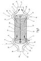
- FIG. 1 shows a heat exchanger 1 serving as a charge air cooler of a utility vehicle serves.
- the heat exchanger 1 has a first collection box 2 and a spaced second collecting box 3 for a third Fluid 4 on.
- the third fluid 4 is charge air 5.
- the charge air 5 is to be cooled by means of a fourth fluid 6.
- At the fourth fluid 6 it is cooling air 7, formed by the wind and / or by a not shown blower is baited air.
- the two collection boxes 2 and 3 are tubular, formed with an oval cross section; your Longitudinal direction is perpendicular to the plane of the figure 1.
- the heat exchanger 1 has a heat exchanger housing 8, the - in Longitudinal section of Figure 1 seen - has a bone shape. Between two thickened areas 9 and 10 of the housing 8 is a less thicker Area 11, in which the housing 8 has two planar walls 12, 13. In the thickened areas 9 and 10, the respective flat wall 12 and 13 in convex curved walls 14, 15 and 16, 17, respectively above.
- the housing 8 extends at its ends in areas 18, 19, the - in Longitudinal section of Figure 1 considered - thinner than the area 11 and respectively have a front side 20 and 21 respectively.
- the convex curved Walls 14, 15, 16 and 17 extend at a distance a to the respective Collection box 2 or 3, so that flow paths 22 to 25 are formed in the collection of the boxes 1 and 2 such that the latter can be flowed around inside the housing 8 outside.
- the thickened Areas 9 and 10, which lead to the formation of the bone form, do so possible.
- the second collection box 3 is - perpendicular to the plane of the figure 1 - the charge air 5 by means of a third, not shown, first fluid connection 26 supplied.
- the charge air 5 thus increases in the second collection box 3 and then goes 90 ° towards the first collection box 2 diverted. It happens between the two collecting tanks 3, 2 lying heat exchanger element 27. This is represented by the broken Arrow 28 indicated. After passing the heat exchanger element 27 enters the charge air 5 in the first collection box 2, is there by 90 ° deflected downwards and leaves the collection box. 2 by means of a not closer, first fluid port 29.
- the heat exchanger element 27 can be parallel to each other, the two collection boxes Be formed 2, 3 communicatively connecting charge air pipes (not shown in more detail).
- the charge air tubes are perpendicular to the longitudinal extent the headers 2 and 3. Between the individual, spaced to each other lying charge air ducts - for surface enlargement - Cooling air ribs are arranged, which are opposite to the direction the charge air 5 are flowed through by the cooling air 7, so that an intensive Heat exchange takes place in the heat exchanger element 27, the to leads that the charge air 5 is cooled by the cooling air 7.
- the Cooling air 7 by means of a second fluid connection 30, located on the front side 20 of the area 18, embedded in the interior of the housing 8, such that it passes through the two flow paths 22 and 23 and thus the second collection box 3 at least partially flows around.
- the cooling air 7 then enters the heat exchanger element 27 and flows through the countercurrent principle This component, that is, the flow direction of the Charge air 5 runs opposite to the flow direction of the cooling air. 7
- the cooling air 7 leaves the heat exchanger element 27 in the region of the second Collection box 3 and flows into the flow paths 24 and 25, the means, the collection box 3 is flowed around on both sides.
- the cooling air 7 passes then to the end face 21 of the area 19, where a second fluid port 31 to Outflow of the cooling air 7 is formed.
- the figure 1 it can be seen that the cooling air 7 no significant deflection in the region of the heat exchanger 1, in particular in the region of the heat exchanger element 27 learns.
- the flow around the two collecting tanks 2 and 3 takes place with a certain change in direction of the cooling air 7, However, which brings no significant pressure loss, since under Circumstances sets a laminar flow.
- the fluid ports 30 and 31 thus point in the direction of the flow direction of charge air. 5 inside the heat exchanger element 27.
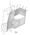
- FIG. 2 shows a plan view of a disk contour of the heat exchanger element 27, that is, the heat exchanger element 27 is in stacked disk design realized.
- individual discs profiled Aluminum sheets
- FIG. 2 shows a plan view of a disk contour of the heat exchanger element 27, that is, the heat exchanger element 27 is in stacked disk design realized.
- individual discs profiled Aluminum sheets
- FIG. 2 shows a plan view of a disk contour of the heat exchanger element 27 is in stacked disk design realized.
- individual discs profiled Aluminum sheets
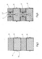
- the charge air 5 and the cooling air. 7 their respective flow paths within the heat exchanger element 27th to be able to feed, is provided according to the disc design of Figure 6, that the charge air ribs 33 there - to form the header box 2 and 3 - are connected to each other, so that the charge air. 5 the cooling air ribs 32 are separated and penetrated into the areas of the charge air ribs 33 flows in and then - almost into the leaf level of Figure 6 in - split according to the heat exchanger element 27 passes through. The same takes place in the area of the other collecting tank; there will be the Charge air brought back together and discharged together.
- the cooling air ribs 32 communicate with the flow paths 22 to 25, the means they are passed by the cooling air 5.
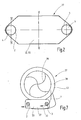
- FIG. 3 shows the housing 8, which surrounds the heat exchanger element 27, wherein the housing 8 at diametrically opposite ends of the second fluid ports 30 and 31 has. Furthermore, the fluid connections 26 and 29 visible, leading to the headers 2, 3.
- FIG. 7 shows a fan 37 with fan housing 38 and impeller 39 the fan housing 38 is a heat exchanger element 27 according to the above described embodiments integrally at least partially so recorded that guided inside the fan housing 38 cooling air. 7 the heat exchanger element 27 according to that resulting from FIG Arrows can flow through.
- the heat exchanger element 27 has due the stacking construction integrated collecting tanks 2 and 3 and intermediate Cooling air ribs 32 and charge air ribs 33, so that a guided there Charge air flow is cooled by the cooling air 7.
- the housing 38 is preferably formed as a spiral housing 40.
- FIGS. 8 and 9 schematically show a cooling system 41 and 141, respectively for an internal combustion engine 42.
- the engine 42 is powered by a coolant circuit 43 cooled, through which a liquid coolant is pumped.
- a coolant cooler 44 for a heat exchange between the coolant and cooling air 45 is arranged.
- One as a cooling fan 46th trained fluid conveyor 46 serves to promote cooling air through the coolant radiator 44.
- the arrangement of the cooling fan shown 46 - as seen in the air flow direction - after the radiator 44 is also an arrangement of the fan 46 in front of the radiator 44 possible.
- a charge air circuit 47 serves to supply combustion air to the Internal combustion engine 42, wherein the combustion air before by means of a Turbocharger 48 compressed, that is technologicallyden, and in a countercurrent heat exchanger trained intercooler 49 is cooled.
- a Turbocharger 48 compressed, that is technologically limited to a Turbocharger 48 compressed, that is technologically limited to a Turbocharger 48 compressed, that is technologically limited to a Turbocharger 48 compressed, that is technologically, and in a countercurrent heat exchanger trained intercooler 49 is cooled.
- cooling air 50 is the intercooler 49 by means of a separate, also as a fan trained fluid delivery 51 is supplied.
- the fan 51 can In this case - arranged in the air flow direction - before or after the radiator 49 be.
- a flow channel 52 on the one hand serves to guide the cooling air 50 and on the other hand, a separation of the cooling air 50 from the cooling air 45, so that a mixing of the two cooling air streams is avoidable.
- a designed as a countercurrent heat exchanger intercooler requires possibly a lower compared to a cross-flow charge air cooler Fan power, so that a less powerful and therefore smaller and / or less expensive fan for intercooler is used.
- a less powerful and therefore smaller and / or less expensive fan for intercooler is used.
- an electric fan and preferably a radial fan is suitable for this.
- the coolant cooling fan can be made smaller, because he only has the pressure drop of a heat exchanger - as opposed to two heat exchangers in the prior art - must overcome.
- the intercooler can be cooled separately from the coolant radiator, the means the intercooler is only on demand of the intercooler and the Coolant cooling fan is operated only when required by the coolant cooler. Consequently the heat exchangers are (also) adjustable via the cooling air side.
- coolant radiator - in contrast to the prior art - not with preheated cooling air of the intercooler, but with cold (Fresh) air is applied and therefore may be smaller dimensioned.
Landscapes
- Engineering & Computer Science (AREA)
- Mechanical Engineering (AREA)
- General Engineering & Computer Science (AREA)
- Physics & Mathematics (AREA)
- Thermal Sciences (AREA)
- Chemical & Material Sciences (AREA)
- Combustion & Propulsion (AREA)
- Heat-Exchange Devices With Radiators And Conduit Assemblies (AREA)
Applications Claiming Priority (2)
| Application Number | Priority Date | Filing Date | Title |
|---|---|---|---|
| DE102004001462 | 2004-01-08 | ||
| DE102004001462A DE102004001462A1 (de) | 2004-01-08 | 2004-01-08 | Kühlsystem |
Publications (3)
| Publication Number | Publication Date |
|---|---|
| EP1553273A2 true EP1553273A2 (fr) | 2005-07-13 |
| EP1553273A3 EP1553273A3 (fr) | 2011-06-15 |
| EP1553273B1 EP1553273B1 (fr) | 2017-05-17 |
Family
ID=34585373
Family Applications (1)
| Application Number | Title | Priority Date | Filing Date |
|---|---|---|---|
| EP04028830.0A Ceased EP1553273B1 (fr) | 2004-01-08 | 2004-12-06 | Système de refroidissement |
Country Status (2)
| Country | Link |
|---|---|
| EP (1) | EP1553273B1 (fr) |
| DE (1) | DE102004001462A1 (fr) |
Cited By (1)
| Publication number | Priority date | Publication date | Assignee | Title |
|---|---|---|---|---|
| WO2023088243A1 (fr) * | 2021-11-17 | 2023-05-25 | 华为技术有限公司 | Échangeur de chaleur, système de gestion thermique monté sur véhicule et véhicule électrique |
Families Citing this family (2)
| Publication number | Priority date | Publication date | Assignee | Title |
|---|---|---|---|---|
| DE102005042396A1 (de) | 2005-09-06 | 2007-03-15 | Behr Gmbh & Co. Kg | Kühlsystem für ein Kraftfahrzeug |
| DE202008011555U1 (de) * | 2008-08-28 | 2010-01-07 | Autokühler GmbH & Co. KG | Sammelkasten für einen Ladeluftkühler |
Citations (1)
| Publication number | Priority date | Publication date | Assignee | Title |
|---|---|---|---|---|
| DE10230852A1 (de) | 2002-07-04 | 2004-01-22 | Behr Gmbh & Co. | Wärmetauscher, insbesondere Ladeluftkühler für Kraftfahrzeuge |
Family Cites Families (11)
| Publication number | Priority date | Publication date | Assignee | Title |
|---|---|---|---|---|
| US3203499A (en) * | 1962-06-08 | 1965-08-31 | Caterpillar Tractor Co | Cooling arrangement for supercharged engines |
| DE3320754A1 (de) * | 1983-06-09 | 1984-02-16 | Büro Mergenthaler Wirtschaftsberatung, 8000 München | Ladeluftkuehlung fuer abgasturbolader |
| FR2614406B1 (fr) * | 1987-04-27 | 1989-12-08 | Valeo | Echangeur de chaleur a deux etages et son procede de montage |
| SU1571282A1 (ru) * | 1987-12-04 | 1990-06-15 | Производственное Объединение "Камский Тракторный Завод" | Система охлаждени силовой установки с двигателем внутреннего сгорани |
| US5209285A (en) * | 1990-09-24 | 1993-05-11 | General Motors Corporation | Inclined tube radiator |
| JP3852255B2 (ja) * | 1999-11-10 | 2006-11-29 | いすゞ自動車株式会社 | Egr及びオイルの冷却装置 |
| GB2375388A (en) * | 2001-05-10 | 2002-11-13 | Llanelli Radiators Ltd | Heat exchanger arrangement for charge air |
| FI116802B (fi) * | 2002-01-17 | 2006-02-28 | Waertsilae Finland Oy | Mäntämoottorin imuilmajärjestely |
| FR2835884B1 (fr) * | 2002-02-12 | 2005-03-18 | Valeo Thermique Moteur Sa | Procede de controle de la temperature de gaz admis dans un moteur de vehicule automobile, echangeur et dispositif de gestion de la temperature de ces gaz |
| ATE469292T1 (de) * | 2002-03-08 | 2010-06-15 | Behr Gmbh & Co Kg | Vorrichtung zur kühlung von ladeluft und verfahren zum betreiben einer derartigen vorrichtung |
| FR2840363B1 (fr) * | 2002-06-04 | 2006-01-06 | Valeo Thermique Moteur Sa | Module d'echange de chaleur conforme pour envelopper un moteur de vehicule automobile |
-
2004
- 2004-01-08 DE DE102004001462A patent/DE102004001462A1/de not_active Withdrawn
- 2004-12-06 EP EP04028830.0A patent/EP1553273B1/fr not_active Ceased
Patent Citations (1)
| Publication number | Priority date | Publication date | Assignee | Title |
|---|---|---|---|---|
| DE10230852A1 (de) | 2002-07-04 | 2004-01-22 | Behr Gmbh & Co. | Wärmetauscher, insbesondere Ladeluftkühler für Kraftfahrzeuge |
Cited By (1)
| Publication number | Priority date | Publication date | Assignee | Title |
|---|---|---|---|---|
| WO2023088243A1 (fr) * | 2021-11-17 | 2023-05-25 | 华为技术有限公司 | Échangeur de chaleur, système de gestion thermique monté sur véhicule et véhicule électrique |
Also Published As
| Publication number | Publication date |
|---|---|
| DE102004001462A1 (de) | 2005-08-18 |
| EP1553273A3 (fr) | 2011-06-15 |
| EP1553273B1 (fr) | 2017-05-17 |
Similar Documents
| Publication | Publication Date | Title |
|---|---|---|
| DE102012006346B4 (de) | Wärmetauscher | |
| EP1682840B1 (fr) | Echangeur de chaleur, en particulier pour vehicules automobiles | |
| DE19536116B4 (de) | Wärmeübertrager für ein Kraftfahrzeug | |
| EP2021717B1 (fr) | Échangeur thermique pour vehicules automobiles | |
| EP3119623A1 (fr) | Module de chauffage et de refroidissement | |
| DE102018200809A1 (de) | Stapelscheibenwärmetauscher | |
| DE10328638A1 (de) | Wärmetauscher in gehäuseloser Plattenbauweise | |
| DE102013002545A1 (de) | Kondensator mit einem Stapel aus Wärmetauscherplatten | |
| DE102015220965A1 (de) | Indirekter Ladeluftkühler | |
| DE102008017113A1 (de) | Verdampfer | |
| WO2023020855A1 (fr) | Ensemble modulaire pour un circuit de fluide frigorigène d'un véhicule à moteur, et circuit de fluide frigorigène | |
| DE102007013125A1 (de) | Wärmeübertrager | |
| EP1956212A1 (fr) | Agencement d'un refroidisseur d'air de suralimentation dans un système d'aspiration d'un moteur à combustion interne | |
| DE4330214B4 (de) | Wärmetauscher | |
| EP1842019B1 (fr) | Evaporateur destine notamment au systeme de climatisation d'un vehicule automobile | |
| EP2107328B1 (fr) | Evaporateur | |
| EP1553273A2 (fr) | Système de refroidissement | |
| DE112017001679B4 (de) | Ladeluftkühler | |
| DE102021213376A1 (de) | Wärmeübertrager und Kältemittelkreislauf mit einem Wärmeübertrager | |
| EP1521940B1 (fr) | Echangeur thermique, notamment echangeur air/air destine a des vehicules | |
| DE102006061440A1 (de) | Kühlflüssigkeitskühler | |
| DE202017103235U1 (de) | Wärmeaustauscher | |
| DE102009013677B4 (de) | Verfahren zum Bauen von Ladeluftkühlervorrichtungen in Kraftwagen | |
| DE102006017610B4 (de) | Wärmetauscher zur Ladeluftkühlung für Kraftfahrzeuge, System | |
| DE102021208924A1 (de) | Wärmeübertrager |
Legal Events
| Date | Code | Title | Description |
|---|---|---|---|
| PUAI | Public reference made under article 153(3) epc to a published international application that has entered the european phase |
Free format text: ORIGINAL CODE: 0009012 |
|
| AK | Designated contracting states |
Kind code of ref document: A2 Designated state(s): AT BE BG CH CY CZ DE DK EE ES FI FR GB GR HU IE IS IT LI LT LU MC NL PL PT RO SE SI SK TR |
|
| AX | Request for extension of the european patent |
Extension state: AL BA HR LV MK YU |
|
| PUAL | Search report despatched |
Free format text: ORIGINAL CODE: 0009013 |
|
| AK | Designated contracting states |
Kind code of ref document: A3 Designated state(s): AT BE BG CH CY CZ DE DK EE ES FI FR GB GR HU IE IS IT LI LT LU MC NL PL PT RO SE SI SK TR |
|
| AX | Request for extension of the european patent |
Extension state: AL BA HR LV MK YU |
|
| RIC1 | Information provided on ipc code assigned before grant |
Ipc: F02B 29/04 20060101AFI20050317BHEP Ipc: F02M 25/07 20060101ALI20110509BHEP |
|
| 17P | Request for examination filed |
Effective date: 20111215 |
|
| AKX | Designation fees paid |
Designated state(s): DE FR GB |
|
| 17Q | First examination report despatched |
Effective date: 20120809 |
|
| RAP1 | Party data changed (applicant data changed or rights of an application transferred) |
Owner name: MAHLE BEHR GMBH & CO. KG |
|
| REG | Reference to a national code |
Ref country code: DE Ref legal event code: R079 Ref document number: 502004015532 Country of ref document: DE Free format text: PREVIOUS MAIN CLASS: F02B0029040000 Ipc: F02M0026240000 |
|
| RIC1 | Information provided on ipc code assigned before grant |
Ipc: F02M 26/24 20160101AFI20160930BHEP |
|
| GRAP | Despatch of communication of intention to grant a patent |
Free format text: ORIGINAL CODE: EPIDOSNIGR1 |
|
| INTG | Intention to grant announced |
Effective date: 20161213 |
|
| GRAS | Grant fee paid |
Free format text: ORIGINAL CODE: EPIDOSNIGR3 |
|
| GRAJ | Information related to disapproval of communication of intention to grant by the applicant or resumption of examination proceedings by the epo deleted |
Free format text: ORIGINAL CODE: EPIDOSDIGR1 |
|
| GRAL | Information related to payment of fee for publishing/printing deleted |
Free format text: ORIGINAL CODE: EPIDOSDIGR3 |
|
| GRAR | Information related to intention to grant a patent recorded |
Free format text: ORIGINAL CODE: EPIDOSNIGR71 |
|
| GRAA | (expected) grant |
Free format text: ORIGINAL CODE: 0009210 |
|
| INTC | Intention to grant announced (deleted) | ||
| RIN1 | Information on inventor provided before grant (corrected) |
Inventor name: KULL, REINHARD Inventor name: EMRICH, KARSTEN, DIPL.-ING. Inventor name: SCHAIRER, ANDRE, DIPL.-ING. (FH) |
|
| AK | Designated contracting states |
Kind code of ref document: B1 Designated state(s): DE FR GB |
|
| INTG | Intention to grant announced |
Effective date: 20170410 |
|
| REG | Reference to a national code |
Ref country code: GB Ref legal event code: FG4D Free format text: NOT ENGLISH |
|
| REG | Reference to a national code |
Ref country code: DE Ref legal event code: R096 Ref document number: 502004015532 Country of ref document: DE |
|
| REG | Reference to a national code |
Ref country code: FR Ref legal event code: PLFP Year of fee payment: 14 |
|
| REG | Reference to a national code |
Ref country code: DE Ref legal event code: R097 Ref document number: 502004015532 Country of ref document: DE |
|
| PLBE | No opposition filed within time limit |
Free format text: ORIGINAL CODE: 0009261 |
|
| STAA | Information on the status of an ep patent application or granted ep patent |
Free format text: STATUS: NO OPPOSITION FILED WITHIN TIME LIMIT |
|
| 26N | No opposition filed |
Effective date: 20180220 |
|
| GBPC | Gb: european patent ceased through non-payment of renewal fee |
Effective date: 20171206 |
|
| PG25 | Lapsed in a contracting state [announced via postgrant information from national office to epo] |
Ref country code: GB Free format text: LAPSE BECAUSE OF NON-PAYMENT OF DUE FEES Effective date: 20171206 |
|
| PGFP | Annual fee paid to national office [announced via postgrant information from national office to epo] |
Ref country code: FR Payment date: 20181221 Year of fee payment: 15 |
|
| PGFP | Annual fee paid to national office [announced via postgrant information from national office to epo] |
Ref country code: DE Payment date: 20190109 Year of fee payment: 15 |
|
| REG | Reference to a national code |
Ref country code: DE Ref legal event code: R119 Ref document number: 502004015532 Country of ref document: DE |
|
| PG25 | Lapsed in a contracting state [announced via postgrant information from national office to epo] |
Ref country code: FR Free format text: LAPSE BECAUSE OF NON-PAYMENT OF DUE FEES Effective date: 20191231 Ref country code: DE Free format text: LAPSE BECAUSE OF NON-PAYMENT OF DUE FEES Effective date: 20200701 |