EP1553273A2 - Cooling system - Google Patents
Cooling system Download PDFInfo
- Publication number
- EP1553273A2 EP1553273A2 EP04028830A EP04028830A EP1553273A2 EP 1553273 A2 EP1553273 A2 EP 1553273A2 EP 04028830 A EP04028830 A EP 04028830A EP 04028830 A EP04028830 A EP 04028830A EP 1553273 A2 EP1553273 A2 EP 1553273A2
- Authority
- EP
- European Patent Office
- Prior art keywords
- fluid
- heat exchanger
- cooling system
- housing
- cooling
- Prior art date
- Legal status (The legal status is an assumption and is not a legal conclusion. Google has not performed a legal analysis and makes no representation as to the accuracy of the status listed.)
- Granted
Links
- 238000001816 cooling Methods 0.000 title claims abstract description 86
- 239000012530 fluid Substances 0.000 claims abstract description 84
- 238000002485 combustion reaction Methods 0.000 claims abstract description 21
- 239000007788 liquid Substances 0.000 claims abstract description 5
- 239000012809 cooling fluid Substances 0.000 claims description 10
- 238000000926 separation method Methods 0.000 claims description 3
- 239000003570 air Substances 0.000 description 87
- 239000002826 coolant Substances 0.000 description 12
- 230000015572 biosynthetic process Effects 0.000 description 4
- 210000000988 bone and bone Anatomy 0.000 description 3
- XAGFODPZIPBFFR-UHFFFAOYSA-N aluminium Chemical compound [Al] XAGFODPZIPBFFR-UHFFFAOYSA-N 0.000 description 1
- 229910052782 aluminium Inorganic materials 0.000 description 1
- 239000012080 ambient air Substances 0.000 description 1
- 238000010276 construction Methods 0.000 description 1
- 238000010438 heat treatment Methods 0.000 description 1
- 238000004519 manufacturing process Methods 0.000 description 1
- 238000005192 partition Methods 0.000 description 1
- 238000005496 tempering Methods 0.000 description 1
Images


Classifications
-
- F—MECHANICAL ENGINEERING; LIGHTING; HEATING; WEAPONS; BLASTING
- F28—HEAT EXCHANGE IN GENERAL
- F28D—HEAT-EXCHANGE APPARATUS, NOT PROVIDED FOR IN ANOTHER SUBCLASS, IN WHICH THE HEAT-EXCHANGE MEDIA DO NOT COME INTO DIRECT CONTACT
- F28D9/00—Heat-exchange apparatus having stationary plate-like or laminated conduit assemblies for both heat-exchange media, the media being in contact with different sides of a conduit wall
- F28D9/0031—Heat-exchange apparatus having stationary plate-like or laminated conduit assemblies for both heat-exchange media, the media being in contact with different sides of a conduit wall the conduits for one heat-exchange medium being formed by paired plates touching each other
- F28D9/0043—Heat-exchange apparatus having stationary plate-like or laminated conduit assemblies for both heat-exchange media, the media being in contact with different sides of a conduit wall the conduits for one heat-exchange medium being formed by paired plates touching each other the plates having openings therein for circulation of at least one heat-exchange medium from one conduit to another
-
- F—MECHANICAL ENGINEERING; LIGHTING; HEATING; WEAPONS; BLASTING
- F02—COMBUSTION ENGINES; HOT-GAS OR COMBUSTION-PRODUCT ENGINE PLANTS
- F02B—INTERNAL-COMBUSTION PISTON ENGINES; COMBUSTION ENGINES IN GENERAL
- F02B29/00—Engines characterised by provision for charging or scavenging not provided for in groups F02B25/00, F02B27/00 or F02B33/00 - F02B39/00; Details thereof
- F02B29/04—Cooling of air intake supply
- F02B29/0406—Layout of the intake air cooling or coolant circuit
- F02B29/0412—Multiple heat exchangers arranged in parallel or in series
-
- F—MECHANICAL ENGINEERING; LIGHTING; HEATING; WEAPONS; BLASTING
- F02—COMBUSTION ENGINES; HOT-GAS OR COMBUSTION-PRODUCT ENGINE PLANTS
- F02M—SUPPLYING COMBUSTION ENGINES IN GENERAL WITH COMBUSTIBLE MIXTURES OR CONSTITUENTS THEREOF
- F02M26/00—Engine-pertinent apparatus for adding exhaust gases to combustion-air, main fuel or fuel-air mixture, e.g. by exhaust gas recirculation [EGR] systems
- F02M26/13—Arrangement or layout of EGR passages, e.g. in relation to specific engine parts or for incorporation of accessories
- F02M26/22—Arrangement or layout of EGR passages, e.g. in relation to specific engine parts or for incorporation of accessories with coolers in the recirculation passage
- F02M26/23—Layout, e.g. schematics
- F02M26/24—Layout, e.g. schematics with two or more coolers
-
- F—MECHANICAL ENGINEERING; LIGHTING; HEATING; WEAPONS; BLASTING
- F28—HEAT EXCHANGE IN GENERAL
- F28F—DETAILS OF HEAT-EXCHANGE AND HEAT-TRANSFER APPARATUS, OF GENERAL APPLICATION
- F28F2250/00—Arrangements for modifying the flow of the heat exchange media, e.g. flow guiding means; Particular flow patterns
- F28F2250/10—Particular pattern of flow of the heat exchange media
- F28F2250/104—Particular pattern of flow of the heat exchange media with parallel flow
-
- Y—GENERAL TAGGING OF NEW TECHNOLOGICAL DEVELOPMENTS; GENERAL TAGGING OF CROSS-SECTIONAL TECHNOLOGIES SPANNING OVER SEVERAL SECTIONS OF THE IPC; TECHNICAL SUBJECTS COVERED BY FORMER USPC CROSS-REFERENCE ART COLLECTIONS [XRACs] AND DIGESTS
- Y02—TECHNOLOGIES OR APPLICATIONS FOR MITIGATION OR ADAPTATION AGAINST CLIMATE CHANGE
- Y02T—CLIMATE CHANGE MITIGATION TECHNOLOGIES RELATED TO TRANSPORTATION
- Y02T10/00—Road transport of goods or passengers
- Y02T10/10—Internal combustion engine [ICE] based vehicles
- Y02T10/12—Improving ICE efficiencies
Definitions
- the invention relates to a cooling system for an internal combustion engine, in particular for a motor vehicle, with several circuits with heat exchangers for several fluids.
- Such cooling systems are used for example in motor vehicles for cooling a cooling fluid of an internal combustion engine and for cooling combustion air, which is compressed in particular with a turbocharger.
- charge air becomes like the cooling fluid of the internal combustion engine frequently cooled by means of cooling air, wherein as cooling air of the wind of the Vehicle or conveyed by a fan ambient air is used.
- Two headers of a known heat exchanger for example connected via charge air or coolant pipes, wherein -zur Surface enlargement- arranged between the tubes cooling fins are. These cooling fins are flowed through by the cooling air.
- a cooling fluid through several in the flow direction of the Cooling fluids passed successively arranged heat exchanger, so that several Fluids can be cooled by means of the cooling fluid.
- This is just a flow guide and optionally only a conveying device for the cooling fluid, such as a cooling fan, necessary for several heat exchangers.
- the heat exchangers are often designed as a cross-flow heat exchanger.
- a disadvantage of such an arrangement is a heating of the Cooling air in a first heat exchanger, so that in all other heat exchangers a temperature difference between heat exchanging fluids and thus the efficiency of the heat exchangers is reduced.
- the cooling fluid must always against the flow resistance of all Heat exchangers are promoted, even in operating conditions of the cooling system, in which not all heat exchangers necessarily with cooling air need to be supplied.
- An object of the invention is in particular, a cooling system of the beginning to provide such a type in which an independent supply of several Heat exchanger is made possible with a fluid.
- a basic idea of the invention is a first heat exchanger of a first circuit, a first fluid conveyor and a second heat exchanger Assign a second fluid delivery device of a second circuit.
- a heat exchange between a first and a second fluid by means of the first Heat exchanger regardless of a heat exchange between a third and a fourth fluid influenced by the second heat exchanger, by the first fluid conveying device independent of the second Fluid conveyor is operated.
- the first fluid conveying device independent of the second Fluid conveyor
- a separating element for a Separation of the second provided by the fourth fluid This will be a Mixing the second avoided with the fourth fluid.
- the separating element is in particular as a partition, as a fluid guide element or Baffle or as a flow channel for the second and / or the fourth fluid educated.
- the first and / or the second heat exchanger designed as a cross-flow heat exchanger. This is Under certain circumstances, easy accessibility for the fluids involved the relevant heat exchanger possible.
- the first and / or the second heat exchanger designed as a counter or DC heat exchanger.
- the first and / or the second heat exchanger according to the German application with the file number 102 30 852.7, whose Content hereby expressly belongs to the disclosure content.
- the first and / or the second fluid delivery device designed as a fan. This may be Cooling air through the / the heat exchanger can be conveyed.
- the first and / or the second fluid delivery device comprises a fluid delivery device housing.
- a guide of the respective fluid is possible.
- the fluid conveyor housing is advantageously as a flow channel or formed as a spiral housing.
- Formation of the fluid conveyor housing with a housing the first or second heat exchanger is under circumstances a production cost of the cooling system according to the invention can be reduced.
- the first and / or the third fluid liquid are suitable for heat transport.
- the first fluid is a cooling fluid for cooling the internal combustion engine.
- Cooling fluid optionally excess heat from the engine transportable to the first heat exchanger and to the second fluid dispensable.
- the third fluid is combustion air for the internal combustion engine.
- the combustion air before flowing through the second heat exchanger by means of a Air conveyor charged By tempering and / or charging The combustion air may be an efficiency of the internal combustion engine be increased.
- the second and / or the fourth fluid gaseous.
- the second and / or the fourth fluid Cooling air may be available in large quantities and is suitable for the removal of excess heat.
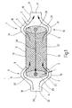
- FIG. 1 shows a heat exchanger 1 serving as a charge air cooler of a utility vehicle serves.
- the heat exchanger 1 has a first collection box 2 and a spaced second collecting box 3 for a third Fluid 4 on.
- the third fluid 4 is charge air 5.
- the charge air 5 is to be cooled by means of a fourth fluid 6.
- At the fourth fluid 6 it is cooling air 7, formed by the wind and / or by a not shown blower is baited air.
- the two collection boxes 2 and 3 are tubular, formed with an oval cross section; your Longitudinal direction is perpendicular to the plane of the figure 1.
- the heat exchanger 1 has a heat exchanger housing 8, the - in Longitudinal section of Figure 1 seen - has a bone shape. Between two thickened areas 9 and 10 of the housing 8 is a less thicker Area 11, in which the housing 8 has two planar walls 12, 13. In the thickened areas 9 and 10, the respective flat wall 12 and 13 in convex curved walls 14, 15 and 16, 17, respectively above.
- the housing 8 extends at its ends in areas 18, 19, the - in Longitudinal section of Figure 1 considered - thinner than the area 11 and respectively have a front side 20 and 21 respectively.
- the convex curved Walls 14, 15, 16 and 17 extend at a distance a to the respective Collection box 2 or 3, so that flow paths 22 to 25 are formed in the collection of the boxes 1 and 2 such that the latter can be flowed around inside the housing 8 outside.
- the thickened Areas 9 and 10, which lead to the formation of the bone form, do so possible.
- the second collection box 3 is - perpendicular to the plane of the figure 1 - the charge air 5 by means of a third, not shown, first fluid connection 26 supplied.
- the charge air 5 thus increases in the second collection box 3 and then goes 90 ° towards the first collection box 2 diverted. It happens between the two collecting tanks 3, 2 lying heat exchanger element 27. This is represented by the broken Arrow 28 indicated. After passing the heat exchanger element 27 enters the charge air 5 in the first collection box 2, is there by 90 ° deflected downwards and leaves the collection box. 2 by means of a not closer, first fluid port 29.
- the heat exchanger element 27 can be parallel to each other, the two collection boxes Be formed 2, 3 communicatively connecting charge air pipes (not shown in more detail).
- the charge air tubes are perpendicular to the longitudinal extent the headers 2 and 3. Between the individual, spaced to each other lying charge air ducts - for surface enlargement - Cooling air ribs are arranged, which are opposite to the direction the charge air 5 are flowed through by the cooling air 7, so that an intensive Heat exchange takes place in the heat exchanger element 27, the to leads that the charge air 5 is cooled by the cooling air 7.
- the Cooling air 7 by means of a second fluid connection 30, located on the front side 20 of the area 18, embedded in the interior of the housing 8, such that it passes through the two flow paths 22 and 23 and thus the second collection box 3 at least partially flows around.
- the cooling air 7 then enters the heat exchanger element 27 and flows through the countercurrent principle This component, that is, the flow direction of the Charge air 5 runs opposite to the flow direction of the cooling air. 7
- the cooling air 7 leaves the heat exchanger element 27 in the region of the second Collection box 3 and flows into the flow paths 24 and 25, the means, the collection box 3 is flowed around on both sides.
- the cooling air 7 passes then to the end face 21 of the area 19, where a second fluid port 31 to Outflow of the cooling air 7 is formed.
- the figure 1 it can be seen that the cooling air 7 no significant deflection in the region of the heat exchanger 1, in particular in the region of the heat exchanger element 27 learns.
- the flow around the two collecting tanks 2 and 3 takes place with a certain change in direction of the cooling air 7, However, which brings no significant pressure loss, since under Circumstances sets a laminar flow.
- the fluid ports 30 and 31 thus point in the direction of the flow direction of charge air. 5 inside the heat exchanger element 27.
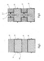
- FIG. 2 shows a plan view of a disk contour of the heat exchanger element 27, that is, the heat exchanger element 27 is in stacked disk design realized.
- individual discs profiled Aluminum sheets
- FIG. 2 shows a plan view of a disk contour of the heat exchanger element 27, that is, the heat exchanger element 27 is in stacked disk design realized.
- individual discs profiled Aluminum sheets
- FIG. 2 shows a plan view of a disk contour of the heat exchanger element 27 is in stacked disk design realized.
- individual discs profiled Aluminum sheets
- the charge air 5 and the cooling air. 7 their respective flow paths within the heat exchanger element 27th to be able to feed, is provided according to the disc design of Figure 6, that the charge air ribs 33 there - to form the header box 2 and 3 - are connected to each other, so that the charge air. 5 the cooling air ribs 32 are separated and penetrated into the areas of the charge air ribs 33 flows in and then - almost into the leaf level of Figure 6 in - split according to the heat exchanger element 27 passes through. The same takes place in the area of the other collecting tank; there will be the Charge air brought back together and discharged together.
- the cooling air ribs 32 communicate with the flow paths 22 to 25, the means they are passed by the cooling air 5.
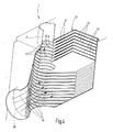
- FIG. 3 shows the housing 8, which surrounds the heat exchanger element 27, wherein the housing 8 at diametrically opposite ends of the second fluid ports 30 and 31 has. Furthermore, the fluid connections 26 and 29 visible, leading to the headers 2, 3.
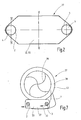
- FIG. 7 shows a fan 37 with fan housing 38 and impeller 39 the fan housing 38 is a heat exchanger element 27 according to the above described embodiments integrally at least partially so recorded that guided inside the fan housing 38 cooling air. 7 the heat exchanger element 27 according to that resulting from FIG Arrows can flow through.
- the heat exchanger element 27 has due the stacking construction integrated collecting tanks 2 and 3 and intermediate Cooling air ribs 32 and charge air ribs 33, so that a guided there Charge air flow is cooled by the cooling air 7.
- the housing 38 is preferably formed as a spiral housing 40.
- FIGS. 8 and 9 schematically show a cooling system 41 and 141, respectively for an internal combustion engine 42.
- the engine 42 is powered by a coolant circuit 43 cooled, through which a liquid coolant is pumped.
- a coolant cooler 44 for a heat exchange between the coolant and cooling air 45 is arranged.
- One as a cooling fan 46th trained fluid conveyor 46 serves to promote cooling air through the coolant radiator 44.
- the arrangement of the cooling fan shown 46 - as seen in the air flow direction - after the radiator 44 is also an arrangement of the fan 46 in front of the radiator 44 possible.
- a charge air circuit 47 serves to supply combustion air to the Internal combustion engine 42, wherein the combustion air before by means of a Turbocharger 48 compressed, that is technologicallyden, and in a countercurrent heat exchanger trained intercooler 49 is cooled.
- a Turbocharger 48 compressed, that is technologically limited to a Turbocharger 48 compressed, that is technologically limited to a Turbocharger 48 compressed, that is technologically limited to a Turbocharger 48 compressed, that is technologically, and in a countercurrent heat exchanger trained intercooler 49 is cooled.
- cooling air 50 is the intercooler 49 by means of a separate, also as a fan trained fluid delivery 51 is supplied.
- the fan 51 can In this case - arranged in the air flow direction - before or after the radiator 49 be.
- a flow channel 52 on the one hand serves to guide the cooling air 50 and on the other hand, a separation of the cooling air 50 from the cooling air 45, so that a mixing of the two cooling air streams is avoidable.
- a designed as a countercurrent heat exchanger intercooler requires possibly a lower compared to a cross-flow charge air cooler Fan power, so that a less powerful and therefore smaller and / or less expensive fan for intercooler is used.
- a less powerful and therefore smaller and / or less expensive fan for intercooler is used.
- an electric fan and preferably a radial fan is suitable for this.
- the coolant cooling fan can be made smaller, because he only has the pressure drop of a heat exchanger - as opposed to two heat exchangers in the prior art - must overcome.
- the intercooler can be cooled separately from the coolant radiator, the means the intercooler is only on demand of the intercooler and the Coolant cooling fan is operated only when required by the coolant cooler. Consequently the heat exchangers are (also) adjustable via the cooling air side.
- coolant radiator - in contrast to the prior art - not with preheated cooling air of the intercooler, but with cold (Fresh) air is applied and therefore may be smaller dimensioned.
Landscapes
- Engineering & Computer Science (AREA)
- Mechanical Engineering (AREA)
- General Engineering & Computer Science (AREA)
- Physics & Mathematics (AREA)
- Thermal Sciences (AREA)
- Chemical & Material Sciences (AREA)
- Combustion & Propulsion (AREA)
- Heat-Exchange Devices With Radiators And Conduit Assemblies (AREA)
Abstract
Description
Die Erfindung betrifft ein Kühlsystem für einen Verbrennungsmotor, insbesondere für ein Kraftfahrzeug, mit mehreren Kreisläufen mit Wärmeübertragern für mehrere Fluide.The invention relates to a cooling system for an internal combustion engine, in particular for a motor vehicle, with several circuits with heat exchangers for several fluids.
Derartige Kühlsysteme dienen beispielsweise in Kraftfahrzeugen zur Kühlung eines Kühlfluids eines Verbrennungsmotors und zur Kühlung von Verbrennungsluft, die insbesondere mit einem Turbolader komprimiert wird. Solchermaßen aufgeladene Ladeluft wird wie das Kühlfluid des Verbrennungsmotors häufig mittels Kühlluft abgekühlt, wobei als Kühlluft der Fahrtwind des Fahrzeugs oder von einem Lüfter geförderte Umgebungsluft eingesetzt wird. Zwei Sammelkästen eines bekannten Wärmetauschers sind beispielsweise über Ladeluft- oder Kühlmittelrohre miteinander verbunden, wobei -zur Oberflächenvergrößerung- zwischen den Rohren Kühlrippen angeordnet sind. Diese Kühlrippen werden von der Kühlluft durchströmt.Such cooling systems are used for example in motor vehicles for cooling a cooling fluid of an internal combustion engine and for cooling combustion air, which is compressed in particular with a turbocharger. thus charged charge air becomes like the cooling fluid of the internal combustion engine frequently cooled by means of cooling air, wherein as cooling air of the wind of the Vehicle or conveyed by a fan ambient air is used. Two headers of a known heat exchanger, for example connected via charge air or coolant pipes, wherein -zur Surface enlargement- arranged between the tubes cooling fins are. These cooling fins are flowed through by the cooling air.
Üblicherweise wird ein Kühlfluid durch mehrere in Strömungsrichtung des Kühlfluids hintereinander angeordnete Wärmetauscher geleitet, so daß mehrere Fluide mittels des Kühlfluids abkühlbar sind. Dadurch ist nur eine Strömungsführung und gegebenenfalls nur eine Fördereinrichtung für das Kühlfluid, wie beispielsweise ein Kühllüfter, für mehrere Wärmetauscher notwendig. Die Wärmetauscher sind dabei oft als Kreuzstromwärmetauscher ausgebildet. Ein Nachteil an einer solchen Anordnung ist eine Erwärmung der Kühlluft in einem ersten Wärmetauscher, so daß in allen weiteren Wärmetauschem ein Temperaturunterschied zwischen wärmeaustauschenden Fluiden und damit die Leistungsfähigkeit der Wärmetauscher reduziert ist. Außerdem muß das Kühlfluid immer gegen den Strömungswiderstand aller Wärmetauscher gefördert werden, auch in Betriebszuständen des Kühlsystems, in denen nicht alle Wärmetauscher notwendigerweise mit Kühlluft versorgt werden müssen.Usually, a cooling fluid through several in the flow direction of the Cooling fluids passed successively arranged heat exchanger, so that several Fluids can be cooled by means of the cooling fluid. This is just a flow guide and optionally only a conveying device for the cooling fluid, such as a cooling fan, necessary for several heat exchangers. The heat exchangers are often designed as a cross-flow heat exchanger. A disadvantage of such an arrangement is a heating of the Cooling air in a first heat exchanger, so that in all other heat exchangers a temperature difference between heat exchanging fluids and thus the efficiency of the heat exchangers is reduced. Furthermore the cooling fluid must always against the flow resistance of all Heat exchangers are promoted, even in operating conditions of the cooling system, in which not all heat exchangers necessarily with cooling air need to be supplied.
Eine Aufgabe der Erfindung ist insbesondere, ein Kühlsystem der eingangs genannten Art bereitzustellen, bei dem eine unabhängige Versorgung mehrerer Wärmeübertrager mit einem Fluid ermöglicht wird.An object of the invention is in particular, a cooling system of the beginning to provide such a type in which an independent supply of several Heat exchanger is made possible with a fluid.
Ein Grundgedanke der Erfindung ist es, einem ersten Wärmetauscher eines ersten Kreislaufs eine erste Fluidfördereinrichtung und einem zweiten Wärmetauscher eines zweiten Kreislaufs eine zweite Fluidfördereinrichtung zuzuordnen.A basic idea of the invention is a first heat exchanger of a first circuit, a first fluid conveyor and a second heat exchanger Assign a second fluid delivery device of a second circuit.
Insbesondere ist bei einem erfindungsgemäßen Kühlsystem ein Wärmetausch zwischen einem ersten und einem zweiten Fluid mittels des ersten Wärmetauschers unabhängig von einem Wärmetausch zwischen einem dritten und einem vierten Fluid mittels des zweiten Wärmetauschers beeinflußbar, indem die erste Fluidfördereinrichtung unabhängig von der zweiten Fluidfördereinrichtung betrieben wird. Beispielsweise ist es möglich, daß in bestimmten Betriebszuständen des Kühlsystems jeweils nur eine Fluidfördereinrichtung betrieben wird. Dadurch ist überflüssiger Energieverbrauch für die Fluidförderung reduzierbar oder vermeidbar.In particular, in a cooling system according to the invention, a heat exchange between a first and a second fluid by means of the first Heat exchanger regardless of a heat exchange between a third and a fourth fluid influenced by the second heat exchanger, by the first fluid conveying device independent of the second Fluid conveyor is operated. For example, it is possible that in certain operating conditions of the cooling system only one fluid conveyor is operated. This is unnecessary power consumption for the fluid delivery reducible or avoidable.
Gemäß einer Ausführungsform der Erfindung ist ein Trennelement für eine Trennung des zweiten von dem vierten Fluid vorgesehen. Damit wird eine Vermischung des zweiten mit dem vierten Fluid vermieden. Das Trennelement ist dabei insbesondere als Trennwand, als Fluidführungselement oder Leitblech oder als Strömungskanal für das zweite und/oder das vierte Fluid ausgebildet.According to one embodiment of the invention, a separating element for a Separation of the second provided by the fourth fluid. This will be a Mixing the second avoided with the fourth fluid. The separating element is in particular as a partition, as a fluid guide element or Baffle or as a flow channel for the second and / or the fourth fluid educated.
Gemäß einer Ausführungsform der Erfindung ist der erste und/oder der zweite Wärmetauscher als Kreuzstromwärmetauscher ausgebildet. Damit ist unter Umständen eine leichte Zugänglichkeit für die beteiligten Fluide zu dem betreffenden Wärmetauscher möglich.According to one embodiment of the invention, the first and / or the second heat exchanger designed as a cross-flow heat exchanger. This is Under certain circumstances, easy accessibility for the fluids involved the relevant heat exchanger possible.
Gemäß einer Ausführungsform der Erfindung ist der erste und/oder der zweite Wärmetauscher als Gegen- oder Gleichstromwärmetauscher ausgebildet. Dadurch wird unter Umständen eine von der jeweiligen Fluidfördereinrichtung aufzubringende Förderleistung verringert, so daß die Fluidfördereinrichtung kleiner und/oder kostengünstiger fertigbar ist.According to one embodiment of the invention, the first and / or the second heat exchanger designed as a counter or DC heat exchanger. As a result, under certain circumstances, one of the respective fluid conveyor applied delivery rate reduced, so that the fluid delivery device smaller and / or less expensive manufacturable.
Insbesondere ist der erste und/oder der zweite Wärmetauscher gemäß der deutschen Anmeldung mit dem Aktenzeichen 102 30 852.7 ausgebildet, deren Inhalt hiermit ausdrücklich zum Offenbarungsgehalt gehört.In particular, the first and / or the second heat exchanger according to the German application with the file number 102 30 852.7, whose Content hereby expressly belongs to the disclosure content.
Gemäß einer Ausführungsform der Erfindung ist die erste und/oder die zweite Fluidfördereinrichtung als Lüfter ausgebildet. Damit ist unter Umständen Kühlluft durch den/die Wärmetauscher förderbar.According to one embodiment of the invention, the first and / or the second fluid delivery device designed as a fan. This may be Cooling air through the / the heat exchanger can be conveyed.
Gemäß einer Ausführungsform der Erfindung weist die erste und/oder die zweite Fluidfördereinrichtung ein Fluidfördereinrichtungsgehäuse auf. Damit ist unter Umständen eine Führung des jeweiligen Fluids möglich. Das Fluidfördereinrichtungsgehäuse ist dabei vorteilhafterweise als Strömungskanal oder als Spiralgehäuse ausgebildet. Bei einer einteiligen, vorzugsweise einstückigen Ausbildung des Fluidfördereinrichtungsgehäuses mit einem Gehäuse des ersten beziehungsweise zweiten Wärmetauschers ist unter Umständen ein Fertigungsaufwand des erfindungsgemäßen Kühlsystems reduzierbar.According to one embodiment of the invention, the first and / or the second fluid delivery device comprises a fluid delivery device housing. In order to Under certain circumstances, a guide of the respective fluid is possible. The fluid conveyor housing is advantageously as a flow channel or formed as a spiral housing. In a one-piece, preferably one-piece Formation of the fluid conveyor housing with a housing the first or second heat exchanger is under circumstances a production cost of the cooling system according to the invention can be reduced.
Gemäß einer Ausführungsform der Erfindung ist das erste und/oder das dritte Fluid flüssig. Flüssigkeiten haben oft einen hohen Wärmekoeffizienten und eignen sich für einen Wärmetransport.According to one embodiment of the invention, the first and / or the third fluid liquid. Liquids often have a high thermal coefficient and are suitable for heat transport.
Gemäß einer Ausführungsform der Erfindung ist das erste Fluid ein Kühlfluid zur Kühlung des Verbrennungsmotors. Unter Umständen ist mit Hilfe des Kühlfluids gegebenenfalls überschüssige Wärme von dem Verbrennungsmotor zu dem ersten Wärmetauscher transportierbar und an das zweite Fluid abgebbar.According to one embodiment of the invention, the first fluid is a cooling fluid for cooling the internal combustion engine. Under certain circumstances, with the help of Cooling fluid optionally excess heat from the engine transportable to the first heat exchanger and to the second fluid dispensable.
Gemäß einer Ausführungsform der Erfindung ist das dritte Fluid Verbrennungsluft für den Verbrennungsmotor. Insbesondere wird die Verbrennungsluft vor dem Durchströmen des zweiten Wärmetauschers mittels einer Luftfördereinrichtung aufgeladen. Durch eine Temperierung und/oder Aufladung der Verbrennungsluft ist unter Umständen ein Wirkungsgrad des Verbrennungsmotor steigerbar.According to one embodiment of the invention, the third fluid is combustion air for the internal combustion engine. In particular, the combustion air before flowing through the second heat exchanger by means of a Air conveyor charged. By tempering and / or charging The combustion air may be an efficiency of the internal combustion engine be increased.
Gemäß einer Ausführungsform der Erfindung ist das zweite und/oder das vierte Fluid gasförmig. Insbesondere ist das zweite und/oder das vierte Fluid Kühlluft. Kühlluft steht unter Umständen in großen Mengen zur Verfügung und eignet sich zum Abtransport von überschüssiger Wärme.According to one embodiment of the invention, the second and / or the fourth fluid gaseous. In particular, the second and / or the fourth fluid Cooling air. Cooling air may be available in large quantities and is suitable for the removal of excess heat.
Die Zeichnungen veranschaulichen die Erfindung anhand von Ausführungsbeispielen, und zwar zeigt:
- Figur 1
- einen Längsschnitt durch einen Wärmetauscher, dessen Formgebung einer Knochenform angenähert ist,
Figur 2- eine Draufsicht auf die Scheibenkontur eines Wärmetauscherelements eines Wärmetauschers, teilweise im Schnitt,
Figur 3- eine weitere Ausführungsform eines Wärmetauschers, teilweise aufgeschnitten,
Figur 4- eine vergrößerte Detailansicht des Wärmetauschers der
Figur 3, Figur 5- ein Schnitt entlang der Linie V-V in
Figur 2, Figur 6- ein Schnitt entlang der Linie VI-VI in
Figur 2, Figur 7- ein weiteres Ausführungsbeispiel eines Wärmetauschers integriert in das Lüftergehäuse eines Lüfters.
- FIG. 1
- a longitudinal section through a heat exchanger whose shape is approximated to a bone shape,
- FIG. 2
- a plan view of the disk contour of a heat exchanger element of a heat exchanger, partially in section,
- FIG. 3
- another embodiment of a heat exchanger, partially cut open,
- FIG. 4
- an enlarged detail view of the heat exchanger of Figure 3,
- FIG. 5
- a section along the line VV in Figure 2,
- FIG. 6
- a section along the line VI-VI in Figure 2,
- FIG. 7
- Another embodiment of a heat exchanger integrated into the fan housing of a fan.
Die Figur 1 zeigt einen Wärmetauscher 1, der als Ladeluftkühler eines Nutzfahrzeugs
dient. Der Wärmetauscher 1 weist einen ersten Sammelkasten 2
und einen mit Abstand dazu liegenden zweiten Sammelkasten 3 für ein drittes
Fluid 4 auf. Beim dritten Fluid 4 handelt es sich um Ladeluft 5. Die Ladeluft
5 soll mittels eines vierten Fluids 6 gekühlt werden. Beim vierten Fluid 6
handelt es sich um Kühlluft 7, die vom Fahrtwind gebildet und/oder von einem
nicht dargestellten Gebläse geföderte Luft ist. Die beiden Sammelkästen
2 und 3 sind rohrförmig, mit ovalem Querschnitt ausgebildet; ihre
Längserstreckung verläuft senkrecht zur Zeichenebene der Figur 1.FIG. 1 shows a heat exchanger 1 serving as a charge air cooler of a utility vehicle
serves. The heat exchanger 1 has a
Der Wärmetauscher 1 besitzt ein Wärmetauschergehäuse 8, das - im
Längsschnitt der Figur 1 gesehen - eine Knochenform aufweist. Zwischen
zwei verdickten Bereichen 9 und 10 des Gehäuses 8 liegt ein weniger dicker
Bereich 11, in dem das Gehäuse 8 zwei ebene Wandungen 12, 13 aufweist.
In den verdickten Bereichen 9 und 10 geht die jeweilige ebene Wandung 12
und 13 in konvex gebogene Wandungen 14, 15 beziehungsweise 16, 17
über. Das Gehäuse 8 läuft an seinen Enden in Bereiche 18, 19 aus, die - im
Längsschnitt der Figur 1 betrachtet - dünner als der Bereich 11 ist und jeweils
eine Stirnseite 20 beziehungsweise 21 besitzen. Die konvex gebogenen
Wandungen 14, 15, 16 und 17 verlaufen mit Abstand a zu dem jeweiligen
Sammelkasten 2 beziehungsweise 3, so dass Strömungswege 22 bis 25
im Bereich der Sammelkästen 1 und 2 derart ausgebildet sind, dass letztere
innerhalb des Gehäuses 8 außen umströmt werden können. Die verdickten
Bereiche 9 und 10, die zur Bildung der Knochenform führen, machen dies
möglich.The heat exchanger 1 has a
Dem zweiten Sammelkasten 3 wird - senkrecht zur Zeichenebene der Figur
1 - die Ladeluft 5 mittels eines dritten, nicht näher dargestellten ersten Fluidanschlusses
26 zugeführt. Die Ladeluft 5 steigt somit im zweiten Sammelkasten
3 auf und wird dann um 90° in Richtung auf den ersten Sammelkasten
2 umgelenkt. Sie passiert ein zwischen den beiden Sammelkästen 3, 2
liegendes Wärmetauscherelement 27. Dies ist mittels des gebrochen dargestellten
Pfeils 28 angedeutet. Nach Passieren des Wärmetauscherelements
27 tritt die Ladeluft 5 in den ersten Sammelkasten 2 ein, wird dort um 90°
nach unten abgelenkt und verlässt den Sammelkasten. 2 mittels eines nicht
näher dargestellten, ersten Fluidanschlusses 29. Das Wärmetauscherelement
27 kann vom parallel zueinander verlaufenden, die beiden Sammelkästen
2, 3 kommunizierend verbindenden Ladeluftrohren gebildet sein (nicht
näher dargestellt). Die Ladeluftrohre verlaufen rechtwinklig zu den Längserstreckungen
der Sammelkästen 2 und 3. Zwischen den einzelnen, beabstandet
zueinander liegenden Ladeluftrohren können - zur Oberflächenvergrößerung
- Kühlluftrippen angeordnet sein, die entgegengesetzt zur Richtung
der Ladeluft 5 von der Kühlluft 7 durchströmt werden, so dass ein intensiver
Wärmeaustausch im Wärmetauscherelement 27 stattfindet, der dazu
führt, dass die Ladeluft 5 von der Kühlluft 7 gekühlt wird. Hierzu wird die
Kühlluft 7 mittels eines zweiten Fluidanschlusses 30, der sich an der Stirnseite
20 des Bereichs 18 befindet, in das Innere des Gehäuses 8 eingelassen,
derart, dass sie die beiden Strömungswege 22 und 23 passiert und somit
den zweiten Sammelkasten 3 zumindest teilweise umspült. Die Kühlluft 7
tritt dann in das Wärmetauscherelement 27 ein und durchströmt im Gegenstromprinzip
dieses Bauelement, das heißt, die Strömungsrichtung der
Ladeluft 5 verläuft entgegengesetzt zur Strömungsrichtung der Kühlluft 7.
Die Kühlluft 7 verlässt das Wärmetauscherelement 27 im Bereich des zweiten
Sammelkastens 3 und strömt in die Strömungswege 24 und 25 ein, das
heißt, der Sammelkasten 3 wird beidseitig umströmt. Die Kühlluft 7 gelangt
dann zur Stirnseite 21 des Bereichs 19, wo ein zweiter Fluidanschluss 31 zur
Abführung der Kühlluft 7 ausgebildet ist.The
Der Figur 1 ist zu entnehmen, dass die Kühlluft 7 keine wesentliche Umlenkung
im Bereich des Wärmetauschers 1, insbesondere im Bereich des Wärmetauscherelements
27 erfährt. Das Umströmen der beiden Sammelkästen
2 und 3 erfolgt zwar mit einer gewissen Richtungsänderung der Kühlluft 7,
die jedoch keinen nennenswerten Druckverlust mit sich bringt, da sich unter
Umständen eine laminare Strömung einstellt. Die Fluidanschlüsse 30 und 31
weisen somit in Richtung der Strömungsrichtung von Ladeluft. 5 innerhalb
des Wärmetauscherelements 27.The figure 1 it can be seen that the cooling
Die Figur 2 zeigt eine Draufsicht auf eine Scheibenkontur des Wärmetauscherelements
27, das heißt, das Wärmetauscherelement 27 ist in Stapelscheibenbauweise
realisiert. Hierzu werden einzelne Scheiben (profilierte
Aluminiumbleche) im Wechsel aufeinandergelegt, die - zur Ausbildung des
Anschlusses und zur Ausbildung der beiden Sammelkästen 2 und 3 - mit
Näpfen und Durchzügen versehen sind. Beim Aufeinanderstapeln wird
Napf/Durchzug auf Napf/Durchzug und dann das nächste Paar Rand auf
Rand usw. gelegt und verlötet. Durch dieses Aufeinanderstapeln wird bei
dem Wärmetauscherelement 27 gemäß Figur 5 abwechselnd eine Kühlluftrippe
32, eine Ladeluftrippe 33 und dann wieder eine Kühlluftrippe 32 und -
darauffolgend- eine Ladeluftrippe 33 usw. ausgebildet. Aus der Figur 5 ist
erkennbar, dass durch Aufeinanderlegen zweier Halbschalen 34, 35 der
Strömungsweg für die Ladeluft 5 im Bereich des Wärmetauscherelements 27
erstellt wird. Die benachbarte Ladeluftrippe 33 weist einen Abstand zur erstgenannten
Ladeluftrippe 33 auf, so dass dazwischen eine Kühlluftrippe 32
ausgebildet wird, die von der Kühlluft 7 im Gegenstrom durchströmt werden
kann.FIG. 2 shows a plan view of a disk contour of the
Um im Bereich der Sammelkästen 2 und 3 die Ladeluft 5 und die Kühlluft 7
ihren jeweiligen Strömungswegen innerhalb des Wärmetauscherelements 27
zuführen zu können, ist -gemäß der Scheibenbauweise der Figur 6- vorgesehen,
dass die Ladeluftrippen 33 dort - zur Ausbildung des Sammelkastens
2 beziehungsweise 3 - miteinander verbunden sind, so dass die Ladeluft 5
die Kühlluftrippen 32 abgeschottet durchsetzt und in die Bereiche der Ladeluftrippen
33 einströmt und dann - quasi in die Blattebene der Figur 6 hinein -
entsprechend aufgeteilt das Wärmetauscherelement 27 durchsetzt. Entsprechendes
erfolgt im Bereich des anderen Sammelkastens; dort wird die
Ladeluft wieder zusammengeführt und gemeinsam abgeführt. Die Kühlluftrippen
32 stehen mit den Strömungswegen 22 bis 25 in Verbindung, das
heißt, sie werden von der Kühlluft 5 passiert.In the area of the collecting
Aus den Figuren 3 und 4 geht der Gesamtaufbau eines vorstehend beschriebenen
Wärmetauschers 1 in Stapelscheibenbauform näher hervor. Die
Figur 3 zeigt das Gehäuse 8, das das Wärmetauscherelement 27 umgibt,
wobei das Gehäuse 8 an einander diametral gegenüber liegenden Enden die
zweiten Fluidanschlüsse 30 und 31 aufweist. Ferner sind die Fluidanschlüsse
26 und 29 erkennbar, die zu den Sammelkästen 2, 3 führen. From Figures 3 and 4, the overall structure of a previously described
Heat exchanger 1 in stacked disk design in more detail. The
FIG. 3 shows the
Der Figur 4 ist zu entnehmen, dass vom Wärmetauscherelement 27 kommende
Ladeluft 5 von den Ladeluftrippen 33 herangeführt und - entsprechend
der Pfeile 35 - von dem Sammelkasten 2 abgeführt wird. Die zwischen
den Ladeluftrippen 33 liegenden Kühlluftrippen 32 hingegen führen - nach
dem Gegenstromprinzip - Kühlluft 7 gemäß der Pfeile 36.From Figure 4 it can be seen that coming from the
Auch beim Ausführungsbeispiel der Figuren 2 bis 4 ist sichergestellt, dass
die Kühlluft 7 zum Eintritt in das Wärmetauscherelement 27 nicht oder nur
unwesentlich umgelenkt werden muss, so dass nur geringe Druckverluste
auftreten.Also in the embodiment of Figures 2 to 4 ensures that
the cooling
Die Figur 7 zeigt einen Lüfter 37 mit Lüftergehäuse 38 und Laufrad 39. In
das Lüftergehäuse 38 ist ein Wärmetauscherelement 27 gemäß der vorstehend
beschriebenen Ausführungsbeispiele integral zumindest teilweise derart
aufgenommen, dass innerhalb des Lüftergehäuses 38 geführte Kühlluft 7
das Wärmetauscherelement 27 gemäß der aus Figur 7 hervorgehenden
Pfeile durchströmen kann. Das Wärmetauscherelement 27 weist aufgrund
der Stapelbauweise integrierte Sammelkästen 2 und 3 und dazwischenliegende
Kühlluftrippen 32 sowie Ladeluftrippen 33 auf, so dass ein dort geführter
Ladeluftstrom von der Kühlluft 7 gekühlt wird. Das Gehäuse 38 ist
vorzugsweise als Spiralgehäuse 40 ausgebildet.FIG. 7 shows a
Fig. 8 und 9 zeigen schematisch ein Kühlsystem 41 beziehungsweise 141
für einen Verbrennungsmotor 42. Der Motor 42 wird mittels eines Kühlmittelkreislaufs
43 gekühlt, durch den ein flüssiges Kühlmittel gepumpt wird. In
dem Kreislauf 43 ist ein Kühlmittelkühler 44 für einen Wärmetausch zwischen
dem Kühlmittel und Kühlluft 45 angeordnet. Eine als Kühllüfter 46
ausgebildete Fluidfördereinrichtung 46 dient der Förderung von Kühlluft
durch den Kühlmittelkühler 44. Anstelle der gezeigten Anordnung des Kühllüfters
46 - in Luftströmungsrichtung gesehen - nach dem Kühler 44 ist auch
eine Anordnung des Lüfters 46 vor dem Kühler 44 möglich.FIGS. 8 and 9 schematically show a
Ein Ladeluftkreislauf 47 dient der Zuführung von Verbrennungsluft zu dem
Verbrennungsmotor 42, wobei die Verbrennungsluft vorher mittels eines
Turboladers 48 komprimiert, das heißt aufgeiaden, und in einem als Gegenstromwärmetauscher
ausgebildeten Ladeluftkühler 49 abgekühlt wird. Der
Ladeluftkühler ist dabei, wie in Fig. 8 gezeigt, getrennt von dem Verbrennungsmotor
42 oder, wie in Fig. 9 gezeigt, an dem Motor 42 anordbar. Kühlluft
50 wird dem Ladeluftkühler 49 mittels einer separaten, ebenfalls als Lüfter
ausgebildeten Fluidfördereinrichtung 51 zugeführt. Der Lüfter 51 kann
dabei - in Luftströmungsrichtung - vor oder nach dem Kühler 49 angeordnet
sein. Ein Strömungskanal 52 dient einerseits einer Führung der Kühlluft 50
und andererseits einer Trennung der Kühlluft 50 von der Kühlluft 45, so daß
eine Vermischung der beiden Kühlluftströme vermeidbar ist.A
Bei einer solchen separaten Anordnung von Kühlmittel- und Ladeluftkühler mit voneinander getrennten Lüftem ist eine unabhängige Versorgung der beiden Wärmetauscher mit Kühlluft möglich. Da beide Wärmetauscher mit kalter - und nicht vorgewärmter - Kühlluft versorgbar sind, ist eine erhöhte Leistungsfähigkeit beziehungsweise bei gleicher Leistungsfähigkeit eine kleinere Bauweise der einzelnen Wärmetauscher erzielbar.In such a separate arrangement of coolant and intercooler with separate Lüftem is an independent supply of both heat exchangers with cooling air possible. Since both heat exchangers with Cold - and not preheated - cooling air can be supplied, is an increased Performance or with the same performance one smaller design of the individual heat exchanger achievable.
Ein als Gegenstromwärmetauscher ausgebildeter Ladeluftkühler erfordert unter Umständen eine gegenüber einem Kreuzstromladeluftkühler geringere Lüfterleistung, so daß ein weniger leistungsstarker und damit kleinerer und/oder kostengünstigerer Lüfter für die Ladeluftkühlung verwendbar ist. Beispielsweise ein elektrischer Lüfter und vorzugsweise ein Radiallüfter ist hierfür geeignet. Auch der Kühlmittelkühllüfter kann kleiner ausgelegt werden, da er nur den Druckabfall eines Wärmetauschers - im Gegensatz zu zwei Wärmetauschern beim Stand der Technik - überwinden muß.A designed as a countercurrent heat exchanger intercooler requires possibly a lower compared to a cross-flow charge air cooler Fan power, so that a less powerful and therefore smaller and / or less expensive fan for intercooler is used. For example, an electric fan and preferably a radial fan is suitable for this. Also, the coolant cooling fan can be made smaller, because he only has the pressure drop of a heat exchanger - as opposed to two heat exchangers in the prior art - must overcome.
Der Ladeluftkühler kann separat vom Kühlmittelkühler gekühlt werden, das heißt der Ladeluftkühllüfter wird nur bei Bedarf des Ladeluftkühlers und der Kühlmittelkühllüfter wird nur bei Bedarf des Kühlmittelkühlers betrieben. Somit sind die Wärmetauscher (auch) über die Kühlluftseite regelbar.The intercooler can be cooled separately from the coolant radiator, the means the intercooler is only on demand of the intercooler and the Coolant cooling fan is operated only when required by the coolant cooler. Consequently the heat exchangers are (also) adjustable via the cooling air side.
Außerdem wird der Kühlmittelkühler - im Gegensatz zum Stand der Technik - nicht mit vorgewärmter Kühlluft des Ladeluftkühlers, sondern mit kalter (Frisch-) Luft beaufschlagt und ist deshalb unter Umständen kleiner dimensionierbar.In addition, the coolant radiator - in contrast to the prior art - not with preheated cooling air of the intercooler, but with cold (Fresh) air is applied and therefore may be smaller dimensioned.
Insgesamt wird der Nachteil eines erhöhten Aufwandes durch eine zusätzliche Fluidfördereinrichtung in Kauf genommen, da dieser Nachteil durch die genannten Vorteile mehr als nur ausgeglichen wird.Overall, the disadvantage of increased effort by an additional Fluid conveying device accepted as this disadvantage by the more than just compensated.
Claims (19)
Applications Claiming Priority (2)
| Application Number | Priority Date | Filing Date | Title |
|---|---|---|---|
| DE102004001462 | 2004-01-08 | ||
| DE102004001462A DE102004001462A1 (en) | 2004-01-08 | 2004-01-08 | cooling system |
Publications (3)
| Publication Number | Publication Date |
|---|---|
| EP1553273A2 true EP1553273A2 (en) | 2005-07-13 |
| EP1553273A3 EP1553273A3 (en) | 2011-06-15 |
| EP1553273B1 EP1553273B1 (en) | 2017-05-17 |
Family
ID=34585373
Family Applications (1)
| Application Number | Title | Priority Date | Filing Date |
|---|---|---|---|
| EP04028830.0A Ceased EP1553273B1 (en) | 2004-01-08 | 2004-12-06 | Cooling system |
Country Status (2)
| Country | Link |
|---|---|
| EP (1) | EP1553273B1 (en) |
| DE (1) | DE102004001462A1 (en) |
Cited By (1)
| Publication number | Priority date | Publication date | Assignee | Title |
|---|---|---|---|---|
| WO2023088243A1 (en) * | 2021-11-17 | 2023-05-25 | 华为技术有限公司 | Heat exchanger, vehicle-mounted thermal management system, and electric vehicle |
Families Citing this family (2)
| Publication number | Priority date | Publication date | Assignee | Title |
|---|---|---|---|---|
| DE102005042396A1 (en) | 2005-09-06 | 2007-03-15 | Behr Gmbh & Co. Kg | Cooling system for a motor vehicle |
| DE202008011555U1 (en) * | 2008-08-28 | 2010-01-07 | Autokühler GmbH & Co. KG | Collecting box for a charge air cooler |
Citations (1)
| Publication number | Priority date | Publication date | Assignee | Title |
|---|---|---|---|---|
| DE10230852A1 (en) | 2002-07-04 | 2004-01-22 | Behr Gmbh & Co. | Heat exchangers, in particular intercoolers for motor vehicles |
Family Cites Families (11)
| Publication number | Priority date | Publication date | Assignee | Title |
|---|---|---|---|---|
| US3203499A (en) * | 1962-06-08 | 1965-08-31 | Caterpillar Tractor Co | Cooling arrangement for supercharged engines |
| DE3320754A1 (en) * | 1983-06-09 | 1984-02-16 | Büro Mergenthaler Wirtschaftsberatung, 8000 München | Charge air cooling for exhaust turbocharger |
| FR2614406B1 (en) * | 1987-04-27 | 1989-12-08 | Valeo | TWO-STAGE HEAT EXCHANGER AND MOUNTING METHOD THEREOF |
| SU1571282A1 (en) * | 1987-12-04 | 1990-06-15 | Производственное Объединение "Камский Тракторный Завод" | Cooling system of power unit with internal combustion engine |
| US5209285A (en) * | 1990-09-24 | 1993-05-11 | General Motors Corporation | Inclined tube radiator |
| JP3852255B2 (en) * | 1999-11-10 | 2006-11-29 | いすゞ自動車株式会社 | EGR and oil cooling device |
| GB2375388A (en) * | 2001-05-10 | 2002-11-13 | Llanelli Radiators Ltd | Heat exchanger arrangement for charge air |
| FI116802B (en) * | 2002-01-17 | 2006-02-28 | Waertsilae Finland Oy | Suction air arrangement for piston engine |
| FR2835884B1 (en) * | 2002-02-12 | 2005-03-18 | Valeo Thermique Moteur Sa | METHOD FOR CONTROLLING THE GAS TEMPERATURE ADMITTED IN A MOTOR VEHICLE ENGINE, EXCHANGER AND DEVICE FOR MANAGING THE TEMPERATURE OF THESE GASES |
| ATE469292T1 (en) * | 2002-03-08 | 2010-06-15 | Behr Gmbh & Co Kg | DEVICE FOR COOLING CHARGE AIR AND METHOD FOR OPERATING SUCH A DEVICE |
| FR2840363B1 (en) * | 2002-06-04 | 2006-01-06 | Valeo Thermique Moteur Sa | CONFORMING HEAT EXCHANGE MODULE FOR ENVELOPING A MOTOR VEHICLE ENGINE |
-
2004
- 2004-01-08 DE DE102004001462A patent/DE102004001462A1/en not_active Withdrawn
- 2004-12-06 EP EP04028830.0A patent/EP1553273B1/en not_active Ceased
Patent Citations (1)
| Publication number | Priority date | Publication date | Assignee | Title |
|---|---|---|---|---|
| DE10230852A1 (en) | 2002-07-04 | 2004-01-22 | Behr Gmbh & Co. | Heat exchangers, in particular intercoolers for motor vehicles |
Cited By (1)
| Publication number | Priority date | Publication date | Assignee | Title |
|---|---|---|---|---|
| WO2023088243A1 (en) * | 2021-11-17 | 2023-05-25 | 华为技术有限公司 | Heat exchanger, vehicle-mounted thermal management system, and electric vehicle |
Also Published As
| Publication number | Publication date |
|---|---|
| DE102004001462A1 (en) | 2005-08-18 |
| EP1553273A3 (en) | 2011-06-15 |
| EP1553273B1 (en) | 2017-05-17 |
Similar Documents
| Publication | Publication Date | Title |
|---|---|---|
| DE102012006346B4 (en) | heat exchangers | |
| EP1682840B1 (en) | Heat exchanger in particular for motor vehicles | |
| DE19536116B4 (en) | Heat exchanger for a motor vehicle | |
| EP2021717B1 (en) | Heat exchanger for motor vehicles | |
| EP3119623A1 (en) | Heating and cooling module | |
| DE102018200809A1 (en) | The stacked-plate heat exchanger | |
| DE10328638A1 (en) | Heat exchanger in caseless plate design | |
| DE102013002545A1 (en) | Capacitor with a stack of heat exchanger plates | |
| DE102015220965A1 (en) | Indirect intercooler | |
| DE102008017113A1 (en) | Evaporator for use in cooling device of heat source of motor vehicle, has plates whose length to width ratio is not greater than specific value, and refrigerant flows through flow passages in bank after reversal of direction of refrigerant | |
| WO2023020855A1 (en) | Modular assembly for a refrigerant circuit of a motor vehicle, and refrigerant circuit | |
| DE102007013125A1 (en) | Heat exchanger | |
| EP1956212A1 (en) | Assembly of a charge air cooler in the intake system of a combustion engine | |
| DE4330214B4 (en) | heat exchangers | |
| EP1842019B1 (en) | Evaporator, in particular for an air-conditioning system of a motor vehicle | |
| EP2107328B1 (en) | Vaporiser | |
| EP1553273A2 (en) | Cooling system | |
| DE112017001679B4 (en) | Intercooler | |
| DE102021213376A1 (en) | Heat exchanger and refrigerant circuit with a heat exchanger | |
| EP1521940B1 (en) | Heat exchanger, particularly a charge-air cooler for motor vehicles | |
| DE102006061440A1 (en) | Heat exchanger e.g. cooling liquid heat exchanger for use in motor vehicle, has tubes interacting with openings of collecting tank and header tank such that end of each tube has contour | |
| DE202017103235U1 (en) | heat exchangers | |
| DE102009013677B4 (en) | Method for building intercooler devices in motor vehicles | |
| DE102006017610B4 (en) | Heat exchanger for charge air cooling for motor vehicles, system | |
| DE102021208924A1 (en) | heat exchanger |
Legal Events
| Date | Code | Title | Description |
|---|---|---|---|
| PUAI | Public reference made under article 153(3) epc to a published international application that has entered the european phase |
Free format text: ORIGINAL CODE: 0009012 |
|
| AK | Designated contracting states |
Kind code of ref document: A2 Designated state(s): AT BE BG CH CY CZ DE DK EE ES FI FR GB GR HU IE IS IT LI LT LU MC NL PL PT RO SE SI SK TR |
|
| AX | Request for extension of the european patent |
Extension state: AL BA HR LV MK YU |
|
| PUAL | Search report despatched |
Free format text: ORIGINAL CODE: 0009013 |
|
| AK | Designated contracting states |
Kind code of ref document: A3 Designated state(s): AT BE BG CH CY CZ DE DK EE ES FI FR GB GR HU IE IS IT LI LT LU MC NL PL PT RO SE SI SK TR |
|
| AX | Request for extension of the european patent |
Extension state: AL BA HR LV MK YU |
|
| RIC1 | Information provided on ipc code assigned before grant |
Ipc: F02B 29/04 20060101AFI20050317BHEP Ipc: F02M 25/07 20060101ALI20110509BHEP |
|
| 17P | Request for examination filed |
Effective date: 20111215 |
|
| AKX | Designation fees paid |
Designated state(s): DE FR GB |
|
| 17Q | First examination report despatched |
Effective date: 20120809 |
|
| RAP1 | Party data changed (applicant data changed or rights of an application transferred) |
Owner name: MAHLE BEHR GMBH & CO. KG |
|
| REG | Reference to a national code |
Ref country code: DE Ref legal event code: R079 Ref document number: 502004015532 Country of ref document: DE Free format text: PREVIOUS MAIN CLASS: F02B0029040000 Ipc: F02M0026240000 |
|
| RIC1 | Information provided on ipc code assigned before grant |
Ipc: F02M 26/24 20160101AFI20160930BHEP |
|
| GRAP | Despatch of communication of intention to grant a patent |
Free format text: ORIGINAL CODE: EPIDOSNIGR1 |
|
| INTG | Intention to grant announced |
Effective date: 20161213 |
|
| GRAS | Grant fee paid |
Free format text: ORIGINAL CODE: EPIDOSNIGR3 |
|
| GRAJ | Information related to disapproval of communication of intention to grant by the applicant or resumption of examination proceedings by the epo deleted |
Free format text: ORIGINAL CODE: EPIDOSDIGR1 |
|
| GRAL | Information related to payment of fee for publishing/printing deleted |
Free format text: ORIGINAL CODE: EPIDOSDIGR3 |
|
| GRAR | Information related to intention to grant a patent recorded |
Free format text: ORIGINAL CODE: EPIDOSNIGR71 |
|
| GRAA | (expected) grant |
Free format text: ORIGINAL CODE: 0009210 |
|
| INTC | Intention to grant announced (deleted) | ||
| RIN1 | Information on inventor provided before grant (corrected) |
Inventor name: KULL, REINHARD Inventor name: EMRICH, KARSTEN, DIPL.-ING. Inventor name: SCHAIRER, ANDRE, DIPL.-ING. (FH) |
|
| AK | Designated contracting states |
Kind code of ref document: B1 Designated state(s): DE FR GB |
|
| INTG | Intention to grant announced |
Effective date: 20170410 |
|
| REG | Reference to a national code |
Ref country code: GB Ref legal event code: FG4D Free format text: NOT ENGLISH |
|
| REG | Reference to a national code |
Ref country code: DE Ref legal event code: R096 Ref document number: 502004015532 Country of ref document: DE |
|
| REG | Reference to a national code |
Ref country code: FR Ref legal event code: PLFP Year of fee payment: 14 |
|
| REG | Reference to a national code |
Ref country code: DE Ref legal event code: R097 Ref document number: 502004015532 Country of ref document: DE |
|
| PLBE | No opposition filed within time limit |
Free format text: ORIGINAL CODE: 0009261 |
|
| STAA | Information on the status of an ep patent application or granted ep patent |
Free format text: STATUS: NO OPPOSITION FILED WITHIN TIME LIMIT |
|
| 26N | No opposition filed |
Effective date: 20180220 |
|
| GBPC | Gb: european patent ceased through non-payment of renewal fee |
Effective date: 20171206 |
|
| PG25 | Lapsed in a contracting state [announced via postgrant information from national office to epo] |
Ref country code: GB Free format text: LAPSE BECAUSE OF NON-PAYMENT OF DUE FEES Effective date: 20171206 |
|
| PGFP | Annual fee paid to national office [announced via postgrant information from national office to epo] |
Ref country code: FR Payment date: 20181221 Year of fee payment: 15 |
|
| PGFP | Annual fee paid to national office [announced via postgrant information from national office to epo] |
Ref country code: DE Payment date: 20190109 Year of fee payment: 15 |
|
| REG | Reference to a national code |
Ref country code: DE Ref legal event code: R119 Ref document number: 502004015532 Country of ref document: DE |
|
| PG25 | Lapsed in a contracting state [announced via postgrant information from national office to epo] |
Ref country code: FR Free format text: LAPSE BECAUSE OF NON-PAYMENT OF DUE FEES Effective date: 20191231 Ref country code: DE Free format text: LAPSE BECAUSE OF NON-PAYMENT OF DUE FEES Effective date: 20200701 |