EP1552898A2 - Vorrichtung zum Herstellen von mittigen Bohrungen in auf Gehrung geschnittenen Profilstäben - Google Patents
Vorrichtung zum Herstellen von mittigen Bohrungen in auf Gehrung geschnittenen Profilstäben Download PDFInfo
- Publication number
- EP1552898A2 EP1552898A2 EP04029652A EP04029652A EP1552898A2 EP 1552898 A2 EP1552898 A2 EP 1552898A2 EP 04029652 A EP04029652 A EP 04029652A EP 04029652 A EP04029652 A EP 04029652A EP 1552898 A2 EP1552898 A2 EP 1552898A2
- Authority
- EP
- European Patent Office
- Prior art keywords
- positioning mandrel
- axis
- carrier
- stop
- miter
- Prior art date
- Legal status (The legal status is an assumption and is not a legal conclusion. Google has not performed a legal analysis and makes no representation as to the accuracy of the status listed.)
- Granted
Links
Images


Classifications
-
- B—PERFORMING OPERATIONS; TRANSPORTING
- B23—MACHINE TOOLS; METAL-WORKING NOT OTHERWISE PROVIDED FOR
- B23B—TURNING; BORING
- B23B47/00—Constructional features of components specially designed for boring or drilling machines; Accessories therefor
- B23B47/28—Drill jigs for workpieces
-
- B—PERFORMING OPERATIONS; TRANSPORTING
- B23—MACHINE TOOLS; METAL-WORKING NOT OTHERWISE PROVIDED FOR
- B23B—TURNING; BORING
- B23B2247/00—Details of drilling jigs
- B23B2247/12—Drilling jigs with means to affix the jig to the workpiece
-
- B—PERFORMING OPERATIONS; TRANSPORTING
- B23—MACHINE TOOLS; METAL-WORKING NOT OTHERWISE PROVIDED FOR
- B23B—TURNING; BORING
- B23B2260/00—Details of constructional elements
- B23B2260/12—Stops
Definitions
- the invention relates to a device for producing central bores in mitred profiled bars.
- miter connector which is essentially of two pivotally interconnected pins are formed.
- the Pins of the miter connectors are each in a central opening inserted the profile bars to be joined together and with the help of a Sliding nut and a threaded pin within the respective profile bar attached.
- a central mounting hole For this purpose must be connected in each of the Profile bars a central mounting hole are introduced.
- the miter angle when connecting two profile bars at right angles be different and in a range of ca "0 to 90 degrees uniform miter connectors are used, i. the distance between the pivot axis of the pin and the middle of the each mounting hole is independent of the respective miter angle constant. Accordingly, the distance changes the center of the mounting hole to the top of the miter cut Profile bar with the change of the miter angle.
- the invention is therefore based on the object, a device for Making central holes in mitred section bars to create, which makes it possible to determining the distance between the center of the mounting hole to be produced and the Tip of the mitered profile bar to dispense, yet but guarantees that the mounting hole independently from the respective miter angle always at the correct distance to the top or to the miter surface of mitred profile bar is introduced.
- Stop is formed by a sleeve received by the carrier, the arranged coaxially to the positioning mandrel and in the area of their free End is wedge-shaped to form a stop surface.
- a second embodiment of the attack in particular for Profile bars with relatively large cavities is advantageous, can then be reach when the stop of one at a bottom of the carrier arranged angle piece is formed, which is one to the axis of the Drill bushing parallel axis is freely pivotable within the longitudinal center plane of the positioning mandrel is located.
- a third embodiment for the stop can be achieved by that this of a semi-cylinder formed on the carrier is formed, whose axis within the longitudinal center plane of the positioning mandrel is directed parallel to the axis of the drill bushing.
- a fourth embodiment of the invention results when the Stop is formed by a carrier formed on the wedge, whose frontal boundary within the longitudinal center plane of the positioning mandrel and parallel to the axis of the drill bushing.
- the carrier by means of a clamping device on the Clampable profile bar.
- a carrier 1 which is for receiving a clamping device 4 is used, which is a threaded clamping screw. 5 has and is screwed into the carrier 1. At her from the carrier 1 outstanding end is the clamping screw 5 with a pressure surface 6 provided. Furthermore, the clamping screw 5 has a to her Longitudinally parallel bore, which is used as a drilling jig resp Drill bush 7 is used.
- the carrier 1 further serves to receive a positioning mandrel 8.
- the - related to Fig. 1- left end of the positioning mandrel 8 is for this purpose in the carrier 1 is fixed such that the positioning mandrel 8 is parallel to a bottom 2 of the carrier 1.
- the arrangement or assignment of the positioning mandrel 8 and the drill bushing 7 is made such that their axis and the longitudinal center plane of the positioning mandrel 8 lie in a vertical plane.
- At the bottom of the carrier 1 designed as an angle stop 10 is arranged, which is freely pivotable about a pin screw 11, not shown.
- the arrangement of the trunnion screw 11 is made such that its axis extends within the longitudinal center plane of the positioning mandrel 8 substantially parallel to the axis of the drill bushing 7.
- the stop 10 has two legs 12, 13, of which the leg 12 carries the pivot screw 11 and is connected to the carrier 1, while the leg 13 serves as the actual stop surface and the insertion depth of the positioning mandrel 8 in the opening 14 of a profile bar 15 of the positioning mandrel 8 limited to the profile bar 15 and in this case occupies a substantially parallel to the miter surface position. Due to the above-described arrangement, the stop surface of serving as a stop 10 leg 13 in the region of the longitudinal center plane of the positioning mandrel 8 at the miter surface of the profile bar 15 at.
- the distance of the miter surface to the drill bushing 7 is constant regardless of the miter angle.
- the device according to the invention can therefore be used with virtually uniform joint connectors due to the constant distance between the center of the miter surface to the center of the drill bushing 7 regardless of the respective miter angle for virtually all occurring miter angles without changing the distance between the stop 10 and the axis of the drill bushing 7.
- FIG. 2 a second embodiment of the invention is shown, the from the first embodiment shown in Fig. 1 only by the training and arrangement of the stop is different.
- this Reason are given in Fig. 2 for the matching with the first embodiment Parts the same reference numbers as used in Fig. 1.
- the clamping screw 5 serves as a drill bushing 7.
- the positioning mandrel 8 is fixed to the carrier 1 and is directed parallel to the underside 2 of the carrier 1.
- the positional assignment of the positioning mandrel 8 to the drill bushing 7 corresponds to their assignment in the first embodiment.
- the insertion depth of the positioning mandrel 8 into the opening 14 of a profile bar 15 delimiting stop 20 is formed by a sleeve 21 which is received by the carrier 1 and arranged coaxially with the positioning mandrel 8.
- the sleeve 21 is provided in the region of its front end on both sides with a flattening 22, so that their actual stop surface is formed by two segment-like annular surfaces.
- the sleeve 21 on the positioning mandrel 8 rotatable and optionally be arranged to be determined thereby when the profile bar 15 in addition to the center Opening 14 has more openings, a counter-position on the miter to have the profile bar 15.
- the distance between the respective stop surface of the stop 10th or the stop 20 and the drill bushing 7 to change may then, if due to the width of the profile bars 15 in size different joint connector, ie those with different distances between the pivot axis of the pins and the center of the respective mounting hole must be used, be advantageous, the distance between the respective stop surface of the stop 10th or the stop 20 and the drill bushing 7 to change.
- the stopper 10 is arranged on the carrier 1 slidably and lockable.
- the stop 20 can be arranged to be displaceable and lockable along the positioning mandrel 8.
- FIGS. 3 to 6 the respective relative position is for both embodiments the device according to the invention for each profile bar 15th before and after insertion of the positioning mandrel 8 in the central opening 14 of the profile bar 15 is shown. If the diameter of the Profile bar 15 already existing central opening 14 is not the Diameter of the positioning mandrel 8 corresponds, it may be necessary be, the opening 14 on one of the insertion depth of the positioning mandrel. 8 corresponding length to the diameter of the positioning mandrel. 8 réellebohren.
- FIGS. 7 and 8 show two further embodiments of the invention shown, whose basic structure also the structure of the first two Embodiments corresponds.
- FIGS. 7 and 8 serves the clamping screw 5 at the same time as a drill bushing 7.
- the positioning mandrel 8 is fixed to the carrier 1 and is parallel directed to the bottom 2 of the carrier 1. Also corresponds to the positional Assignment of the positioning mandrel 8 to the drill bushing 7 their assignment in the first and second embodiments. Therefore, in the both figures those parts of the device the parts of the two correspond to first embodiments, with the same reference numerals as shown in Figs. 1 and 2 provided.
- the arrangement is made such that the Axle of the half-cylinder 31 within the longitudinal center plane of the positioning mandrel 8 runs and directed parallel to the axis of the drill bushing 7 is.
- this is the half-cylinder 31 at different Miter angles at different points or different Straight lines of contact at the respective miter surface, resulting in Although the respective distance between the respective investment points or changed the touch line, but this remains the distance between the intersection or the cutting line of the miter surface with the longitudinal center plane of the positioning mandrel 8 on the one hand and the On the other hand, the axis of the bushing 7 is constant.
- the stop 40th formed by a wedge 41, which is also directly on the carrier. 1 arranged, or is formed on this. Again, the arrangement made such that the longitudinal axis of the wedge 41 within the longitudinal center plane of the positioning mandrel 8 is arranged, with its front side Limit 42 is directed parallel to the axis of the drill bushing 7.
Landscapes
- Engineering & Computer Science (AREA)
- Mechanical Engineering (AREA)
- Drilling And Boring (AREA)
Abstract
Description
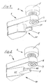
- Fig. 1:
- eine schaubildliche Darstellung einer ersten Ausführungsform der Erfindung;
- Fig. 2:
- eine schaubildliche Darstellung einer zweiten Ausführungsform der Erfindung;
- Fig. 3:
- eine schaubildliche Darstellung der ersten Ausführungsform vor dem Einführen des Positionierdornes in einen Profilstab;
- Fig. 4:
- eine schaubildliche Darstellung der ersten Ausführungsform nach dem Einführen des Positionierdornes in den Profilstab;
- Fig. 5:
- eine schaubildliche Darstellung der zweiten Ausführungsform vor dem Einführen des Positionierdornes in einen Profilstab;
- Fig. 6:
- eine schaubildliche Darstellung der zweiten Ausführungsform nach dem Einführen des Positionierdornes in den Profilstab;
- Fig. 7:
- eine schaubildliche Darstellung einer dritten Ausführungsform der Erfindung;
- Fig. 8:
- eine schaubildliche Darstellung einer vierten Ausführungsform der Erfindung;
An der Unterseite des Trägers 1 ist ein als Winkelstück ausgebildeter Anschlag 10 angeordnet, der um eine nicht näher dargestellte Zapfenschraube 11 frei schwenkbar ist. Die Anordnung der Zapfenschraube 11 ist dabei so getroffen, daß ihre Achse innerhalb der Längsmittelebene des Positionierdornes 8 im wesentlichen parallel zur Achse der Bohrbuchse 7 verläuft. Der Anschlag 10 weist zwei Schenkel 12, 13 auf, wovon der Schenkel 12 die Zapfenschraube 11 trägt und mit dem Träger 1 verbunden ist, während der Schenkel 13 als eigentliche Anschlagfläche dient und beim Einschieben des Positionierdornes 8 in die Öffnung 14 eines Profilstabes 15 die Einschubtiefe des Positionierdornes 8 in den Profilstab 15 begrenzt und hierbei eine zur Gehrungsfläche im wesentlichen parallele Lage einnimmt.
Aufgrund der vorbeschriebenen Anordnung liegt die Anschlagfläche des als Anschlag 10 dienenden Schenkels 13 im Bereich der Längsmittelebene des Positionierdornes 8 an der Gehrungsfläche des Profilstabes 15 an. Da dies der Punkt bzw der Bereich der Gehrungsfläche ist, deren Abstand zur Achse der Bohrbuchse 7 bei sich änderndem Gehrungswinkel konstant bleibt, ist auch der Abstand der Gehrungsfläche zur Bohrbuchse 7 unabhängig vom Gehrungswinkel konstant.
Die erfindungsgemäße Vorrichtung kann daher bei Verwendung einheitlicher Gelenkverbinder aufgrund des konstanten Abstandes zwischen der Mitte der Gehrungsfläche zur Mitte der Bohrbuchse 7 unabhängig vom jeweiligen Gehrungswinkel für praktisch alle vorkommenden Gehrungswinkel ohne Veränderung des Abstandes zwischen dem Anschlag 10 und der Achse der Bohrbuchse 7 verwendet werden.
Bei der Ausführungsform gemäß Fig. 2 ist der die Einschubtiefe des Positionierdornes 8 in die Öffnung 14 eines Profilstabes 15 begrenzende Anschlag 20 von einer Hülse 21 gebildet, die vom Träger 1 aufgenommen und koaxial zum Positionierdorn 8 angeordnet ist. Die Hülse 21 ist im Bereich ihres vorderen Endes beidseitig mit einer Abflachung 22 versehen, sodaß ihre eigentliche Anschlagfläche von zwei segmentartigen Kreisringflächen gebildet wird.
Dies kann bei der Ausführungsform gemäß Fig. 1 dadurch realisiert werden, daß der Anschlag 10 am Träger 1 verschieblich und feststellbar angeordnet wird. Bei der Ausführungsform gemäß Fig. 2 kann der Anschlag 20 entlang des Positionierdornes 8 verschieblich und feststellbar angeordnet werden.
Claims (9)
- Vorrichtung zum Herstellen von mittigen Bohrungen in auf Gehrung geschnittenen Profilstäben, gekennzeichnet durch
einen Träger (1) zur Aufnahme sowohl einer Bohrbuchse (7), als auch eines in eine in Längsrichtung des Profilstabes (15) verlaufende Öffnung (14) einführbaren Positionierdornes (8), wobei der Positionierdorn (8) und die Bohrbuchse (7) am Träger (1) derart angeordnet sind, daß die Achse der Bohrbuchse (7) und die Längsmittelebene des Positionierdornes (8) in einer im wesentlichen senkrechten Ebene liegen, und durch einen zur Begrenzung der Einschubtiefe des Positionierdornes (8) in den Profilstab (15) dienenden Anschlag (10, 20, 30, 40), dessen Anschlagfläche an der Gehrungsfläche des Profilstabes (15) derart in Anlage bringbar ist, daß der Abstand zwischen dem Schnittpunkt bzw der Schnittgeraden der Gehrungsfläche und der Längsmittelebene des Positionierdornes einerseits und der Achse der Bohrbuchse 7 andererseits konstant ist. - Vorrichtung nach Anspruch 1, dadurch gekennzeichnet, daß
der Anschlag (20) von einer vom Träger (1) aufgenommenen Hülse (21) gebildet ist, die koaxial zum Positionierdorn (8) angeordnet und im Bereich ihres freien Endes zur Bildung einer Anschlagfläche keilförmig ausgebildet ist. - Vorrichtung nach Anspruch 1, dadurch gekennzeichnet, daß
der Anschlag (10) von einem an einer Unterseite (2) des Trägers (1) angeordneten Winkelstück gebildet ist, das um eine zur Achse der Bohrbuchse (7) parallel gerichtete Achse frei schwenkbar ist, die innerhalb der Längsmittelebene des Positionierdornes (8) liegt. - Vorrichtung nach Anspruch 1, dadurch gekennzeichnet, daß
der Anschlag (30) von einem am Träger (1) ausgebildeten Halbzylinder (31) gebildet ist, dessen Achse innerhalb der Längsmittelebene des Positionierdornes (8) angeordnet und parallel zur Achse der Bohrbuchse (7) gerichtet ist. - Vorrichtung nach Anspruch 1, dadurch gekennzeichnet, daß
der Anschlag (40) von einem am Träger (1) ausgebildeten Keil (41) gebildet ist, dessen stirnseitige Begrenzung (42) innerhalb der Längsmittelebene des Positionierdornes (8) und parallel zur Achse der Bohrbuchse (7) verläuft. - Vorrichtung nach einem oder mehreren der Ansprüche 1 bis 3, dadurch gekennzeichnet, daß
der Abstand zwischen der Bohrbuchse (7) und dem Anschlag (10 bzw 20) einstellbar ist. - Vorrichtung nach einem oder mehreren der Ansprüche 1 bis 5, da
durch gekennzeichnet, daß
der Träger (1) mittels einer Klemmeinrichtung (4) auf den Profilstab (15) aufklemmbar ist. - Vorrichtung nach Anspruch 7, dadurch gekennzeichnet, daß die Klemmeinrichtung (4) von einer in den Träger (1) einschraubbaren Klemmschraube (5) gebildet ist.
- Vorrichtung nach Anspruch 8, dadurch gekennzeichnet, daß die Klemmschraube (5) als Bohrbuchse (7) ausgebildet ist.
Applications Claiming Priority (2)
| Application Number | Priority Date | Filing Date | Title |
|---|---|---|---|
| DE2003161896 DE10361896A1 (de) | 2003-12-28 | 2003-12-28 | Vorrichtung zum Herstellen von mittigen Bohrungen in auf Gehrung geschnittenen Profilstäben |
| DE10361896 | 2003-12-28 |
Publications (3)
| Publication Number | Publication Date |
|---|---|
| EP1552898A2 true EP1552898A2 (de) | 2005-07-13 |
| EP1552898A3 EP1552898A3 (de) | 2012-01-11 |
| EP1552898B1 EP1552898B1 (de) | 2012-10-24 |
Family
ID=34585315
Family Applications (1)
| Application Number | Title | Priority Date | Filing Date |
|---|---|---|---|
| EP20040029652 Expired - Lifetime EP1552898B1 (de) | 2003-12-28 | 2004-12-15 | Vorrichtung zum Herstellen von mittigen Bohrungen in auf Gehrung geschnittenen Profilstäben |
Country Status (3)
| Country | Link |
|---|---|
| EP (1) | EP1552898B1 (de) |
| DE (1) | DE10361896A1 (de) |
| ES (1) | ES2398169T3 (de) |
Families Citing this family (2)
| Publication number | Priority date | Publication date | Assignee | Title |
|---|---|---|---|---|
| US10662650B2 (en) | 2017-10-31 | 2020-05-26 | Vention Inc. | T-slot extrusion structure |
| CN113275630A (zh) * | 2021-05-31 | 2021-08-20 | 贵州航天电子科技有限公司 | 一种钻孔异地定位工装及其使用方法 |
Family Cites Families (3)
| Publication number | Priority date | Publication date | Assignee | Title |
|---|---|---|---|---|
| GB154073A (en) * | 1919-12-03 | 1920-11-25 | Bertram Harold Cope | A new or improved jig or appliance for use in the attachment of cylinder and the like locks and latches |
| US5733077A (en) * | 1996-07-02 | 1998-03-31 | The Hilsinger Company Lp | Lens drill guide |
| DE29904802U1 (de) * | 1998-06-02 | 1999-08-26 | Ratiomatic Verbindungstechnik Walter Fischer GmbH, 49328 Melle | Vorrichtung zur Herstellung von Bohrungen |
-
2003
- 2003-12-28 DE DE2003161896 patent/DE10361896A1/de not_active Withdrawn
-
2004
- 2004-12-15 EP EP20040029652 patent/EP1552898B1/de not_active Expired - Lifetime
- 2004-12-15 ES ES04029652T patent/ES2398169T3/es not_active Expired - Lifetime
Also Published As
| Publication number | Publication date |
|---|---|
| DE10361896A1 (de) | 2005-08-11 |
| EP1552898B1 (de) | 2012-10-24 |
| EP1552898A3 (de) | 2012-01-11 |
| ES2398169T3 (es) | 2013-03-14 |
Similar Documents
| Publication | Publication Date | Title |
|---|---|---|
| DE69206191T2 (de) | Zapfenverbindungshilfsgerät für Handoberfräse. | |
| DE2437724C2 (de) | Verdübelungs-Bohrlehre für zwei stirn-flachseitig miteinander zu verdübelnde Werkstücke | |
| EP1796570A1 (de) | Kalibriervorrichtung | |
| DE3824462C2 (de) | ||
| DE4118991C2 (de) | Bohrlehre zur Ausbildung bestimmter Bohrlochbilder an Werkstücken | |
| DE2919043A1 (de) | Messeinrichtung fuer rohrgewinde | |
| DE3105180A1 (de) | Werkzeug zum verduebeln | |
| DE3020970A1 (de) | Bohrlehre | |
| EP0050210A2 (de) | Bohrschablone | |
| EP1552898B1 (de) | Vorrichtung zum Herstellen von mittigen Bohrungen in auf Gehrung geschnittenen Profilstäben | |
| DE2526857A1 (de) | Rahmenpresse zur schaffung von eckverbindungen an fenster- und tuerrahmen | |
| DE3916759C2 (de) | ||
| DE2750869A1 (de) | Hilfsgeraet zum bohren der duebelloecher in miteinander zu verduebelnden brettern o.dgl. | |
| EP3563160B1 (de) | Adaptiervorrichtung, halteklammer und verfahren zum positionieren eines leiterpaares eines zu messenden kabels | |
| DE3828239C2 (de) | ||
| EP1314516B1 (de) | Halteelement | |
| DE10134580B4 (de) | Dübellehre | |
| DE2918470C2 (de) | Vorrichtung zum Spannen eines Möbelkorpus und zum Einbringen von Bohrungen für Schraubverbinder | |
| DE1930999C3 (de) | Verbindungsmuffe | |
| DE3039673A1 (de) | Geraet zur fuehrung eines bohrwerkzeuges | |
| DE603023C (de) | Bohrlehre zum gleichzeitigen Bohren von Loechern in die Stege und Flanschen von Profileisen | |
| DE102005043765A1 (de) | Gehrungsverbindersystem | |
| DE102017131409B3 (de) | Spann- und Fügevorrichtung | |
| DE29500192U1 (de) | Spannvorrichtung zum Fräsen von Zapfenlöchern und Zapfen für eine Fräsmaschine | |
| DE2513319B2 (de) | Spannvorrichtung mit zugehöriger Schraubzwinge |
Legal Events
| Date | Code | Title | Description |
|---|---|---|---|
| PUAI | Public reference made under article 153(3) epc to a published international application that has entered the european phase |
Free format text: ORIGINAL CODE: 0009012 |
|
| AK | Designated contracting states |
Kind code of ref document: A2 Designated state(s): AT BE BG CH CY CZ DE DK EE ES FI FR GB GR HU IE IS IT LI LT LU MC NL PL PT RO SE SI SK TR |
|
| AX | Request for extension of the european patent |
Extension state: AL BA HR LV MK YU |
|
| PUAL | Search report despatched |
Free format text: ORIGINAL CODE: 0009013 |
|
| AK | Designated contracting states |
Kind code of ref document: A3 Designated state(s): AT BE BG CH CY CZ DE DK EE ES FI FR GB GR HU IE IS IT LI LT LU MC NL PL PT RO SE SI SK TR |
|
| AX | Request for extension of the european patent |
Extension state: AL BA HR LV MK YU |
|
| RIC1 | Information provided on ipc code assigned before grant |
Ipc: B23B 47/28 20060101AFI20111205BHEP |
|
| 17P | Request for examination filed |
Effective date: 20120121 |
|
| GRAC | Information related to communication of intention to grant a patent modified |
Free format text: ORIGINAL CODE: EPIDOSCIGR1 |
|
| GRAP | Despatch of communication of intention to grant a patent |
Free format text: ORIGINAL CODE: EPIDOSNIGR1 |
|
| GRAS | Grant fee paid |
Free format text: ORIGINAL CODE: EPIDOSNIGR3 |
|
| AKX | Designation fees paid |
Designated state(s): AT BE BG CH CY CZ DE DK EE ES FI FR GB GR HU IE IS IT LI LT LU MC NL PL PT RO SE SI SK TR |
|
| GRAA | (expected) grant |
Free format text: ORIGINAL CODE: 0009210 |
|
| AK | Designated contracting states |
Kind code of ref document: B1 Designated state(s): AT BE BG CH CY CZ DE DK EE ES FI FR GB GR HU IE IS IT LI LT LU MC NL PL PT RO SE SI SK TR |
|
| REG | Reference to a national code |
Ref country code: GB Ref legal event code: FG4D Free format text: NOT ENGLISH Ref country code: DE Ref legal event code: R081 Ref document number: 502004013829 Country of ref document: DE Owner name: MINITEC MASCHINENBAU GMBH & CO. KG, DE Free format text: FORMER OWNER: MINITEC MASCHINENBAU GMBH & CO. KG, 66914 WALDMOHR, DE |
|
| REG | Reference to a national code |
Ref country code: CH Ref legal event code: EP |
|
| REG | Reference to a national code |
Ref country code: AT Ref legal event code: REF Ref document number: 580631 Country of ref document: AT Kind code of ref document: T Effective date: 20121115 |
|
| REG | Reference to a national code |
Ref country code: IE Ref legal event code: FG4D Free format text: LANGUAGE OF EP DOCUMENT: GERMAN |
|
| REG | Reference to a national code |
Ref country code: DE Ref legal event code: R096 Ref document number: 502004013829 Country of ref document: DE Effective date: 20121220 |
|
| REG | Reference to a national code |
Ref country code: ES Ref legal event code: FG2A Ref document number: 2398169 Country of ref document: ES Kind code of ref document: T3 Effective date: 20130314 |
|
| REG | Reference to a national code |
Ref country code: NL Ref legal event code: VDEP Effective date: 20121024 |
|
| PG25 | Lapsed in a contracting state [announced via postgrant information from national office to epo] |
Ref country code: FI Free format text: LAPSE BECAUSE OF FAILURE TO SUBMIT A TRANSLATION OF THE DESCRIPTION OR TO PAY THE FEE WITHIN THE PRESCRIBED TIME-LIMIT Effective date: 20121024 Ref country code: SE Free format text: LAPSE BECAUSE OF FAILURE TO SUBMIT A TRANSLATION OF THE DESCRIPTION OR TO PAY THE FEE WITHIN THE PRESCRIBED TIME-LIMIT Effective date: 20121024 Ref country code: IS Free format text: LAPSE BECAUSE OF FAILURE TO SUBMIT A TRANSLATION OF THE DESCRIPTION OR TO PAY THE FEE WITHIN THE PRESCRIBED TIME-LIMIT Effective date: 20130224 Ref country code: NL Free format text: LAPSE BECAUSE OF FAILURE TO SUBMIT A TRANSLATION OF THE DESCRIPTION OR TO PAY THE FEE WITHIN THE PRESCRIBED TIME-LIMIT Effective date: 20121024 |
|
| PG25 | Lapsed in a contracting state [announced via postgrant information from national office to epo] |
Ref country code: PT Free format text: LAPSE BECAUSE OF FAILURE TO SUBMIT A TRANSLATION OF THE DESCRIPTION OR TO PAY THE FEE WITHIN THE PRESCRIBED TIME-LIMIT Effective date: 20130225 Ref country code: GR Free format text: LAPSE BECAUSE OF FAILURE TO SUBMIT A TRANSLATION OF THE DESCRIPTION OR TO PAY THE FEE WITHIN THE PRESCRIBED TIME-LIMIT Effective date: 20130125 Ref country code: PL Free format text: LAPSE BECAUSE OF FAILURE TO SUBMIT A TRANSLATION OF THE DESCRIPTION OR TO PAY THE FEE WITHIN THE PRESCRIBED TIME-LIMIT Effective date: 20121024 Ref country code: CY Free format text: LAPSE BECAUSE OF FAILURE TO SUBMIT A TRANSLATION OF THE DESCRIPTION OR TO PAY THE FEE WITHIN THE PRESCRIBED TIME-LIMIT Effective date: 20121024 Ref country code: SI Free format text: LAPSE BECAUSE OF FAILURE TO SUBMIT A TRANSLATION OF THE DESCRIPTION OR TO PAY THE FEE WITHIN THE PRESCRIBED TIME-LIMIT Effective date: 20121024 |
|
| BERE | Be: lapsed |
Owner name: MINITEC MASCHINENBAU G.M.B.H. & CO. KG Effective date: 20121231 |
|
| PG25 | Lapsed in a contracting state [announced via postgrant information from national office to epo] |
Ref country code: MC Free format text: LAPSE BECAUSE OF NON-PAYMENT OF DUE FEES Effective date: 20121231 Ref country code: DK Free format text: LAPSE BECAUSE OF FAILURE TO SUBMIT A TRANSLATION OF THE DESCRIPTION OR TO PAY THE FEE WITHIN THE PRESCRIBED TIME-LIMIT Effective date: 20121024 Ref country code: EE Free format text: LAPSE BECAUSE OF FAILURE TO SUBMIT A TRANSLATION OF THE DESCRIPTION OR TO PAY THE FEE WITHIN THE PRESCRIBED TIME-LIMIT Effective date: 20121024 Ref country code: CZ Free format text: LAPSE BECAUSE OF FAILURE TO SUBMIT A TRANSLATION OF THE DESCRIPTION OR TO PAY THE FEE WITHIN THE PRESCRIBED TIME-LIMIT Effective date: 20121024 Ref country code: SK Free format text: LAPSE BECAUSE OF FAILURE TO SUBMIT A TRANSLATION OF THE DESCRIPTION OR TO PAY THE FEE WITHIN THE PRESCRIBED TIME-LIMIT Effective date: 20121024 Ref country code: BG Free format text: LAPSE BECAUSE OF FAILURE TO SUBMIT A TRANSLATION OF THE DESCRIPTION OR TO PAY THE FEE WITHIN THE PRESCRIBED TIME-LIMIT Effective date: 20130124 |
|
| PG25 | Lapsed in a contracting state [announced via postgrant information from national office to epo] |
Ref country code: RO Free format text: LAPSE BECAUSE OF FAILURE TO SUBMIT A TRANSLATION OF THE DESCRIPTION OR TO PAY THE FEE WITHIN THE PRESCRIBED TIME-LIMIT Effective date: 20121024 |
|
| PLBE | No opposition filed within time limit |
Free format text: ORIGINAL CODE: 0009261 |
|
| STAA | Information on the status of an ep patent application or granted ep patent |
Free format text: STATUS: NO OPPOSITION FILED WITHIN TIME LIMIT |
|
| REG | Reference to a national code |
Ref country code: IE Ref legal event code: MM4A |
|
| PG25 | Lapsed in a contracting state [announced via postgrant information from national office to epo] |
Ref country code: BE Free format text: LAPSE BECAUSE OF NON-PAYMENT OF DUE FEES Effective date: 20121231 |
|
| 26N | No opposition filed |
Effective date: 20130725 |
|
| PG25 | Lapsed in a contracting state [announced via postgrant information from national office to epo] |
Ref country code: IE Free format text: LAPSE BECAUSE OF NON-PAYMENT OF DUE FEES Effective date: 20121215 |
|
| REG | Reference to a national code |
Ref country code: DE Ref legal event code: R097 Ref document number: 502004013829 Country of ref document: DE Effective date: 20130725 |
|
| PG25 | Lapsed in a contracting state [announced via postgrant information from national office to epo] |
Ref country code: TR Free format text: LAPSE BECAUSE OF FAILURE TO SUBMIT A TRANSLATION OF THE DESCRIPTION OR TO PAY THE FEE WITHIN THE PRESCRIBED TIME-LIMIT Effective date: 20121024 |
|
| PG25 | Lapsed in a contracting state [announced via postgrant information from national office to epo] |
Ref country code: LU Free format text: LAPSE BECAUSE OF NON-PAYMENT OF DUE FEES Effective date: 20121215 |
|
| PG25 | Lapsed in a contracting state [announced via postgrant information from national office to epo] |
Ref country code: LT Free format text: LAPSE BECAUSE OF FAILURE TO SUBMIT A TRANSLATION OF THE DESCRIPTION OR TO PAY THE FEE WITHIN THE PRESCRIBED TIME-LIMIT Effective date: 20121024 Ref country code: HU Free format text: LAPSE BECAUSE OF FAILURE TO SUBMIT A TRANSLATION OF THE DESCRIPTION OR TO PAY THE FEE WITHIN THE PRESCRIBED TIME-LIMIT Effective date: 20041215 |
|
| REG | Reference to a national code |
Ref country code: FR Ref legal event code: PLFP Year of fee payment: 12 |
|
| REG | Reference to a national code |
Ref country code: FR Ref legal event code: PLFP Year of fee payment: 13 |
|
| REG | Reference to a national code |
Ref country code: FR Ref legal event code: PLFP Year of fee payment: 14 |
|
| PGFP | Annual fee paid to national office [announced via postgrant information from national office to epo] |
Ref country code: GB Payment date: 20240619 Year of fee payment: 20 |
|
| PGFP | Annual fee paid to national office [announced via postgrant information from national office to epo] |
Ref country code: DE Payment date: 20240619 Year of fee payment: 20 |
|
| PGFP | Annual fee paid to national office [announced via postgrant information from national office to epo] |
Ref country code: CH Payment date: 20240624 Year of fee payment: 20 |
|
| PGFP | Annual fee paid to national office [announced via postgrant information from national office to epo] |
Ref country code: ES Payment date: 20240626 Year of fee payment: 20 |
|
| PGFP | Annual fee paid to national office [announced via postgrant information from national office to epo] |
Ref country code: AT Payment date: 20240620 Year of fee payment: 20 |
|
| PGFP | Annual fee paid to national office [announced via postgrant information from national office to epo] |
Ref country code: FR Payment date: 20240619 Year of fee payment: 20 |
|
| PGFP | Annual fee paid to national office [announced via postgrant information from national office to epo] |
Ref country code: IT Payment date: 20240625 Year of fee payment: 20 |
|
| REG | Reference to a national code |
Ref country code: DE Ref legal event code: R071 Ref document number: 502004013829 Country of ref document: DE |
|
| REG | Reference to a national code |
Ref country code: CH Ref legal event code: PL Ref country code: ES Ref legal event code: FD2A Effective date: 20241230 |
|
| REG | Reference to a national code |
Ref country code: GB Ref legal event code: PE20 Expiry date: 20241214 |
|
| PG25 | Lapsed in a contracting state [announced via postgrant information from national office to epo] |
Ref country code: GB Free format text: LAPSE BECAUSE OF EXPIRATION OF PROTECTION Effective date: 20241214 |
|
| PG25 | Lapsed in a contracting state [announced via postgrant information from national office to epo] |
Ref country code: ES Free format text: LAPSE BECAUSE OF EXPIRATION OF PROTECTION Effective date: 20241216 |
|
| PG25 | Lapsed in a contracting state [announced via postgrant information from national office to epo] |
Ref country code: GB Free format text: LAPSE BECAUSE OF EXPIRATION OF PROTECTION Effective date: 20241214 Ref country code: ES Free format text: LAPSE BECAUSE OF EXPIRATION OF PROTECTION Effective date: 20241216 |
|
| REG | Reference to a national code |
Ref country code: AT Ref legal event code: MK07 Ref document number: 580631 Country of ref document: AT Kind code of ref document: T Effective date: 20241215 |