EP1552148B1 - Mikropumpe und verfahren zu ihrer herstellung - Google Patents
Mikropumpe und verfahren zu ihrer herstellung Download PDFInfo
- Publication number
- EP1552148B1 EP1552148B1 EP03798890A EP03798890A EP1552148B1 EP 1552148 B1 EP1552148 B1 EP 1552148B1 EP 03798890 A EP03798890 A EP 03798890A EP 03798890 A EP03798890 A EP 03798890A EP 1552148 B1 EP1552148 B1 EP 1552148B1
- Authority
- EP
- European Patent Office
- Prior art keywords
- micropump according
- valve
- seat
- diaphragm
- micropump
- Prior art date
- Legal status (The legal status is an assumption and is not a legal conclusion. Google has not performed a legal analysis and makes no representation as to the accuracy of the status listed.)
- Expired - Lifetime
Links
Images

Classifications
-
- F—MECHANICAL ENGINEERING; LIGHTING; HEATING; WEAPONS; BLASTING
- F04—POSITIVE - DISPLACEMENT MACHINES FOR LIQUIDS; PUMPS FOR LIQUIDS OR ELASTIC FLUIDS
- F04B—POSITIVE-DISPLACEMENT MACHINES FOR LIQUIDS; PUMPS
- F04B53/00—Component parts, details or accessories not provided for in, or of interest apart from, groups F04B1/00 - F04B23/00 or F04B39/00 - F04B47/00
- F04B53/10—Valves; Arrangement of valves
- F04B53/1037—Flap valves
- F04B53/1047—Flap valves the valve being formed by one or more flexible elements
- F04B53/106—Flap valves the valve being formed by one or more flexible elements the valve being a membrane
- F04B53/1062—Flap valves the valve being formed by one or more flexible elements the valve being a membrane fixed at two or more points at its periphery
-
- F—MECHANICAL ENGINEERING; LIGHTING; HEATING; WEAPONS; BLASTING
- F04—POSITIVE - DISPLACEMENT MACHINES FOR LIQUIDS; PUMPS FOR LIQUIDS OR ELASTIC FLUIDS
- F04B—POSITIVE-DISPLACEMENT MACHINES FOR LIQUIDS; PUMPS
- F04B43/00—Machines, pumps, or pumping installations having flexible working members
- F04B43/02—Machines, pumps, or pumping installations having flexible working members having plate-like flexible members, e.g. diaphragms
- F04B43/04—Pumps having electric drive
- F04B43/043—Micropumps
- F04B43/046—Micropumps with piezoelectric drive
-
- F—MECHANICAL ENGINEERING; LIGHTING; HEATING; WEAPONS; BLASTING
- F16—ENGINEERING ELEMENTS AND UNITS; GENERAL MEASURES FOR PRODUCING AND MAINTAINING EFFECTIVE FUNCTIONING OF MACHINES OR INSTALLATIONS; THERMAL INSULATION IN GENERAL
- F16K—VALVES; TAPS; COCKS; ACTUATING-FLOATS; DEVICES FOR VENTING OR AERATING
- F16K15/00—Check valves
- F16K15/14—Check valves with flexible valve members
- F16K15/144—Check valves with flexible valve members the closure elements being fixed along all or a part of their periphery
Definitions
- the invention relates to a micropump having a pumping membrane which is movable by changing the volume of a pumping chamber adjacent to the pumping membrane and a base part, and two arranged in recesses in the base part, responsive to the pressure in the pumping chamber valves for mutual opening and blocking of an inlet - And outlet for the medium to be pumped, the valves are formed without common components by as such functional, a valve seat and valve body having valve assemblies and wherein the valve assemblies forming a valve seat seat member with a recess formed by an increase in height of a bottom plate for receiving a Having the valve body forming spring component.
- the lateral dimensions of such, entirely or predominantly made of plastic micropumps are preferably between 5 and 30 mm at a height of 0.5 to 5 mm.
- the flow rates for liquids are between about 10 -6 and 0.05 l / min, for gases between 10 -5 and 0.2 l / min.
- Main areas of application are chemical and biochemical analysis, micro reaction technology, the transport of gases, the transport and the dosing of pharmaceutical agents, sample liquids, adhesives, fuels or lubricants.
- Plastic micropumps have the advantage over silicon or metal that, in addition to the use of inexpensive starting materials, efficient manufacturing processes such as injection molding can be used.
- efficient manufacturing processes such as injection molding can be used.
- different plastics can be used with the same construction, such as polycarbonate, polypropylene, polyethylene, cycloolefin, polyetheretherketone, polyphenylene sulfide or fluoroplastics.
- DE 44 02 119 describes a micropump made of plastic with a membrane arranged between two housing parts, which serves both as a pumping membrane and for the formation of movable valve bodies and is broken at valve seats.
- a pumping membrane On the upper side of a two-part, in the interior recesses for valves having base part, a pumping membrane is attached to form a pumping chamber, which is deformable by a piezoelectric actuator.
- a valve membrane arranged between the two parts of the base part has an opening at the two valve seats and thus forms a component common to both valves.
- a micropump of the type mentioned in the introduction is disclosed in EP 0 424 087 A1.
- the seat component of the two valve assemblies of this micropump made of plastic has a retaining pin protruding from the base plate, which engages in an opening in the spring component.
- a depression covering, provided with a through hole plate holds the seated on the pin spring member axially on the pin.
- the present invention has for its object to provide a new micropump of the type mentioned, which can be produced over known micropumps with less effort.
- the problem solving micropump according to the invention is characterized in that the valve assemblies are formed only by the seat and spring member, and that the spring member centered by the edge elevation and in an annular edge region is welded to the bottom plate of the seat component.
- both valve assemblies i. the inlet valve assembly and the outlet valve assembly, be identical, the valve seat facing in each case in the direction of the flow.
- the recesses are formed as depressions open to the pumping chamber, in which the valve assemblies can be accurately positioned for the final assembly of the pump with little effort.
- the height of the valve assembly is equal to the depth of the recess.
- the formation of dead volume is largely avoided.
- the seat component is rotationally symmetrical and the valve body is designed to close or release a valve opening in the seat component, which is preferably arranged coaxially to the rotational symmetry axis.
- the spring member may include a lip member extending inwardly from the rim portion for closing or releasing the valve opening.
- differently shaped spring components can be combined with the same seat component. Pumps with different properties then differ only with respect to the spring components.
- the micropump is further composed of a prefabricated base assembly, which consists of the base part and hose connections, and a prefabricated actuator assembly which comprises the membrane and possibly a piezoelectric disc connected to the membrane.
- Such a modular construction further contributes to the reduction of the manufacturing cost.
- Separate product development, production and quality assurance for the components of the pump increase the production reliability as well as the flexibility and the conversion effort in the series production of different pump variants.
- the self-contained assemblies allow each other large, the assembly facilitating positioning tolerances.
- the base assembly apart from the recesses in the base part, and the Aktorbauffle rotationally symmetrical, wherein the pumping membrane with the base part is optionally connected via a support ring which rests on a ring seat, in particular an annular shoulder on the base part.
- the rotationally symmetrical parts or the tools required for their manufacture can be produced with relatively little effort. Due to the support ring seated on the ring seat, the actuator assembly can be centered during assembly with little effort on the base assembly without position control.
- the base part is preferably a disk part, wherein the channels for the inflow and outflow of the pumped medium expediently extend perpendicular to the disk plane by the shortest path through the base part. This is advantageous in order to minimize the flow resistance within the micropump.
- the base assembly may be integral with the hose connectors e.g. be made as an injection molded part.
- the coming into contact with the medium parts of the pump are made of a plastic that is resistant to the fluid and possibly not made of plastic parts to protect against aggressive media.
- the membrane can be formed of multiple layers, e.g. a shielded by a plastic layer layer may consist of a metal.
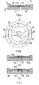
- Fig. 1 the reference numeral 1 on a disc-shaped base part with an annular shoulder 17 on the periphery.
- an inlet port 2 and an outlet port 3 are attached on the base part 1.
- a ring carrier 4 connected to the ring carrier 4 at its outer edge by gluing or welding membrane 5, which in turn is glued to a piezoelectric disk 6.
- the ring carrier 4 could also be integrally connected to the membrane 5.
- a pumping chamber 7 is formed between the membrane 5 and connected to the membrane by gluing or welding base part 1.
- An inlet channel 8 connects to the inlet connection 2 and an outlet channel 9 connects to the outlet connection 3, the two channels each opening into a round-cylindrical recess 10 or 11 in the base part 1.
- the channels 8 and 9 are arranged concentrically to the respective recesses 10 and 11.
- the seat component 12 has an opening 14 aligned with the inlet channel 8.
- the micropump shown in FIGS. 1 and 2 is rotationally symmetrical about an axis 15.
- the connections are; Channels and valve assemblies arranged symmetrically to a rotational symmetry axis 15 containing the pump in halves dividing plane 16.
- the assembled from the modules pump is easy to manufacture.
- the annular shoulder 17 ensures centering of the actuator assembly.
- the piezoelectric disk 6 deflects the membrane 5, whereby the volume of the pumping chamber 7 increases.
- the diaphragm 5 is dented in the relevant embodiment. Due to the resulting negative pressure, the spring component 13 of the inlet valve assembly 40 lifts off from its opening 14. Via the inlet channel 8 through the released opening 14 and cutouts in the spring component (FIG. 5), medium to be pumped flows into the pumping chamber 7.
- the membrane 5 has its planar shape as shown in FIG .
- the spring member 13 of the inlet valve assembly 40 closes.
- the spring member 13 of the outlet valve assembly 41 lifts from the opening 14 thereof.
- the spring component 13 of the outlet valve assembly 41 remains set back relative to the bottoms of the recess 11.
- a medium to be conveyed can now flow through the opening 14 of the outlet valve assembly 41, a gap 42 formed between the spring component 13 and the bottom of the recess 11, and the outlet channel 9.
- the actuator periodically moves at frequencies typically between 10 ° and a few 10 2 Hz.
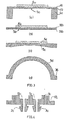
- FIG. 3 a shows an actuator assembly with a carrier ring 4 a, a membrane 5 a and a piezo disk 6 a, wherein the membrane 5 a is composed of two layers 18 and 19.
- the layer 18 is made of a metal, e.g. Steel or brass.
- the adjacent to the pumping chamber and thus the medium layer 19 is made of a plastic.
- the metal layer a desired deformation behavior of the membrane is achieved.
- the plastic layer secures the metal layer against aggressive material and is resistant to the pumped medium.
- Partially crystalline plastics such as polypropylene, amorphous plastics, such as polycarbonate, or high-performance plastics, such as polyphenylene sulfide, polyether ether ketone or fluorine-containing plastics can be used for this purpose.
- An actuator assembly shown in FIG. 3b has a membrane 5b consisting of two such layers 18b and 19b and a piezo disk 6b.
- the assembly is placed without support ring directly on a base part, which differs from the base part of Fig. 1 in that no annular shoulder 17 is provided. Instead, a ridge elevation could form a centering seat. This results in a self-priming, suitable for the promotion of small flow rates pump with a fluctuating between 0 and a maximum volume of the pumping chamber, the diaphragm 5b is only bagged by the piezoelectric disc 6b.
- FIG. 3c A further actuator assembly for such a pump with a pump chamber volume varying between 0 and a maximum value is shown in FIG. 3c.
- a membrane 5c connected to a piezo disk 6c has, on its side facing the pumping chamber, a recess corresponding to the maximum pumping chamber volume, which disappears when the membrane 5c is dented by the piezoelectric disk 6c.
- Fig. 3d shows an actuator assembly with a cap-shaped membrane 5d made of plastic, which is connectable via a flange 36 with a base assembly.
- the resilient membrane 5d can be dented, for example, directly by hand with the thumb or by a suitable plunger of a temporarily or permanently connected to the pump drive.
- a piezo disk can be longer membrane strokes and correspondingly larger Achieve changes in the pumping chamber volume.
- a micropump with such a membrane could be used for example in the context of environmental protection for obtaining samples.
- Fig. 4 shows an alternative embodiment of a base assembly with a base part 1c integrally formed with an inlet port 2c and an outlet port 3c.
- FIGs 5 and 6 show in greater detail the structure of the valve assemblies 40 and 41 used in the micromembrane pump of Figures 1 and 2.
- the seat member 12 of the valve assembly has a bottom plate 20 and an annular rim elevation 21, through which a vessel-like recess for the spring member 13 is formed.
- the height of the edge elevation is equal to the depth of the recesses 10 and 11.
- the top of the spring member is set back against the edge elevation 21.
- the spring component 13 is adhesively bonded or welded to the seat component 12 via an annular edge region 22.
- the spring member 13 a the annular edge portion 22 diametrically spanning lip element 23 with a widening 24 in the region of a valve seat 29.
- the spring component 13 can be produced from a plastic film, wherein the film thickness can be between 0.01 and 0.3 mm.
- the lip element 23, in particular its widening 24, lifts off from the seating area, releasing the opening 14, or lies against the seat area closing the opening.
- medium emerging from the opening 14 can flow through openings formed in the spring component 13 through cutouts 25 and 26 and reach the pumping chamber 7 or the outlet channel 9.
- a ring elevation 27 extending from a base plate 20a is formed in the region of the valve seat, which provides a suitable prestressing of a resilient lip element 23a and thus enables a secure closure of the valve.
- an elevated edge seat 28 is formed, through which a lip element 23b is lifted off a bottom plate 20b over its entire length.
- a lip member 23c having a widening 24c in the seat portion is connected to the remainder of the spring member at only one end, and a slit cutout 30 is formed.
- a lip element 23d which is connected at both ends to the rest of the spring component is formed by slot cutouts 31 and 32 with a widening 24d in the region of the valve seat.
- the spring constant of this mutually connected to the rest of the spring member lip member may be higher than in the previous embodiment.
- the widening 24d is less prone to tilting and therefore sits more evenly on the valve seat than in the previous embodiment.
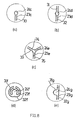
- a three-armed lip member 23e is formed with a widening 24e.
- the connection points of the lip element with the remaining foil are distributed uniformly over the circumference of a ring area provided for connection to the seat component.
- a relatively small spring constant of the lip element 23f can be combined with a uniform abutment of the expansion 24f in the valve seat region.
- FIG. 8e shows a spring component with a straight lip element 23g formed by two slot cutouts 31g and 32g with an expansion 24g protruding laterally toward the center of the spring component.
- All spring components shown in FIG. 8 have narrow openings following the contours of the lip element, which advantageously do not form a large dead volume.
- the spring constants of the lip element are between 0.8 mN and 0.0005 mN per micrometre deflection.
Landscapes
- Engineering & Computer Science (AREA)
- Mechanical Engineering (AREA)
- General Engineering & Computer Science (AREA)
- Reciprocating Pumps (AREA)
- Saccharide Compounds (AREA)
- Organic Low-Molecular-Weight Compounds And Preparation Thereof (AREA)
Description
- Die Erfindung betrifft eine Mikropumpe mit einer Pumpmembran, die unter Änderung des Volumens einer an die Pumpmembran und ein Basisteil grenzenden Pumpkammer bewegbar ist, und mit zwei in Ausnehmungen im Basisteil angeordneten, auf den Druck in der Pumpkammer ansprechenden Ventilen zum wechselseitigen Öffnen und Sperren eines Einlass- und Auslasskanals für das zu fördernde Medium, wobei die Ventile ohne gemeinsame Bauteile durch als solche funktionsfähige, einen Ventilsitz und Ventilkörper aufweisende Ventilbaugruppen gebildet sind und wobei die Ventilbaugruppen ein den Ventilsitz bildendes Sitzbauteil mit einer durch eine Randerhöhung einer Bodenplatte gebildeten Vertiefung für die Aufnahme eines den Ventilkörper bildenden Federbauteils aufweisen.
- Die lateralen Abmessungen solcher, ganz oder überwiegend aus Kunststoffen hergestellter Mikropumpen liegen vorzugsweise zwischen 5 und 30 mm bei einer Höhe von 0,5 bis 5 mm. Die Förderraten bewegen sich für Flüssigkeiten etwa zwischen 10-6 und 0,05l/min, für Gase zwischen 10-5 und 0,2l/min. Hauptsächliche Einsatzgebiete sind die chemische und biochemische Analytik, die Mikroreaktionstechnik, der Transport von Gasen, der Transport und die Dosierung von pharmazeutischen Wirkstoffen, Probenflüssigkeiten, Klebstoffen, Brennstoffen oder Schmiermitteln.
- Mikropumpen aus Kunststoff haben gegenüber solchen aus Silizium oder Metallen den Vorteil, dass neben der Verwendung preiswerter Ausgangsmaterialien effiziente Herstellungsvefahren, wie das Spritzgießen, angewendet werden können. Je nach Anforderungen, beispielsweise in bezug auf optische Transparenz, Festigkeit, Hydrophilität, Hydrophobität oder chemische Resistenz, sind bei gleicher Konstruktion unterschiedliche Kunststoffe einsetzbar, wie beispielsweise Polycarbonat, Polypropylen, Polyethylen, Zykloolephincopolymer, Polyetheretherketon, Polyphenylensulfid oder Fluorkunststoffe.
- Die DE 44 02 119 beschreibt eine Mikropumpe aus Kunststoff mit einer zwischen zwei Gehäuseteilen angeordneten Membran, die sowohl als Pumpmembran als auch zur Bildung von beweglichen Ventilkörpern dient und an Ventilsitzen durchbrochen ist.
- Eine weitere Mikropumpe geht aus der DE 197 20 482 hervor. An der Oberseite eines zweiteiligen, im Inneren Ausnehmungen für Ventile aufweisenden Basisteils ist unter Bildung einer Pumpkammer eine Pumpmembran angebracht, die durch einen Piezoaktor verformbar ist. Eine zwischen den beiden Teilen des Basisteils angeordnete Ventilmembran weist an den beiden Ventilsitzen einen Durchbruch auf und bildet so ein beiden Ventilen gemeinsames Bauteil.
- Die Herstellung solcher Mikropumpen unter Verwendung verhältnismäßig großer, an der Bildung beider Ventile beteiligter Ventilmembranen ist sehr aufwendig. Insbesondere bereitet es Schwierigkeiten, die Durchbrüche in der Membran mit der für die Funktion der Ventile erforderlichen Genauigkeit an den Ventilsitzen anzuordnen. Zum einen führen für Kunststoffmaterialien typische Verzugs- und Schwindungseffekte zu großen Positionsschwankungen der Durchbrüche auf der Membran. Zum anderen kann es bei der Montage der dünnen, schwer zu handhabenden Membranfolie leicht zu Fehlanordnungen der Durchbrüche an den Ventilsitzen kommen. Unter den Bedingungen einer Serienfertigung ist die Produktionsausbeute daher gering.
- Eine Mikropumpe der eingangs erwähnten Art geht aus der EP 0 424 087 A1 hervor. Das Sitzbauteil der beiden aus Kunststoff hergestellten Ventilbaugruppen dieser Mikropumpe weist einen von der Bodenplatte vorstehenden Haltezapfen auf, welcher in eine Öffnung im Federbauteil eingreift. Eine die Vertiefung abdeckende, mit einer Durchgangsöffnung versehene Platte hält das auf dem Zapfen sitzende Federbauteil axial auf dem Zapfen fest.
- Der vorliegenden Erfindung liegt die Aufgabe zugrunde, eine neue Mikropumpe der eingangs erwähnten Art zu schaffen, die sich gegenüber bekannten derartigen Mikropumpen mit geringerem Aufwand herstellen lässt.
- Die diese Aufgabe lösende Mikropumpe nach der Erfindung ist dadurch gekennzeichnet, dass die Ventilbaugruppen lediglich durch das Sitz- und Federbauteil gebildet sind, und dass das Federbauteil durch die Randerhöhung zentriert und in einem ringförmigen Randbereich mit der Bodenplatte des Sitzbauteils verschweißt ist.
- Die Fertigung der nur zweiteiligen Ventilbaugruppen unter Zentrierung des Federbauteils durch die Randerhöhung erfordert einen geringeren Aufwand als die Herstellung derartige Ventilbaugruppen nach dem Stand der Technik.
- Vorteilhaft können beide Ventilbaugruppen, d.h. die Einlassventilbaugruppe und die Auslassventilbaugruppe, baugleich sein, wobei der Ventilsitz jeweils in die Richtung des Förderstroms weist. Auch diese; den Anteil gleicher Bauteile erhöhende Maßnahme trägt zur Verringerung des Herstellungsaufwands der Mikropumpe bei.
- In der bevorzugten Ausführungsform der Erfindung sind die Ausnehmungen als zur Pumpkammer offene Einsenkungen gebildet, in welche sich die Ventilbaugruppen bei der Endmontage der Pumpe mit geringem Aufwand positionsgenau einsetzen lassen.
- Zweckmäßig ist die Höhe der Ventilbaugruppe gleich der Tiefe der Einsenkung. So wird die Bildung von Totvolumen weitgehend vermieden.
- In der bevorzugten Ausführungsform der Erfindung ist das Sitzbauteil rotationssymmetrisch und der Ventilkörper ist zum Schließen bzw. Freigeben einer Ventilöffnung im Sitzbauteil ausgebildet, die vorzugsweise koaxial zur Rotationssymmetrieachse angeordnet ist.
- Das Federbauteil kann ein sich von dem Randbereich nach innen erstreckendes Lippenelement zum Schließen bzw. Freigeben der Ventilöffnung aufweisen. Je nach Leistungsanforderungen an die Mikropumpe können unterschiedlich gestaltete Federbauteile mit dem gleichen Sitzbauteil kombinierbar sein. Pumpen mit unterschiedlichen Eigenschaften unterscheiden sich dann nur in bezug auf die Federbauteile.
- In weiterer vorteilhafter Ausgestaltung der Erfindung ist die Mikropumpe ferner aus einer vorgefertigten Basisbaugruppe, die aus dem Basisteil und Schlauchanschlüssen besteht, und einer vorgefertigten Aktorbaugruppe, welche die Membran und ggf. eine mit der Membran verbundene Piezoscheibe umfasst, zusammengesetzt.
- Ein solcher modularer Aufbau trägt weiter zur Verringerung des Herstellungsaufwands bei. Separate Produktentwicklung, Produktion und Qualitätssicherung für die Komponenten der Pumpe erhöhen die Produktionssicherheit sowie die Flexibilität und den Umrüstungsaufwand bei der Serienfertigung verschiedener Pumpenvarianten. Die für sich funktionsfähigen Baugruppen erlauben untereinander große, die Montage erleichternde Positionierungstoleranzen.
- Zweckmäßig sind die Basisbaugruppe, von den Ausnehmungen im Basisteil abgesehen, und die Aktorbaugruppe rotationssymmetrisch ausgebildet, wobei die Pumpmembran mit dem Basisteil ggf. über einen Trägerring verbunden ist, welcher auf einem Ringsitz, insbesondere einer Ringschulter, am Basisteil aufsitzt. Die rotationssymmetrischen Teile bzw. die zu ihrer Herstellung erforderlichen Werkzeuge lassen sich mit verhältnismäßig geringem Aufwand herstellen. Durch den auf dem Ringsitz aufsitzenden Trägerring ist die Aktorbaugruppe bei der Montage mit geringem Aufwand auf der Basisbaugruppe ohne Positionskontrolle zentrierbar.
- Bei dem Basisteil handelt es sich vorzugsweise um ein Scheibenteil, wobei sich die Kanäle für den Zu- und Abfluss des Fördermediums zweckmäßig senkrecht zur Scheibenebene auf kürzestem Weg durch das Basisteil hindurch erstrecken. Dies ist vorteilhaft, um den Strömungswiderstand innerhalb der Mikropumpe zu minimieren.
- Die Basisbaugruppe kann einstückig mit den Schlauchanschlüssen z.B. als Spritzgussteil hergestellt sein.
- Wenigstens die mit dem Medium in Berührung kommenden Teile der Pumpe bestehen aus einem Kunststoff, der gegen das Fördermedium beständig ist und ggf. nicht aus Kunststoff bestehende Teile gegen aggressive Medien schützt. Zum Beispiel lässt sich die Membran, um gewünschte Verformungseigenschaften zu erreichen, aus mehreren Lagen bilden, wobei z.B. eine durch eine Kunststofflage abgeschirmte Lage aus einem Metall bestehen kann.
- Die Erfindung soll nun anhand von Ausführungsbeispielen und der beiliegenden, sich auf diese Ausführungsbeispiele beziehenden Zeichnungen näher erläutert werden. Es zeigen:
- Fig. 1
- eine Schnittansicht einer Mikromembranpumpe nach der Erfindung,
- Fig. 2
- die Mikrömembranpumpe von Fig. 1 in einer Draufsicht,
- Fig. 3
- weitere Ausführungsbeispiele für Aktorbaugruppen, die in einer Mikromembranpumpe nach der Erfindung verwendbar sind,
- Fig. 4
- ein weiteres Ausführungsbeispiel für eine in einer Mikromembranpumpe nach der Erfindung verwendbare Basisbaugruppe,
- Fig. 5
- eine in der Mikromembranpumpe von Fig. 1 und 2 verwendete Ventilbaugruppe in einer geschnittenen Seitenansicht,
- Fig. 6 und 7
- weitere Ausführungsbeispiele für Ventilbaugruppen, die in einer Mikromembranpumpe nach der Erfindung verwendbar sind,
- Fig. 8
- weitere Ausführungsbeispiele für Ventilfederbauteile, die in einer Mikromembranpumpe nach der vorliegenden Erfindung verwendbar sind.
- In Fig. 1 weist das Bezugszeichen 1 auf ein scheibenförmiges Basisteil mit einer Ringschulter 17 am Umfang hin. An dem Basisteil 1 sind ein Einlassanschluss 2 und ein Auslassanschluss 3 angebracht. Auf dem Basisteil 1 sitzt über einen Ringträger 4 eine mit dem Ringträger 4 an ihrem Außenrand durch Kleben oder Schweißen verbundene Membran 5 auf, die ihrerseits mit einer Piezoscheibe 6 verklebt ist. Der Ringträger 4 könnte auch einstückig mit der Membran 5 verbunden sein.
- Zwischen der Membran 5 und dem mit der Membran durch Kleben oder Schweißen verbundenen Basisteil 1 ist eine Pumpkammer 7 gebildet.
- An den Einlassanschluss 2 schließt sich ein Einlasskanal 8 und an den Auslassanschluss 3 ein Auslasskanal 9 an, wobei die beiden Kanäle jeweils in eine rundzylindrische Ausnehmung 10 bzw. 11 in dem Basisteil 1 einmünden. Die Kanäle 8 und 9 sind konzentrisch zu den jeweiligen Ausnehmungen 10 und 11 angeordnet. In den Ausnehmungen 10 und 11, die als zur Pumpkammer 7 offene Einsenkungen ausgebildet sind, sitzen baugleiche Ventilbaugruppen 40 und 41 mit einem Sitzbauteil 12 und einem Federbauteil 13, wobei das Federbauteil der Einlassventilbaugruppe 40 in der Ausnehmung 10 der Pumpkammer 7 zugewandt und das Federbauteil der Auslassventilbaugruppe 41 in der Ausnehmung 11 der Pumpkammer 7 abgewandt ist. Das Sitzbauteil 12 weist eine zu dem Einlasskanal 8 ausgerichtete Öffnung 14 auf.
- Abgesehen von den Anschlüssen, Kanälen und Ventilbaugruppen ist die in Fig. 1 und 2 gezeigte Mikropumpe rotationssymmetrisch zu einer Achse 15 ausgebildet. Wie Fig. 2 erkennen lässt, sind die Anschlüsse; Kanäle und Ventilbaugruppen symmetrisch zu einer die Rotationssymmetrieachse 15 enthaltenden, die Pumpe in Hälften teilenden Ebene 16 angeordnet.
- Bei der Herstellung der in den Fig. 1 und 2 gezeigten Mikromembranpumpe werden vor deren Endmontage drei verschiedene Baugruppen unabhängig voneinander vorgefertigt, nämlich durch die Piezoscheibe 6, die Membran 5 und den Trägerring 4 gebildete Aktorbaugruppen, aus dem einstückigen Basisteil 1 und den Anschlüssen 2 und 3 bestehende Basisbaugruppen und aus dem Sitzbauteil 12 und dem Federbauteil 13 bestehende Ventilbaugruppen.
- Die einzelnen Teile der genannten Baugruppen sind, wie auch die Baugruppen untereinander, vorzugsweise miteinander verschweißt, wobei neben Schweißauch Klebverbindungen in Betracht kommen.
- In dem betreffenden Ausführungsbeispiel bestehen mit Ausnahme der keramischen Piezoscheibe 6 alle Teile der Pumpe aus Kunststoff.
- Die aus den Baugruppen zusammengesetzte Pumpe lässt sich leicht fertigen. Der Ringabsatz 17 sorgt für eine Zentrierung der Aktorbaugruppe. Indem die Ventilbaugruppen als für sich funktionsfähige Teile vorgefertigt sind, hängt die Funktion der Ventile nicht von der Genauigkeit ihrer Anordnung ab.
- Zum Ansaugen eines zu fördernden Fluids lenkt die Piezoscheibe 6 die Membran 5 aus, wodurch sich das Volumen der Pumpkammer 7 vergrößert. Zu Beginn der Ansaugphase ist in dem betreffenden Ausführungsbeispiel die Membran 5 eingebeult. Durch entstehenden Unterdruck hebt das Federbauteil 13 der Einlassventilbaugruppe 40 von deren Öffnung 14 ab. Über den Einlasskanal 8 durch die freigegebene Öffnung 14 und Ausschnitte im Federbauteil (Fig. 5) hindurch strömt zu förderndes Medium in die Pumpkammer 7. Am Ende der Ansaugphase hat, in diesem Ausführungsbeispiel, die Membran 5 ihre ebene, in Fig. 1 dargestellte Form. Beim erneuten Einbeulen der Membran 5 durch die Piezoscheibe 6 und Erzeugen von Überdruck in der Pumpkammer 7 schließt das Federbauteil 13 der Einlassventilbaugruppe 40. Hingegen hebt das Federbauteil 13 der Auslassventilbaugruppe 41 von deren Öffnung 14 ab. Im abgehobenen Zustand bleibt das Federbauteil 13 der Auslassventilbaugruppe 41 gegenüber dem Böden der Ausnehmung 11 zurückversetzt. Ein zu förderndes Medium kann nun durch die Öffnung 14 der Auslassventilbaugruppe 41, einen zwischen dem Federbauteil 13 und dem Boden der Ausnehmung 11 gebildeten Zwischenraum 42 und den Auslasskanal 9 hindurch abfließen. Der Aktor bewegt sich periodisch mit Frequenzen, die typischerweise zwischen 10° und einigen 102 Hz liegen.
- In den folgenden Figuren werden gleiche oder gleichwirkende Teile mit der gleichen Bezugszahl wie in den vorangehenden Figuren bezeichnet, wobei den betreffenden Bezugszahlen von Figur zu Figur fortlaufend der Buchstabe a, b usw. beigefügt ist.
- Fig. 3a zeigt eine Aktorbaugruppe mit einem Trägerring 4a, einer Membran 5a und einer Piezoscheibe 6a, wobei die Membran 5a aus zwei Lagen 18 und 19 zusammengesetzt ist. Die Lage 18 besteht aus einem Metall, z.B. Stahl oder Messing. Die an die Pumpkammer und damit das Medium angrenzende Lage 19 besteht aus einem Kunststoff. Durch die Metalllage wird ein gewünschtes Verformungsverhalten der Membran erreicht. Die Kunststofflage sichert die Metalllage gegen aggressives Fördergut und ist gegen das Fördermedium beständig. Teilkristalline Kunststoffe, wie Polypropylen, amorphe Kunststoffe, wie Polycarbonat, oder Hochleistungskunststoffe, wie Polyphenylensulfid, Polyetheretherketon oder fluorhaltige Kunststoffe sind hierfür einsetzbar.
- Eine in Fig. 3b gezeigte Aktorbaugruppe weist eine aus zwei solchen Lagen 18b und 19b bestehende Membran 5b und eine Piezoscheibe 6b auf. Die Baugruppe wird ohne Trägerring direkt auf ein Basisteil aufgesetzt, das sich von dem Basisteil von Fig. 1 dadurch unterscheidet, dass keine Ringschulter 17 vorgesehen ist. Stattdessen könnte eine Randerhöhung einen Zentriersitz bilden. Somit entsteht eine selbstansaugende, zur Förderung kleiner Volumenströme geeignete Pumpe mit einem zwischen 0 und einem Maximalwert schwankenden Volumen der Pumpkammer, wobei die Membran 5b durch die Piezoscheibe 6b nur ausgebeult wird.
- Eine weitere Aktorbaugruppe für eine solche Pumpe mit einem zwischen 0 und einem Maximalwert schwankenden Pumpkammetvolumen zeigt Fig. 3c. Eine mit einer Piezoscheibe 6c verbundene Membran 5c weist an ihrer der Pumpkammer zugewandten Seite eine dem maximalen Pumpkammervolumen entsprechende Ausnehmung auf, welche beim Einbeulen der Membran 5c durch die Piezoscheibe 6c verschwindet.
- Fig. 3d zeigt eine Aktorbaugruppe mit einer kappenartig geformten Membran 5d aus Kunststoff, die über einen Flansch 36 mit einer Basisbaugruppe verbindbar ist. Die rückstellfähige Membran 5d lässt sich z.B. direkt von Hand mit dem Daumen oder durch einen geeigneten Stößel eines vorübergehend oder dauerhaft mit der Pumpe verbundenen Antriebes einbeulen. Gegenüber einer Aktorbaugruppe mit einer Piezoscheibe lassen sich längere Membranhübe und entsprechend größere Änderungen des Pumpkammervolumens erreichen. Eine Mikropumpe mit einer solchen Membran könnte z.B. im Rahmen des Umweltschutzes zur Gewinnung von Proben eingesetzt werden.
- Fig. 4 zeigt eine alternative Ausführungsform einer Basisbaugruppe mit einem Basisteil 1c, das einstückig mit einem Einlassanschluss 2c und einem Auslassanschluss 3c ausgebildet ist.
- Die Fig. 5 und 6 zeigen detaillierter den Aufbau der in der Mikromembranpumpe von Fig. 1 und 2 verwendeten Ventilbaugruppen 40 und 41.
- Das Sitzbauteil 12 der Ventilbaugruppe weist eine Bodenplatte 20 und eine ringförmige Randerhöhung 21 auf, durch die eine gefäßartige Vertiefung für das Federbauteil 13 gebildet ist. Die Höhe der Randerhöhung ist gleich der Tiefe der Ausnehmungen 10 und 11. Die Oberseite des Federbauteils ist gegen die Randerhöhung 21 rückversetzt. Das Federbauteil 13 ist über einen ringförmigen Randbereich 22 mit dem Sitzbauteil 12 verklebt oder verschweißt. Wie aus Fig. 6 hervorgeht, weist das Federbauteil 13 ein den ringförmigen Randbereich 22 diametral überspannendes Lippenelement 23 mit einer Aufweitung 24 im Bereich eines Ventilsitzes 29 auf. Das Federbauteil 13 lässt sich aus einer Kunststofffolie herstellen, wobei die Foliendicke zwischen 0,01 und 0,3 mm liegen kann.
- Unter dem Einfluss des Drucks in der Pumpkammer 7 hebt sich das Lippenelement 23, insbesondere dessen Aufweitung 24, unter Freigabe der Öffnung 14 von dem Sitzbereich ab bzw. liegt unter Verschluss der Öffnung gegen den Sitzbereich an. Bei geöffnetem Ventil kann aus der Öffnung 14 austretendes Medium durch Ausschnitte 25 und 26 gebildete Öffnungen im Federbauteil 13 durchströmen und in die Pumpkammer 7 bzw. den Auslasskanal 9 gelangen.
- Bei dem Ausführungsbeispiel für eine Ventilbaugruppe von Fig. 7a ist im Bereich des Ventilsitzes eine sich von einer Bodenplatte 20a erstreckende Ringerhöhung 27 gebildet, die für eine geeignete Vorspannung eines federnden Lippenelements 23a sorgt und somit ein sicheres Verschließen des Ventils ermöglicht.
- Bei dem Ausführungsbeispiel von Fig. 7b ist neben einer Ringerhöhung 27b am Ventilsitz ein erhöhter Randsitz 28 gebildet, durch den ein Lippenelement 23b über seine gesamte Länge von einer Bodenplatte 20b abgehoben ist. Letztere Ausführungsform hat den Vorteil, dass sich im Fördergut mitgeführte Partikel nicht zwischen der Unterseite des Lippenelements und der Bodenplatte festsetzen können.
- Im folgenden werden weitere Ausführungsbeispiele für kreisrunde Federbauteile beschrieben, die wahlweise in das Sitzbauteil 12 einsetzbar sind.
- Bei dem Ausführungsbeispiel von Fig. 8a ist ein Lippenelement 23c mit einer Aufweitung 24c im Sitzbereich nur an einem Ende mit dem übrigen Federbauteil verbunden, und es ist ein Schlitzausschnitt 30 gebildet. Durch eine solche Bauweise lassen sich geringe Federkonstanten des Lippenelements erreichen.
- Bei dem Ausführungsbeispiel von Fig. 8b ist durch Schlitzausschnitte 31 und 32 ein an beiden Enden mit dem übrigen Federbauteil verbundenes Lippenelement 23d mit einer Aufweitung 24d im Bereich des Ventilsitzes gebildet. Die Federkonstante dieses beiderseitig mit dem übrigen Federbauteil verbundenen Lippenelements kann höher als bei dem vorangehenden Ausführungsbeispiel sein. Die Aufweitung 24d neigt weniger zu Verkippungen und sitzt daher gleichmäßiger als bei dem vorangehenden Ausführungsbeispiel auf dem Ventilsitz auf.
- Eine noch größere Federkonstante und Gleichmäßigkeit des Aufsitzens wird bei dem Ausführungsbeispiel von Fig. 8c erzielt, bei dem durch drei Schlitzausschnitte 33, 34 und 35 ein dreiarmiges Lippenelement 23e mit einer Aufweitung 24e gebildet ist. Die Verbindungsstellen des Lippenelements mit der übrigen Folie sind gleichmäßig über den Umfang eines zur Verbindung mit dem Sitzbauteil vorgesehenen Ringbereichs verteilt.
- Bei dem Ausführungsbeispiel von Fig. 8d sind zwei ineinander verschachtelte Schlitzausschnitte 31f und 32f vorgesehen, durch die ein annähernd ringförmiges Lippenelement mit einer nach innen vorstehenden Aufweitung 24f gebildet ist. Bei dieser Ausführungsform lässt sich eine verhältnismäßig geringe Federkonstante des Lippenelements 23f mit einer gleichmäßigen Anlage der Aufweitung 24f im Ventilsitzbereich verbinden.
- Fig. 8e zeigt ein Federbauteil mit einem durch zwei Schlitzausschnitte 31 g und 32g gebildeten geraden Lippenelement 23g mit einer seitlich zur Mitte des Federbauteils vorstehenden Aufweitung 24g.
- Allen in Fig. 8 gezeigten Federbauteilen sind schmale, den Konturen des Lippenelements folgende Öffnungen gemeinsam, die vorteilhaft kein großes Totvolumen bilden. Je nach Bauweise betragen die Federkonstanten des Lippenelements zwischen 0,8 mN und 0,0005 mN pro Mikrometer Auslenkung.
Claims (20)
- Mikropumpe mit einer Pumpmembran (5), die unter Änderung des Volumens einer an die Pumpmembran (5) und ein Basisteil (1) grenzenden Pumpkammer (7) bewegbar ist, und mit zwei in Ausnehmungen (10,11) im Basisteil angeordneten, auf den Druck in der Pumpkammer ansprechenden Ventilen zum wechselseitigen Öffnen und Sperren eines Einlass- (8) und Auslasskanals (9) für das zu fördernde Medium, wobei die Ventile ohne gemeinsame Bauteile durch als solche funktionsfähige, einen Ventilsitz (29) und Ventilkörper (13) aufweisende Ventilbaugruppen (40,41) gebildet sind und wobei die Ventilbaugruppen (40,41) ein den Ventilsitz bildendes Sitzbauteil (12) mit einer durch eine Randerhöhung (21) einer Bodenplatte (20) gebildeten Vertiefung für die Aufnahme eines den Ventilkörper bildenden Federbauteils (13) aufweisen,
dadurch gekennzeichnet,
dass die Ventilbaugruppen (40,41) lediglich durch das Sitz- (12) und Federbauteil (13) gebildet sind, und
dass das Federbauteil (13) durch die Randerhöhung (21) zentriert und in einem ringförmigen Randbereich (22) mit der Bodenplatte (20) des Sitzbauteils (12) verschweißt ist. - Mikropumpe nach Anspruch 1,
dadurch gekennzeichnet,
dass die beiden Ventilbaugruppen (40,41) baugleich sind. - Mikropumpe nach Anspruch 1 oder 2,
dadurch gekennzeichnet,
dass als Ausnehmungen zur Pumpkammer (7) offene Einsenkungen (10,11) ausgebildet sind. - Mikropumpe nach Anspruch 3,
dadurch gekennzeichnet,
dass die Höhe der Ventilbaugruppe (40,41) gleich der Tiefe der sie aufnehmenden Einsenkung (10,11) ist. - Mikropumpe nach einem der Ansprüche 1 bis 4,
dadurch gekennzeichnet,
dass das Sitzbauteil (12) rotationssymmetrisch ist und das Federbauteil (13) zum Schließen bzw. Freigeben einer zentralen Öffnung (14) im Sitzbauteil (12) ausgebildet ist. - Mikropumpe nach einem der Ansprüche 1 bis 5,
dadurch gekennzeichnet,
dass das Federbauteil (13) eine Folie aufweist, in der durch wenigstens einen Ausschnitt (25,26;30-35) ein an einem Ende oder an mehreren Enden mit der übrigen Folie verbundenes Lippenelement (23) gebildet ist. - Mikropumpe nach Anspruch 6,
dadurch gekennzeichnet,
dass der Ausschnitt ein der Kontur des Lippenelements (23) folgender Schlitzausschnitt (30-35) ist. - Mikropumpe nach Anspruch 6 oder 7,
dadurch gekennzeichnet,
dass das Federbauteil (13) in einem äußeren, durch das Sitzbauteil (12) zentrierten Ringbereich (22) mit dem Sitzbauteil (12) verbunden ist, von dem sich nach innen das Lippenelement (23) erstreckt. - Mikropumpe nach einem der Ansprüche 1 bis 8,
dadurch gekennzeichnet,
dass das Sitzbauteil im Bereich des Ventilsitzes eine sich von der Bodenplatte (20) erstreckende Ringerhöhung (27) aufweist, die das Lippenelement im Ruhezustand unter Vorspannung setzt. - Mikropumpe nach Anspruch 9,
dadurch gekennzeichnet,
dass das Sitzbauteil einen erhöhten Randsitz (28) aufweist, durch den das Lippenelement (23b) über seine gesamte Länge von einer Bodenplatte (20b) abgehoben ist. - Mikropumpe nach einem der Ansprüche 8 bis 10,
dadurch gekennzeichnet,
dass das Lippenelement (23) mit dem Ringbereich (22) an zwei Diametralen oder drei, gleichmäßig über den Ringbereich (22) verteilten Stellen mit dem Ringbereich (22) verbunden ist. - Mikropumpe nach einem der Ansprüche 1 bis 11,
dadurch gekennzeichnet,
dass sie aus einer, die Ventilbaugruppen aufnehmenden Basisbaugruppe, die aus dem Basisteil (1) und Schlauchanschlüssen (2,3) besteht, und einer Aktorbaugruppe, welche die Membran (5) und eine mit der Membran verbundene Piezoscheibe (6) umfasst, zusammengesetzt ist. - Mikropumpe nach Anspruch 11,
dadurch gekennzeichnet,
dass die Basisbaugruppe (1-3), von den Ausnehmungen (10,11) abgesehen, und/oder die Aktorbaugruppe (4,5,6) rotationssymmetrisch ausgebildet sind/ist. - Mikropumpe nach einem der Ansprüche 1 bis 13,
dadurch gekennzeichnet,
dass das Basisteil (1) scheibenförmig ausgebildet ist und der Ein- und Auslasskanal (8,9) sich senkrecht zur Scheibenebene erstrecken. - Mikropumpe nach Anspruch 13 oder 14,
dadurch gekennzeichnet,
dass für die Aktorbaugruppe auf dem Basisteil (1) ein Sitz gebildet ist und vorzugsweise die Pumpmembran (5) über einen Trägerring (4) auf einer Ringschulter (17) am Basisteil (1) aufsitzt. - Mikropumpe nach einem der Ansprüche 13 bis 15,
dadurch gekennzeichnet,
dass die Basisbaugruppe (1c) einstückig mit den Schlauchanschlüssen (2c,3c) ausgebildet ist. - Mikropumpe nach einem der Ansprüche 1 bis 15,
dadurch gekennzeichnet,
dass wenigstens die mit dem Medium in Berührung kommenden Teil der Pumpe aus einem Kunststoff bestehen. - Mikropumpe nach einem der Ansprüche 1 bis 17,
dadurch gekennzeichnet,
dass die Membran (5) einstückig aufgebaut ist oder mehrere Lagen (18,19) aus unterschiedlichem Material aufweist. - Mikropumpe nach einem der Ansprüche 1 bis 18,
dadurch gekennzeichnet,
dass die Membran (5c) eine der Pumpkammer zugewandte, vorzugsweise dem maximalen Pumpkammervolumen entsprechende Ausnehmung aufweist. - Mikropumpe nach einem der Ansprüche 1 bis 18,
dadurch gekennzeichnet,
dass die Membran (5d) kappenartig ausgebildet ist und manuell oder mit Hilfe eines vorübergehend oder dauerhaft mit der Membran verbundenen Antriebs bewegbar ist.
Applications Claiming Priority (3)
| Application Number | Priority Date | Filing Date | Title |
|---|---|---|---|
| DE10242110A DE10242110A1 (de) | 2002-09-11 | 2002-09-11 | Mikropumpe und Verfahren zu ihrer Herstellung |
| DE10242110 | 2002-09-11 | ||
| PCT/EP2003/009799 WO2004031580A1 (de) | 2002-09-11 | 2003-09-04 | Mikropumpe und verfahren zu ihrer herstellung |
Publications (2)
| Publication Number | Publication Date |
|---|---|
| EP1552148A1 EP1552148A1 (de) | 2005-07-13 |
| EP1552148B1 true EP1552148B1 (de) | 2007-04-11 |
Family
ID=31895821
Family Applications (1)
| Application Number | Title | Priority Date | Filing Date |
|---|---|---|---|
| EP03798890A Expired - Lifetime EP1552148B1 (de) | 2002-09-11 | 2003-09-04 | Mikropumpe und verfahren zu ihrer herstellung |
Country Status (7)
| Country | Link |
|---|---|
| US (1) | US7771176B2 (de) |
| EP (1) | EP1552148B1 (de) |
| AT (1) | ATE359443T1 (de) |
| AU (1) | AU2003266350A1 (de) |
| DE (2) | DE10242110A1 (de) |
| DK (1) | DK1552148T3 (de) |
| WO (1) | WO2004031580A1 (de) |
Cited By (5)
| Publication number | Priority date | Publication date | Assignee | Title |
|---|---|---|---|---|
| US9662650B2 (en) | 2013-07-29 | 2017-05-30 | Atlas Genetics Limited | Fluidic cartridge and method for processing a liquid sample |
| US9816135B2 (en) | 2013-07-29 | 2017-11-14 | Atlas Genetics Limited | Fluidic cartridge for nucleic acid amplification and detection |
| US9908114B2 (en) | 2013-07-29 | 2018-03-06 | Atlas Genetics Limited | Cartridge, cartridge reader and method for preventing reuse of the cartridge |
| US9993818B2 (en) | 2013-07-29 | 2018-06-12 | Atlas Genetics Limited | Valve which depressurises, and a valve system |
| US9999883B2 (en) | 2013-07-29 | 2018-06-19 | Atlas Genetics Limited | System and method for processing fluid in a fluidic cartridge |
Families Citing this family (19)
| Publication number | Priority date | Publication date | Assignee | Title |
|---|---|---|---|---|
| EP1792662A1 (de) | 2005-11-30 | 2007-06-06 | Microflow Engineering SA | Tropferspendervorrichtung |
| CA2657435A1 (en) | 2006-07-10 | 2008-07-03 | Medipacs, Inc. | Super elastic epoxy hydrogel |
| EP1952896B1 (de) | 2007-02-01 | 2012-11-07 | EP Systems SA | Tropfenspender |
| TW200848356A (en) * | 2007-06-07 | 2008-12-16 | Micro Base Technology Corp | Valve structure and micro-pump applying valve structure |
| EP2205869B1 (de) | 2007-10-22 | 2017-12-27 | Fraunhofer-Gesellschaft zur Förderung der angewandten Forschung e.V. | Membranpumpe |
| US20090112155A1 (en) * | 2007-10-30 | 2009-04-30 | Lifescan, Inc. | Micro Diaphragm Pump |
| DE602008003319D1 (de) | 2008-06-03 | 2010-12-16 | Microflow Eng Sa | Spendervorrichtung für flüchtige flüssige Tröpfchen |
| US8372046B2 (en) * | 2009-02-20 | 2013-02-12 | University Of Southern California | Drug delivery device with in-plane bandpass regulation check valve in heat-shrink packaging |
| FR2961191B1 (fr) * | 2010-06-10 | 2012-07-27 | Rexam Healthcare La Verpillier | Pompe pour la delivrance d'un produit, comportant un piston coulissant dans une chambre de dosage |
| DE102012202103A1 (de) | 2012-02-13 | 2013-08-14 | Robert Bosch Gmbh | Druckausgleichselement mit einer Membran, Gehäuse, Batteriezellenmodul sowie Kraftfahrzeug |
| JP2015510956A (ja) | 2012-03-14 | 2015-04-13 | メディパックス インコーポレイテッド | 過剰反応性分子を含むスマートポリマー材料 |
| KR101452050B1 (ko) * | 2012-11-12 | 2014-10-21 | 삼성전기주식회사 | 마이크로 펌프 |
| CN206903844U (zh) * | 2014-08-20 | 2018-01-19 | 株式会社村田制作所 | 鼓风机 |
| TWI557321B (zh) * | 2015-06-25 | 2016-11-11 | 科際精密股份有限公司 | 壓電泵及其操作方法 |
| US10563642B2 (en) | 2016-06-20 | 2020-02-18 | The Regents Of The University Of Michigan | Modular stacked variable-compression micropump and method of making same |
| GB201615452D0 (en) * | 2016-09-12 | 2016-10-26 | Fluidic Analytics Ltd | Improvements in or relating to valves for microfluidics devices |
| JP7005332B2 (ja) * | 2017-12-22 | 2022-01-21 | 東芝テック株式会社 | ダイアフラムポンプ、液体循環モジュール、及び、液体吐出装置 |
| US11174852B2 (en) | 2018-07-20 | 2021-11-16 | Becton, Dickinson And Company | Reciprocating pump |
| MX2024008360A (es) | 2022-01-11 | 2024-07-19 | Donaldson Co Inc | Montaje de ventilacion. |
Family Cites Families (16)
| Publication number | Priority date | Publication date | Assignee | Title |
|---|---|---|---|---|
| US3881519A (en) * | 1973-04-23 | 1975-05-06 | Greer Hydraulics Inc | Pressure vessel |
| US4514742A (en) * | 1980-06-16 | 1985-04-30 | Nippon Electric Co., Ltd. | Printer head for an ink-on-demand type ink-jet printer |
| NL8800020A (nl) | 1988-01-06 | 1989-08-01 | Henk Schram | Opblaasbaar lichaam met een ventiel, en een verpakking met een dergelijk lichaam. |
| EP0424087A1 (de) * | 1989-10-17 | 1991-04-24 | Seiko Epson Corporation | Mikropumpe oder Mikrodurchflussmenge |
| US5025829A (en) * | 1990-01-29 | 1991-06-25 | Harmac Medical Products, Inc. | Parenteral check valve |
| DE69104585T2 (de) * | 1990-10-30 | 1995-05-18 | Hewlett Packard Co | Mikropumpe. |
| DE4139668A1 (de) * | 1991-12-02 | 1993-06-03 | Kernforschungsz Karlsruhe | Mikroventil und verfahren zu dessen herstellung |
| DE4304238A1 (de) * | 1993-02-12 | 1994-08-18 | Braun Ag | Elektrisch angetriebene Pumpe zur Wasserförderung in Haushaltsgeräten |
| DE4332720C2 (de) * | 1993-09-25 | 1997-02-13 | Karlsruhe Forschzent | Mikromembranpumpe |
| JPH10213077A (ja) * | 1997-01-30 | 1998-08-11 | Kasei Optonix Co Ltd | ポンプ用リード弁 |
| DE19720482C5 (de) * | 1997-05-16 | 2006-01-26 | INSTITUT FüR MIKROTECHNIK MAINZ GMBH | Mikromembranpumpe |
| PT955491E (pt) * | 1997-12-09 | 2001-03-30 | Sporting S A | Valvula universal |
| IL123227A0 (en) | 1998-02-08 | 1998-09-24 | 3By Ltd | Check valve |
| JP3535831B2 (ja) * | 1998-11-16 | 2004-06-07 | カリフォルニア インスティテュート オヴ テクノロジー | パリレン製マイクロ逆止め弁およびその製造方法 |
| US6334761B1 (en) * | 2000-03-02 | 2002-01-01 | California Institute Of Technology | Check-valved silicon diaphragm pump and method of fabricating the same |
| TW561223B (en) * | 2001-04-24 | 2003-11-11 | Matsushita Electric Works Ltd | Pump and its producing method |
-
2002
- 2002-09-11 DE DE10242110A patent/DE10242110A1/de not_active Withdrawn
-
2003
- 2003-09-04 WO PCT/EP2003/009799 patent/WO2004031580A1/de not_active Ceased
- 2003-09-04 US US10/527,207 patent/US7771176B2/en not_active Expired - Fee Related
- 2003-09-04 AU AU2003266350A patent/AU2003266350A1/en not_active Abandoned
- 2003-09-04 DE DE50307040T patent/DE50307040D1/de not_active Expired - Lifetime
- 2003-09-04 DK DK03798890T patent/DK1552148T3/da active
- 2003-09-04 EP EP03798890A patent/EP1552148B1/de not_active Expired - Lifetime
- 2003-09-04 AT AT03798890T patent/ATE359443T1/de not_active IP Right Cessation
Cited By (5)
| Publication number | Priority date | Publication date | Assignee | Title |
|---|---|---|---|---|
| US9662650B2 (en) | 2013-07-29 | 2017-05-30 | Atlas Genetics Limited | Fluidic cartridge and method for processing a liquid sample |
| US9816135B2 (en) | 2013-07-29 | 2017-11-14 | Atlas Genetics Limited | Fluidic cartridge for nucleic acid amplification and detection |
| US9908114B2 (en) | 2013-07-29 | 2018-03-06 | Atlas Genetics Limited | Cartridge, cartridge reader and method for preventing reuse of the cartridge |
| US9993818B2 (en) | 2013-07-29 | 2018-06-12 | Atlas Genetics Limited | Valve which depressurises, and a valve system |
| US9999883B2 (en) | 2013-07-29 | 2018-06-19 | Atlas Genetics Limited | System and method for processing fluid in a fluidic cartridge |
Also Published As
| Publication number | Publication date |
|---|---|
| US7771176B2 (en) | 2010-08-10 |
| AU2003266350A1 (en) | 2004-04-23 |
| ATE359443T1 (de) | 2007-05-15 |
| EP1552148A1 (de) | 2005-07-13 |
| US20060140782A1 (en) | 2006-06-29 |
| WO2004031580A1 (de) | 2004-04-15 |
| DE50307040D1 (de) | 2007-05-24 |
| DE10242110A1 (de) | 2004-03-25 |
| DK1552148T3 (da) | 2007-08-06 |
Similar Documents
| Publication | Publication Date | Title |
|---|---|---|
| EP1552148A1 (de) | Mikropumpe und verfahren zu ihrer herstellung | |
| DE19720482C5 (de) | Mikromembranpumpe | |
| EP1331538B1 (de) | Piezoelektrisch steuerbare Mikrofluidaktorik | |
| EP1458977B2 (de) | Peristaltische mikropumpe | |
| EP2207963B1 (de) | Pumpe und pumpenanordnung pumpenmodul | |
| DE69431994T2 (de) | Mikro-bearbeitetes fluidbehandlungsvorrichtung mit filter und regelventiler | |
| EP2389529B1 (de) | Ventil, insbesondere für ein bauelement der mikrofluidtechnik | |
| EP1144095B1 (de) | Vorrichtung zum konzentrieren und/oder reinigen von makromolekülen in einer lösung und verfahren zum herstellen einer derartigen vorrichtung | |
| EP0613535B1 (de) | Mikromechanisches ventil für mikromechanische dosiereinrichtungen | |
| EP2576065B1 (de) | Flusszelle mit hohlraum und diaphragma | |
| EP2220371B1 (de) | Pumpenanordnung mit sicherheitsventil | |
| EP2205869B1 (de) | Membranpumpe | |
| EP1190194B1 (de) | Zwei-wege-ventil, insbesondere für flüssigkeitsspender | |
| DE4221089A1 (de) | Mikroventil | |
| EP0478565A1 (de) | Mikroventil. | |
| DE102010042265A1 (de) | Ventil, Vorrichtung mit Ventil, Verwendung des Ventils in der Vorrichtung, Mikropumpe mit Ventil, Verneblersystem mit Ventil und Dosier-/Mischvorrichtung mit Ventil | |
| EP2567092B1 (de) | Mikrofluidisches bauteil, insbesondere peristaltische mikropumpe, und verfahren zu dessen herstellung | |
| EP2654967A2 (de) | Austragvorrichtung für eine flüssigkeit | |
| DE19611270A1 (de) | Mikromischer zur Handhabung kleinster Flüssigkeitsmengen | |
| WO1980002506A1 (fr) | Aiguille pour un dispositif de perfusion | |
| DE102016108101A1 (de) | Mikrofluidische Dichtung | |
| DE102007061920A1 (de) | Kammer, Pumpe mit Kammer und Verfahren zur Herstellung von Kammern | |
| DE29708678U1 (de) | Mikromembranpumpe | |
| DE2159306B2 (de) | Kraftstoffmembranpumpe für endotherme Maschinen | |
| DE102023000718A1 (de) | Ventil |
Legal Events
| Date | Code | Title | Description |
|---|---|---|---|
| PUAI | Public reference made under article 153(3) epc to a published international application that has entered the european phase |
Free format text: ORIGINAL CODE: 0009012 |
|
| 17P | Request for examination filed |
Effective date: 20050401 |
|
| AK | Designated contracting states |
Kind code of ref document: A1 Designated state(s): AT BE BG CH CY CZ DE DK EE ES FI FR GB GR HU IE IT LI LU MC NL PT RO SE SI SK TR |
|
| AX | Request for extension of the european patent |
Extension state: AL LT LV MK |
|
| DAX | Request for extension of the european patent (deleted) | ||
| GRAP | Despatch of communication of intention to grant a patent |
Free format text: ORIGINAL CODE: EPIDOSNIGR1 |
|
| RAP1 | Party data changed (applicant data changed or rights of an application transferred) |
Owner name: THINXXS MICROTECHNOLOGY AG |
|
| GRAS | Grant fee paid |
Free format text: ORIGINAL CODE: EPIDOSNIGR3 |
|
| GRAA | (expected) grant |
Free format text: ORIGINAL CODE: 0009210 |
|
| AK | Designated contracting states |
Kind code of ref document: B1 Designated state(s): AT BE BG CH CY CZ DE DK EE ES FI FR GB GR HU IE IT LI LU MC NL PT RO SE SI SK TR |
|
| PG25 | Lapsed in a contracting state [announced via postgrant information from national office to epo] |
Ref country code: FI Free format text: LAPSE BECAUSE OF FAILURE TO SUBMIT A TRANSLATION OF THE DESCRIPTION OR TO PAY THE FEE WITHIN THE PRESCRIBED TIME-LIMIT Effective date: 20070411 Ref country code: SI Free format text: LAPSE BECAUSE OF FAILURE TO SUBMIT A TRANSLATION OF THE DESCRIPTION OR TO PAY THE FEE WITHIN THE PRESCRIBED TIME-LIMIT Effective date: 20070411 |
|
| REG | Reference to a national code |
Ref country code: GB Ref legal event code: FG4D Free format text: NOT ENGLISH |
|
| REG | Reference to a national code |
Ref country code: CH Ref legal event code: EP |
|
| REG | Reference to a national code |
Ref country code: IE Ref legal event code: FG4D Free format text: LANGUAGE OF EP DOCUMENT: GERMAN |
|
| REF | Corresponds to: |
Ref document number: 50307040 Country of ref document: DE Date of ref document: 20070524 Kind code of ref document: P |
|
| REG | Reference to a national code |
Ref country code: CH Ref legal event code: NV Representative=s name: PA ALDO ROEMPLER |
|
| PG25 | Lapsed in a contracting state [announced via postgrant information from national office to epo] |
Ref country code: SE Free format text: LAPSE BECAUSE OF FAILURE TO SUBMIT A TRANSLATION OF THE DESCRIPTION OR TO PAY THE FEE WITHIN THE PRESCRIBED TIME-LIMIT Effective date: 20070711 |
|
| PG25 | Lapsed in a contracting state [announced via postgrant information from national office to epo] |
Ref country code: ES Free format text: LAPSE BECAUSE OF FAILURE TO SUBMIT A TRANSLATION OF THE DESCRIPTION OR TO PAY THE FEE WITHIN THE PRESCRIBED TIME-LIMIT Effective date: 20070722 |
|
| GBT | Gb: translation of ep patent filed (gb section 77(6)(a)/1977) |
Effective date: 20070711 |
|
| REG | Reference to a national code |
Ref country code: DK Ref legal event code: T3 |
|
| PG25 | Lapsed in a contracting state [announced via postgrant information from national office to epo] |
Ref country code: PT Free format text: LAPSE BECAUSE OF FAILURE TO SUBMIT A TRANSLATION OF THE DESCRIPTION OR TO PAY THE FEE WITHIN THE PRESCRIBED TIME-LIMIT Effective date: 20070911 |
|
| NLV1 | Nl: lapsed or annulled due to failure to fulfill the requirements of art. 29p and 29m of the patents act | ||
| ET | Fr: translation filed | ||
| REG | Reference to a national code |
Ref country code: IE Ref legal event code: FD4D |
|
| PG25 | Lapsed in a contracting state [announced via postgrant information from national office to epo] |
Ref country code: BG Free format text: LAPSE BECAUSE OF FAILURE TO SUBMIT A TRANSLATION OF THE DESCRIPTION OR TO PAY THE FEE WITHIN THE PRESCRIBED TIME-LIMIT Effective date: 20070711 Ref country code: IE Free format text: LAPSE BECAUSE OF FAILURE TO SUBMIT A TRANSLATION OF THE DESCRIPTION OR TO PAY THE FEE WITHIN THE PRESCRIBED TIME-LIMIT Effective date: 20070411 Ref country code: CZ Free format text: LAPSE BECAUSE OF FAILURE TO SUBMIT A TRANSLATION OF THE DESCRIPTION OR TO PAY THE FEE WITHIN THE PRESCRIBED TIME-LIMIT Effective date: 20070411 Ref country code: NL Free format text: LAPSE BECAUSE OF FAILURE TO SUBMIT A TRANSLATION OF THE DESCRIPTION OR TO PAY THE FEE WITHIN THE PRESCRIBED TIME-LIMIT Effective date: 20070411 |
|
| PLBE | No opposition filed within time limit |
Free format text: ORIGINAL CODE: 0009261 |
|
| STAA | Information on the status of an ep patent application or granted ep patent |
Free format text: STATUS: NO OPPOSITION FILED WITHIN TIME LIMIT |
|
| PG25 | Lapsed in a contracting state [announced via postgrant information from national office to epo] |
Ref country code: SK Free format text: LAPSE BECAUSE OF FAILURE TO SUBMIT A TRANSLATION OF THE DESCRIPTION OR TO PAY THE FEE WITHIN THE PRESCRIBED TIME-LIMIT Effective date: 20070411 |
|
| 26N | No opposition filed |
Effective date: 20080114 |
|
| BERE | Be: lapsed |
Owner name: THINXXS MICROTECHNOLOGY A.G. Effective date: 20070930 |
|
| PG25 | Lapsed in a contracting state [announced via postgrant information from national office to epo] |
Ref country code: GR Free format text: LAPSE BECAUSE OF FAILURE TO SUBMIT A TRANSLATION OF THE DESCRIPTION OR TO PAY THE FEE WITHIN THE PRESCRIBED TIME-LIMIT Effective date: 20070712 Ref country code: IT Free format text: LAPSE BECAUSE OF FAILURE TO SUBMIT A TRANSLATION OF THE DESCRIPTION OR TO PAY THE FEE WITHIN THE PRESCRIBED TIME-LIMIT Effective date: 20070411 Ref country code: MC Free format text: LAPSE BECAUSE OF NON-PAYMENT OF DUE FEES Effective date: 20070930 |
|
| PG25 | Lapsed in a contracting state [announced via postgrant information from national office to epo] |
Ref country code: RO Free format text: LAPSE BECAUSE OF FAILURE TO SUBMIT A TRANSLATION OF THE DESCRIPTION OR TO PAY THE FEE WITHIN THE PRESCRIBED TIME-LIMIT Effective date: 20070411 |
|
| PG25 | Lapsed in a contracting state [announced via postgrant information from national office to epo] |
Ref country code: BE Free format text: LAPSE BECAUSE OF NON-PAYMENT OF DUE FEES Effective date: 20070930 |
|
| REG | Reference to a national code |
Ref country code: CH Ref legal event code: PCAR Free format text: ALDO ROEMPLER PATENTANWALT;BRENDENWEG 11 POSTFACH 154;9424 RHEINECK (CH) |
|
| PG25 | Lapsed in a contracting state [announced via postgrant information from national office to epo] |
Ref country code: AT Free format text: LAPSE BECAUSE OF NON-PAYMENT OF DUE FEES Effective date: 20070904 |
|
| PG25 | Lapsed in a contracting state [announced via postgrant information from national office to epo] |
Ref country code: EE Free format text: LAPSE BECAUSE OF FAILURE TO SUBMIT A TRANSLATION OF THE DESCRIPTION OR TO PAY THE FEE WITHIN THE PRESCRIBED TIME-LIMIT Effective date: 20070411 |
|
| PG25 | Lapsed in a contracting state [announced via postgrant information from national office to epo] |
Ref country code: CY Free format text: LAPSE BECAUSE OF FAILURE TO SUBMIT A TRANSLATION OF THE DESCRIPTION OR TO PAY THE FEE WITHIN THE PRESCRIBED TIME-LIMIT Effective date: 20070411 |
|
| PG25 | Lapsed in a contracting state [announced via postgrant information from national office to epo] |
Ref country code: LU Free format text: LAPSE BECAUSE OF NON-PAYMENT OF DUE FEES Effective date: 20070904 |
|
| PG25 | Lapsed in a contracting state [announced via postgrant information from national office to epo] |
Ref country code: TR Free format text: LAPSE BECAUSE OF FAILURE TO SUBMIT A TRANSLATION OF THE DESCRIPTION OR TO PAY THE FEE WITHIN THE PRESCRIBED TIME-LIMIT Effective date: 20070411 Ref country code: HU Free format text: LAPSE BECAUSE OF FAILURE TO SUBMIT A TRANSLATION OF THE DESCRIPTION OR TO PAY THE FEE WITHIN THE PRESCRIBED TIME-LIMIT Effective date: 20071012 |
|
| PGFP | Annual fee paid to national office [announced via postgrant information from national office to epo] |
Ref country code: DK Payment date: 20090921 Year of fee payment: 7 |
|
| REG | Reference to a national code |
Ref country code: DK Ref legal event code: EBP |
|
| PG25 | Lapsed in a contracting state [announced via postgrant information from national office to epo] |
Ref country code: DK Free format text: LAPSE BECAUSE OF NON-PAYMENT OF DUE FEES Effective date: 20100930 |
|
| PGFP | Annual fee paid to national office [announced via postgrant information from national office to epo] |
Ref country code: CH Payment date: 20110920 Year of fee payment: 9 |
|
| REG | Reference to a national code |
Ref country code: CH Ref legal event code: PL |
|
| PG25 | Lapsed in a contracting state [announced via postgrant information from national office to epo] |
Ref country code: LI Free format text: LAPSE BECAUSE OF NON-PAYMENT OF DUE FEES Effective date: 20120930 Ref country code: CH Free format text: LAPSE BECAUSE OF NON-PAYMENT OF DUE FEES Effective date: 20120930 |
|
| REG | Reference to a national code |
Ref country code: DE Ref legal event code: R082 Ref document number: 50307040 Country of ref document: DE Representative=s name: PATENTANWAELTE BERNHARDT/WOLFF PARTNERSCHAFT, DE Ref country code: DE Ref legal event code: R082 Ref document number: 50307040 Country of ref document: DE Representative=s name: PATENTANWAELTE BERNHARDT/WOLFF PARTNERSCHAFT M, DE |
|
| REG | Reference to a national code |
Ref country code: FR Ref legal event code: PLFP Year of fee payment: 14 |
|
| REG | Reference to a national code |
Ref country code: FR Ref legal event code: PLFP Year of fee payment: 15 |
|
| REG | Reference to a national code |
Ref country code: FR Ref legal event code: PLFP Year of fee payment: 16 |
|
| PGFP | Annual fee paid to national office [announced via postgrant information from national office to epo] |
Ref country code: FR Payment date: 20190926 Year of fee payment: 17 Ref country code: DE Payment date: 20190918 Year of fee payment: 17 |
|
| PGFP | Annual fee paid to national office [announced via postgrant information from national office to epo] |
Ref country code: GB Payment date: 20190920 Year of fee payment: 17 |
|
| REG | Reference to a national code |
Ref country code: DE Ref legal event code: R119 Ref document number: 50307040 Country of ref document: DE |
|
| GBPC | Gb: european patent ceased through non-payment of renewal fee |
Effective date: 20200904 |
|
| PG25 | Lapsed in a contracting state [announced via postgrant information from national office to epo] |
Ref country code: FR Free format text: LAPSE BECAUSE OF NON-PAYMENT OF DUE FEES Effective date: 20200930 Ref country code: DE Free format text: LAPSE BECAUSE OF NON-PAYMENT OF DUE FEES Effective date: 20210401 |
|
| PG25 | Lapsed in a contracting state [announced via postgrant information from national office to epo] |
Ref country code: GB Free format text: LAPSE BECAUSE OF NON-PAYMENT OF DUE FEES Effective date: 20200904 |