EP1550806A1 - Kraftstoffeinspritzd se f r dme-kraftstoff und dieselmotor mit der kraftstoffeinspritzd se f r dme-kraftstoff - Google Patents
Kraftstoffeinspritzd se f r dme-kraftstoff und dieselmotor mit der kraftstoffeinspritzd se f r dme-kraftstoff Download PDFInfo
- Publication number
- EP1550806A1 EP1550806A1 EP03797608A EP03797608A EP1550806A1 EP 1550806 A1 EP1550806 A1 EP 1550806A1 EP 03797608 A EP03797608 A EP 03797608A EP 03797608 A EP03797608 A EP 03797608A EP 1550806 A1 EP1550806 A1 EP 1550806A1
- Authority
- EP
- European Patent Office
- Prior art keywords
- fuel
- fuel injection
- dme
- diameter
- diesel engine
- Prior art date
- Legal status (The legal status is an assumption and is not a legal conclusion. Google has not performed a legal analysis and makes no representation as to the accuracy of the status listed.)
- Withdrawn
Links
- 239000000446 fuel Substances 0.000 title claims abstract 34
- 238000002347 injection Methods 0.000 title claims abstract 18
- 239000007924 injection Substances 0.000 title claims abstract 18
- 230000001105 regulatory effect Effects 0.000 claims abstract 2
- 238000002485 combustion reaction Methods 0.000 claims 1
- 230000000903 blocking effect Effects 0.000 abstract 1
Images


Classifications
-
- F—MECHANICAL ENGINEERING; LIGHTING; HEATING; WEAPONS; BLASTING
- F02—COMBUSTION ENGINES; HOT-GAS OR COMBUSTION-PRODUCT ENGINE PLANTS
- F02M—SUPPLYING COMBUSTION ENGINES IN GENERAL WITH COMBUSTIBLE MIXTURES OR CONSTITUENTS THEREOF
- F02M61/00—Fuel-injectors not provided for in groups F02M39/00 - F02M57/00 or F02M67/00
- F02M61/16—Details not provided for in, or of interest apart from, the apparatus of groups F02M61/02 - F02M61/14
- F02M61/18—Injection nozzles, e.g. having valve seats; Details of valve member seated ends, not otherwise provided for
-
- F—MECHANICAL ENGINEERING; LIGHTING; HEATING; WEAPONS; BLASTING
- F02—COMBUSTION ENGINES; HOT-GAS OR COMBUSTION-PRODUCT ENGINE PLANTS
- F02M—SUPPLYING COMBUSTION ENGINES IN GENERAL WITH COMBUSTIBLE MIXTURES OR CONSTITUENTS THEREOF
- F02M21/00—Apparatus for supplying engines with non-liquid fuels, e.g. gaseous fuels stored in liquid form
- F02M21/02—Apparatus for supplying engines with non-liquid fuels, e.g. gaseous fuels stored in liquid form for gaseous fuels
- F02M21/0203—Apparatus for supplying engines with non-liquid fuels, e.g. gaseous fuels stored in liquid form for gaseous fuels characterised by the type of gaseous fuel
- F02M21/0209—Hydrocarbon fuels, e.g. methane or acetylene
- F02M21/0212—Hydrocarbon fuels, e.g. methane or acetylene comprising at least 3 C-Atoms, e.g. liquefied petroleum gas [LPG], propane or butane
-
- F—MECHANICAL ENGINEERING; LIGHTING; HEATING; WEAPONS; BLASTING
- F02—COMBUSTION ENGINES; HOT-GAS OR COMBUSTION-PRODUCT ENGINE PLANTS
- F02M—SUPPLYING COMBUSTION ENGINES IN GENERAL WITH COMBUSTIBLE MIXTURES OR CONSTITUENTS THEREOF
- F02M21/00—Apparatus for supplying engines with non-liquid fuels, e.g. gaseous fuels stored in liquid form
- F02M21/02—Apparatus for supplying engines with non-liquid fuels, e.g. gaseous fuels stored in liquid form for gaseous fuels
- F02M21/0218—Details on the gaseous fuel supply system, e.g. tanks, valves, pipes, pumps, rails, injectors or mixers
- F02M21/0248—Injectors
- F02M21/0257—Details of the valve closing elements, e.g. valve seats, stems or arrangement of flow passages
- F02M21/026—Lift valves, i.e. stem operated valves
- F02M21/0263—Inwardly opening single or multi nozzle valves, e.g. needle valves
-
- F—MECHANICAL ENGINEERING; LIGHTING; HEATING; WEAPONS; BLASTING
- F02—COMBUSTION ENGINES; HOT-GAS OR COMBUSTION-PRODUCT ENGINE PLANTS
- F02M—SUPPLYING COMBUSTION ENGINES IN GENERAL WITH COMBUSTIBLE MIXTURES OR CONSTITUENTS THEREOF
- F02M21/00—Apparatus for supplying engines with non-liquid fuels, e.g. gaseous fuels stored in liquid form
- F02M21/02—Apparatus for supplying engines with non-liquid fuels, e.g. gaseous fuels stored in liquid form for gaseous fuels
- F02M21/0218—Details on the gaseous fuel supply system, e.g. tanks, valves, pipes, pumps, rails, injectors or mixers
- F02M21/0248—Injectors
- F02M21/0275—Injectors for in-cylinder direct injection, e.g. injector combined with spark plug
-
- F—MECHANICAL ENGINEERING; LIGHTING; HEATING; WEAPONS; BLASTING
- F02—COMBUSTION ENGINES; HOT-GAS OR COMBUSTION-PRODUCT ENGINE PLANTS
- F02M—SUPPLYING COMBUSTION ENGINES IN GENERAL WITH COMBUSTIBLE MIXTURES OR CONSTITUENTS THEREOF
- F02M37/00—Apparatus or systems for feeding liquid fuel from storage containers to carburettors or fuel-injection apparatus; Arrangements for purifying liquid fuel specially adapted for, or arranged on, internal-combustion engines
-
- F—MECHANICAL ENGINEERING; LIGHTING; HEATING; WEAPONS; BLASTING
- F02—COMBUSTION ENGINES; HOT-GAS OR COMBUSTION-PRODUCT ENGINE PLANTS
- F02B—INTERNAL-COMBUSTION PISTON ENGINES; COMBUSTION ENGINES IN GENERAL
- F02B3/00—Engines characterised by air compression and subsequent fuel addition
- F02B3/06—Engines characterised by air compression and subsequent fuel addition with compression ignition
-
- F—MECHANICAL ENGINEERING; LIGHTING; HEATING; WEAPONS; BLASTING
- F02—COMBUSTION ENGINES; HOT-GAS OR COMBUSTION-PRODUCT ENGINE PLANTS
- F02M—SUPPLYING COMBUSTION ENGINES IN GENERAL WITH COMBUSTIBLE MIXTURES OR CONSTITUENTS THEREOF
- F02M61/00—Fuel-injectors not provided for in groups F02M39/00 - F02M57/00 or F02M67/00
- F02M61/04—Fuel-injectors not provided for in groups F02M39/00 - F02M57/00 or F02M67/00 having valves, e.g. having a plurality of valves in series
- F02M61/10—Other injectors with elongated valve bodies, i.e. of needle-valve type
- F02M61/12—Other injectors with elongated valve bodies, i.e. of needle-valve type characterised by the provision of guiding or centring means for valve bodies
-
- Y—GENERAL TAGGING OF NEW TECHNOLOGICAL DEVELOPMENTS; GENERAL TAGGING OF CROSS-SECTIONAL TECHNOLOGIES SPANNING OVER SEVERAL SECTIONS OF THE IPC; TECHNICAL SUBJECTS COVERED BY FORMER USPC CROSS-REFERENCE ART COLLECTIONS [XRACs] AND DIGESTS
- Y02—TECHNOLOGIES OR APPLICATIONS FOR MITIGATION OR ADAPTATION AGAINST CLIMATE CHANGE
- Y02T—CLIMATE CHANGE MITIGATION TECHNOLOGIES RELATED TO TRANSPORTATION
- Y02T10/00—Road transport of goods or passengers
- Y02T10/10—Internal combustion engine [ICE] based vehicles
- Y02T10/30—Use of alternative fuels, e.g. biofuels
Definitions
- the present invention relates to a fuel injection nozzle for DME fuel in a diesel engine using DME (DiMethyl Ether) as fuel.
- DME DiMethyl Ether
- a conventional fuel injection nozzle of a diesel engine using light oil as fuel includes, for example, a needle valve 2 as shown in Fig. 9.
- a needle valve 2 as shown in Fig. 9.
- a needle valve 2 As shown in Fig. 10, in a state where an outer peripheral surface of a tip part 21 of the needle valve 2 is seated on a valve seat part 33, communication of light oil fuel to a fuel injection port 31 of a nozzle body 3 is blocked and a fuel injection nozzle 1 is put in a valve closed state (for example, see JP-A-11-13576).
- the needle valve 2 is lifted in a direction denoted by reference character B, the flow path is constructed of a space produced by separation of the tip part 21 of the needle valve 2 from the valve seat part 33, and the fuel injection nozzle 1 is put in a valve open state.
- the needle valve 2 is regulated so that a minimum flow path area d at a time when it is lifted by a lift amount denoted by reference character D and is put in a full lift state becomes an optimum flow path area by the center diameter L3.
- High pressure light oil fuel supplied from a not-shown injection pump, a common rail and the like flows into the inside of the valve seat 33, and is sprayed into a combustion chamber of the diesel engine from the fuel injection hole 31 as indicated by reference character C.
- the high pressure light oil fuel sprayed into the combustion chamber is burned by spontaneous ignition due to mixture with high temperature and high pressure air.
- the combustion of the diesel engine is performed in such a way that the fuel is sprayed into the high temperature and high pressure air, and the spontaneous ignition is caused by the mixture of the air and the fuel.
- atmospheric pollution by the diesel engine becomes a problem in recent years, and as measures against the atmospheric pollution, attention is paid to using DME, whose exhaust is clean, as fuel instead of the light oil.
- DME has a high cetane number and compression ignition is possible, it can be used as fuel of the diesel engine.
- smoke and SOx are not contained at all in the exhaust gas, it is harmless to human beings, and there is no influence on the destruction of the ozone layer and the greenhouse effect.
- it since it is relatively easily synthesized from various raw materials other than oil, it can be mass-produced at a low cost comparable to light oil.
- DME has many merits as the fuel of the diesel engine, as compared with the light oil, energy obtained from a same amount of fuel is low, and accordingly, when the amount of fuel injection is the same as that in the case of the light oil, an engine output becomes lower than that in the case of the light oil.
- a conventional diesel engine using light oil as fuel can not be used directly as a diesel engine using DME as fuel.
- the amount of fuel injection is set so that a specified engine output can be obtained by the DME fuel.
- the invention has been made in view of such circumstances, and its object is to enable an existing diesel engine vehicle of light oil fuel to run as a diesel engine vehicle using DME as fuel without exchanging the whole diesel engine, and at very low cost and easily.
- a fuel injection nozzle for DME fuel which is mounted in each combustion chamber of a light oil fuel diesel engine and is for driving the light oil fuel diesel engine by using DME fuel, includes a nozzle body having a fuel injection hole with a total injection hole area to attain an injection amount of the DME fuel which enables an engine output comparable to light oil fuel to be obtained, and a needle valve provided to be capable of reciprocating to the fuel injection hole, and is characterized in that the needle valve is lifted from a state where a tip part of the needle valve is seated on a valve seat part of the fuel injection hole and from a state where the fuel injection hole is closed, and the tip part of the needle valve is separated from the valve seat, so that a fuel flow path of the DME fuel from an inside of the nozzle body to the fuel injection hole is constructed, and the fuel flow path with a flow path area to enable an engine output characteristic comparable to the light oil fuel with respect to a lift amount of the needle valve to be obtained by the
- the total injection hole area of the fuel injection hole formed in the nozzle body which is an injection port for injecting the DME fuel into the combustion chamber, is increased. That is, the total injection hole area of the fuel injection hole is made to have such a size that the injection amount of the DME fuel from the fuel injection hole enables the engine output comparable to the light oil fuel to be obtained.
- the DME fuel whose amount enables the engine output comparable to the light oil to be obtained can be injected into the combustion chamber.
- the fuel injection amount approximately twice as large is required, and therefore, it is necessary that the fuel injection hole with the total injection hole area approximately twice as large or larger is formed the in nozzle body.
- the fuel flow path of the DME fuel from the inside of the nozzle body to the fuel injection hole, which is constructed in such a manner that the needle valve is lifted and the tip part of the needle valve is separated from the valve seat part, has the flow path area to enable the engine output characteristic comparable to the light oil fuel with respect to the lift amount of the needle valve to be obtained by using the DME fuel.
- the engine output comparable to the light oil fuel can be obtained by using the DME fuel without changing the outer shape of the fuel injection nozzle, the outer diameter of the needle valve and the like. Accordingly, when the fuel injection nozzle of the existing diesel engine designed to use the light oil as the fuel is exchanged for the fuel injection nozzle for DME fuel, the existing diesel engine of the light oil fuel can be directly driven as the diesel engine using DME as fuel.
- the existing diesel engine of the light oil fuel can be directly driven as the diesel engine using DME as fuel. Accordingly, the operation and effect that the existing diesel engine vehicle of the light oil fuel can be made to run as the diesel engine vehicle using DME as fuel without exchanging the whole diesel engine, and at very low cost and easily.
- the ratio L3/L2 of the center diameter and the seat diameter which is set to about 0.35 to 0.6 in the conventional diesel engine using light oil as fuel, is set to 0.70 or higher. That is, the difference between the center diameter and the seat diameter becomes small, and as the value of the center diameter/the seat diameter approaches 1, the size of the center diameter approaches the seat diameter, and the interval between the seat part coming in contact with the valve seat part and the center diameter becomes short. Accordingly, since the center diameter inevitably becomes larger than the convention needle valve, the position of the center diameter in the valve seat part in the state where the seat part is seated on the valve seat part is positioned at an inner peripheral surface of the valve seat part having an inner diameter larger than a conventional one. Accordingly, the inner diameter of the inner peripheral surface of the valve seat part, together with the center diameter, constituting the minimum flow path area at full lift becomes large, and by that, the minimum flow path area regulated by the center diameter at full lift can be increased.
- the fuel injection nozzle for DME fuel of the second aspect of the invention since the ratio L3/L2 of the center diameter and the seat diameter is set to 0.70 or higher, the minimum flow path area at full lift regulated by the center diameter can be increased, and by that, the foregoing operation and effect of the invention of the first aspect can be obtained.
- the ratio L2/L1 of the shaft diameter and the seat diameter which is set to about 0.60 to 0.70 in the conventional diesel engine using light oil as fuel, is set to 0.85 or higher in the invention. That is, the difference between the shaft diameter and the seat diameter becomes small, and as the value of the seat diameter/the shaft diameter approaches 1, the size of the seat diameter approaches the shaft diameter. Accordingly, the seat diameter becomes larger than that of the conventional needle valve, and in proportion to that, the center diameter also becomes large inevitably. Accordingly, the position of the center diameter in the valve seat part and in the state where the seat part is seated on the valve seat part is positioned at an inner peripheral surface of the valve seat part having a further large inner diameter. Accordingly, the inner diameter of the inner peripheral surface of the valve seat part, together with the center diameter, constituting the minimum flow path area at full lift becomes further large, and by that, the minimum flow area regulated by the center diameter at full lift can be further increased.
- the fuel injection nozzle for DME fuel of the third aspect of the invention since the ratio L2/L1 of the shaft diameter and the seat diameter is set to 0.85 or higher, the minimum flow area at full lift regulated by the center diameter can be further increased, and by that, the foregoing operation and effect according to the invention of the second aspect can be obtained.
- the fuel injection nozzle for DME fuel is characterized in that the fuel injection hole has a shape that the total injection hole area is 0.6 mm 2 or larger.
- the total injection hole area of the fuel injection nozzle of the conventional diesel engine using light oil as fuel is set to about 0.3 mm 2 or smaller, when the total injection area is made 0.6 mm 2 or larger, the fuel flowing through the fuel injection hole can be increased twice or more. Accordingly, it becomes possible to obtain the engine output comparable to or higher than the light oil fuel by using the DME fuel in which as compared with the conventional light oil fuel, approximately half engine output is merely obtained when the amount of fuel is the same.
- a diesel engine includes a fuel injection nozzle for DME fuel according to any one of the first to fourth aspects.
- the diesel engine of the fifth aspect of the invention in the diesel engine, especially in the existing diesel engine designed to use light oil as fuel, the foregoing operation and effect of any one of the first to fourth aspects of the invention can be obtained.
- Fig. 1 is a sectional view showing a rough structure of a nozzle holder including a fuel injection nozzle as "fuel injection nozzle for DME fuel” according to the invention.
- a fuel injection nozzle 1 is a long stem type hole nozzle, and is disposed in each combustion chamber of a diesel engine by a nozzle holder 50.
- a DME fuel pressurized to a high pressure is introduced (reference character A) into a nozzle body 3 of the fuel injection nozzle 1 from an inlet connector 53 through a filter 531.
- a nozzle spring 52 at an upper part of a push rod 51 regulates an injection start pressure of the fuel injection nozzle 1, and its adjustment is performed by an adjusting screw 54.
- Lubrication of a sliding part of the fuel injection nozzle 1 is performed by part of the DME fuel, and the DME fuel having performed the lubrication fills a receiving space of the nozzle spring 52, and is returned to a not-shown fuel tank from an overflow part 55.
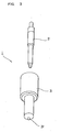
- Fig. 2 is a sectional view showing a rough structure of the fuel injection nozzle 1 according to the invention
- Fig. 3 is perspective view showing outer appearances of a needle valve 2 and the nozzle body 3 of the fuel injection nozzle 1.
- the high pressure DME fuel introduced from the inlet connector 53 into the inside of the fuel injection nozzle 1 through the filter 531 fills the inside of the nozzle body 3 through an oil storage chamber 32.
- the needle valve 2 is moved in a direction indicated by reference character B by the pressure of the DME fuel in the inside of the nozzle body 3 to open a valve, and the DME fuel is injected from a fuel injection hole 31 into the combustion chamber as indicated by an arrow of reference character C.
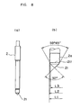
- Fig. 4 shows the needle valve 2 of the fuel injection nozzle 1 of the invention, in which Fig. 4(a) is a front view of the needle valve 2, and Fig. 4(b) is a front view in which a tip part 21 of the needle valve 2 is magnified.
- Fig. 5 is a sectional view in which a part of the fuel injection nozzle 1 is magnified and shown.
- the needle valve 2 has a substantially cylindrical shape, and the tip part 21 has a substantially right circular cone shape.
- the shape of the tip part 21 is set by a center diameter L3 for regulating a minimum flow path area of the fuel injection nozzle 1 at full lift, a seat diameter L2 of a seat part 211 coming in contact with a valve seat part 33 and blocking communication with the fuel injection hole 31, and a shaft diameter L1, and a tip part angle is abut 92 degrees.
- the center diameter L3 is set to ⁇ 2.5 mm
- the seat diameter L2 is set to ⁇ 3.0 mm
- the shaft diameter L1 is set to ⁇ 3.25 mm.
- the outer peripheral surface of the tip part 21 of the needle valve 2 urged in a state where the injection start pressure is regulated by the spring force of the nozzle spring 52 is seated on the valve seat part 33 of the nozzle body 3 as an inlet of the fuel injection hole 31 as shown in the drawing.
- the needle valve 2 is lifted by the pressure of a predetermined amount of high pressure DME fuel sent from an injection pump and the like, so that the tip part 21 of the needle valve 2 is separated from the valve seat part 33 to form a valve open state, and the DME fuel is sent from between the tip part 21 of the needle valve 2 and the valve seat part 33 to the fuel injection hole 31.
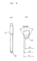
- the center diameter L3 is set to ⁇ 1.1 mm
- the seat diameter L2 is set to ⁇ 2.2 mm
- the shaft diameter L1 is set to ⁇ 3.25 mm.
- the total injection hole area of the fuel injection hole 31 formed in the nozzle body 3 is set to be smaller than the total injection hole area of the fuel injection hole 31 of the fuel injection nozzle 1 according to the invention.
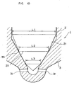
- Fig. 6 is a sectional view in which a part of the fuel injection nozzle 1 of the invention is magnified and shown, and shows a state where the needle valve 2 is lifted from the valve closed state shown in Fig. 5.
- the needle valve 2 is moved in the direction of the arrow denoted by reference character B and is lifted to a position of a maximum lift amount D, and at a time point when a full lift state occurs, an area of a portion where an interval between the tip part 21 of the needle valve 2 and the valve seat part 33 becomes minimum is a minimum flow path area d. Accordingly, a flow path area formed of the minimum flow path area d between the outer peripheral surface of the tip part 21 and the valve seat part 33 is a minimum flow path area. Besides, a maximum value of the fuel injection amount is determined by the total injection hole area of the fuel injection hole 31. Incidentally, in this embodiment, the maximum lift amount D at full lift of the fuel injection nozzle 1 is set to about 0.25 mm.
- the size of the fuel injection hole 31 of the nozzle body 3 of the fuel injection nozzle 1 according to the invention is formed to be larger, and by that, the total injection hole area is set to become approximately twice as large. This is because, as described before, in order to obtain the same engine output as the light oil fuel by using the DME fuel, a fuel injection amount larger than the light oil fuel becomes necessary. Accordingly, by setting the total injection hole area of the fuel injection hole 31 to be larger than that in the light oil fuel, the engine output comparable to the light oil fuel can be obtained by the DME fuel.
- the ratio L3/L2 of the center diameter L3 and the seat diameter L2 is set to be as large as about 0.833 in the fuel injection nozzle 1 of the invention, while it is set to 0.50 in the conventional fuel injection nozzle 1 of the diesel engine using light oil as fuel.
- the ratio L2/L1 of the seat diameter L2 and the shaft diameter L1 is set to be as large as about 0.92 in the fuel injection nozzle 1 of the invention, while it is set to about 0.68 in the conventional fuel injection nozzle 1 of the diesel engine using light oil as fuel.
- the minimum flow path area d of the fuel injection nozzle 1 of the invention at full lift is approximately twice as large as that of the conventional fuel injection nozzle 1 of the diesel engine using light oil as fuel.
- the ratio L3/L2 of the center diameter L3 and the seat diameter L2 is made 0.7 or higher and about 0.833 in this embodiment, and the ratio of L2/L1 of the seat diameter L2 and the shaft diameter L1 is made 0.85 or higher and about 0.92 in this embodiment, so that the minimum flow path area d at full lift can be made the area approximately twice as large.
- the fuel injection amount of the fuel injection nozzle 1 can be set to be approximately twice as large.
- Fig. 7 is a graph schematically showing a characteristic of a flow path area with respect to a lift amount of the needle valve 2 of the fuel injection nozzle 1 of the invention.
- the graph indicated by a solid line is the graph of the fuel injection nozzle 1 of the invention
- the graph indicated by an alternate long and short dash line is the graph of the fuel injection nozzle 1 of the diesel engine using light oil as fuel.
- An area denoted by reference character E1 is the total injection hole area of the fuel injection nozzle 1 of the diesel engine using light oil as fuel
- an area denoted by reference character E2 is the total injection hole area of the fuel injection nozzle 1 of the invention.
- the flow path area (vertical axis of the graph) is increased as shown in the drawing in proportion to the lift amount (horizontal axis of the graph) of the needle valve 2, and the flow path area characteristic of the needle valve 2 with respect to the lift amount is determined by the ratio L3/L2 of the center diameter L3 of the tip part 21 and the seat diameter L2, the ratio L2/L1 of the seat diameter L2 and the shaft diameter L1, and the total injection hole area of the fuel injection hole 31.
- the flow path area with respect to the lift amount of the needle valve 2 is larger than that of the fuel injection nozzle 1 of the light oil fuel at a substantially constant ratio.
- the total injection hole area E2 of the fuel injection nozzle 1 of the invention is set to the total injection hole area approximately twice as large as the total injection hole area E1 of the fuel injection nozzle of the diesel engine using light oil as fuel, so that the engine output characteristic comparable to the light oil fuel can be obtained by the DME fuel.
- the flow path area with respect to the lift amount of the needle valve 2 is also set so that the flow path area approximately twice as large can be obtained.
- the DME fuel approximately twice as large as the light oil with respect to the lift amount of the needle valve 2 can be supplied to the combustion chamber of the diesel engine, and according to that, the total injection hole area of the fuel injection hole 31 is also set to be approximately twice as large, so that the total injection hole area of the fuel injection hole 31 does not become a bottle neck.
- the existing diesel engine vehicle of the light oil fuel can be made to run as the diesel engine vehicle using DME as fuel at very low cost and easily.
- Fig. 8 shows another embodiment of a fuel injection nozzle for DME fuel according to the invention, in which Fig. 8A is a front view of a needle valve 2, and Fig. 8B is a front view in which a tip part of the needle valve 2 is magnified.
- a part (portion denoted by reference character 2a) of a shaft of the needle valve 2 is smaller than a shaft diameter L1 and has the same diameter as a seat diameter L2, an interval to a nozzle body 3 becomes wide by that, and a flow rate of DME fuel can be increased. Accordingly, it is possible to expect an effect that a diesel engine designed to use light oil as fuel can be driven at an engine output comparable to or higher than light oil by using DME fuel.
- the invention is not limited to the above embodiments, and various modifications can be made within the scope of the invention recited in the claims.
- the invention can be carried out also in a hole nozzle which is not a long stem type, and it is needless to say that those are also contained in the scope of the invention.
- the existing diesel engine vehicle of the light oil fuel can be made to run as the diesel engine vehicle using DME fuel as fuel without exchanging the whole diesel engine, and at very low cost and easily.
- the present invention can be used as a fuel injection nozzle for DME fuel in a diesel engine using DME (DiMethyl Ether) as fuel.
- DME DiMethyl Ether
Landscapes
- Engineering & Computer Science (AREA)
- Chemical & Material Sciences (AREA)
- Combustion & Propulsion (AREA)
- Mechanical Engineering (AREA)
- General Engineering & Computer Science (AREA)
- Chemical Kinetics & Catalysis (AREA)
- General Chemical & Material Sciences (AREA)
- Oil, Petroleum & Natural Gas (AREA)
- Fuel-Injection Apparatus (AREA)
Applications Claiming Priority (3)
| Application Number | Priority Date | Filing Date | Title |
|---|---|---|---|
| JP2002269786A JP3779250B2 (ja) | 2002-09-17 | 2002-09-17 | Dme燃料用燃料噴射ノズル、該dme燃料用燃料噴射ノズルを備えたディーゼルエンジン |
| JP2002269786 | 2002-09-17 | ||
| PCT/JP2003/011764 WO2004027256A1 (ja) | 2002-09-17 | 2003-09-16 | Dme燃料用燃料噴射ノズル及びdme燃料用燃料噴射ノズルを備えたディーゼルエンジン |
Publications (1)
| Publication Number | Publication Date |
|---|---|
| EP1550806A1 true EP1550806A1 (de) | 2005-07-06 |
Family
ID=32024817
Family Applications (1)
| Application Number | Title | Priority Date | Filing Date |
|---|---|---|---|
| EP03797608A Withdrawn EP1550806A1 (de) | 2002-09-17 | 2003-09-16 | Kraftstoffeinspritzd se f r dme-kraftstoff und dieselmotor mit der kraftstoffeinspritzd se f r dme-kraftstoff |
Country Status (7)
| Country | Link |
|---|---|
| US (1) | US7341205B2 (de) |
| EP (1) | EP1550806A1 (de) |
| JP (1) | JP3779250B2 (de) |
| KR (1) | KR20050057351A (de) |
| CN (1) | CN100447400C (de) |
| AU (1) | AU2003264440A1 (de) |
| WO (1) | WO2004027256A1 (de) |
Families Citing this family (11)
| Publication number | Priority date | Publication date | Assignee | Title |
|---|---|---|---|---|
| JP2007224746A (ja) * | 2006-02-21 | 2007-09-06 | Isuzu Motors Ltd | インジェクタノズル |
| DE102006043460A1 (de) * | 2006-09-15 | 2008-03-27 | Man Diesel Se | Verfahren zur Optimierung einer Einspritzdüse für eine Brennkraftmaschine |
| DE102007040910A1 (de) * | 2007-08-30 | 2009-03-05 | Bayerische Motoren Werke Aktiengesellschaft | Kraftstoffeinbringungseinrichtung und Verfahren zum Betreiben derselben |
| CN102182599A (zh) * | 2011-03-30 | 2011-09-14 | 潍柴动力股份有限公司 | 一种二甲醚发动机燃油供给系统及其喷油器 |
| WO2016121475A1 (ja) * | 2015-01-30 | 2016-08-04 | 日立オートモティブシステムズ株式会社 | 燃料噴射弁 |
| US9964086B2 (en) * | 2015-07-01 | 2018-05-08 | Ford Global Technologies, Llc | Fuel injector and method |
| KR20170017484A (ko) | 2015-08-07 | 2017-02-15 | 주식회사 신원미크론 | 고유량 디젤엔진의 연료분사노즐 |
| US11125147B2 (en) | 2019-06-11 | 2021-09-21 | Caterpillar Inc. | Prechamber ignition system having hydraulically actuated piston |
| US11506381B2 (en) * | 2020-05-15 | 2022-11-22 | Zeeco, Inc. | Plug-resistant burner tip and method |
| JP7724058B2 (ja) * | 2020-12-03 | 2025-08-15 | 株式会社ジャパンエンジンコーポレーション | 燃料噴射弁および舶用内燃機関 |
| US12449122B2 (en) | 2022-11-14 | 2025-10-21 | Zeeco, Inc. | Free-jet burner and method for low CO2, NOx, and CO emissions |
Family Cites Families (11)
| Publication number | Priority date | Publication date | Assignee | Title |
|---|---|---|---|---|
| JPH0388957A (ja) * | 1989-08-22 | 1991-04-15 | New Zealand Government | 圧縮点火エンジンの燃料供給装置及びその制御装置 |
| US5485818A (en) * | 1995-02-22 | 1996-01-23 | Navistar International Transportation Corp. | Dimethyl ether powered engine |
| JPH09250423A (ja) * | 1996-03-18 | 1997-09-22 | Keehin:Kk | 電磁式燃料噴射弁 |
| CN1169507A (zh) * | 1996-06-21 | 1998-01-07 | 株式会社杰克赛尔 | 喷油器 |
| US6109536A (en) * | 1998-05-14 | 2000-08-29 | Caterpillar Inc. | Fuel injection system with cyclic intermittent spray from nozzle |
| JP2000120493A (ja) * | 1998-10-15 | 2000-04-25 | Nkk Corp | ジメチルエーテル用ディーゼル機関 |
| RU2205861C1 (ru) * | 1999-07-01 | 2003-06-10 | Хальдор Топсёэ А/С | Непрерывная дегидратация спирта до простого эфира и воды, применяемых как топливо для дизельных двигателей |
| JP2001107826A (ja) * | 1999-10-12 | 2001-04-17 | Toyota Motor Corp | 筒内噴射式内燃機関の燃料噴射ノズル |
| US6640754B1 (en) * | 2000-09-14 | 2003-11-04 | Yamaha Hatsudoki Kabushiki Kaisha | Ignition timing system for homogeneous charge compression engine |
| US6439192B1 (en) * | 2000-10-24 | 2002-08-27 | Westport Research Inc. | Gaseous and liquid fuel injection valve with concentric needles |
| US20020152985A1 (en) * | 2001-04-20 | 2002-10-24 | Wolff Peter U. | System, apparatus including on-board diagnostics, and methods for improving operating efficiency and durability of compression ignition engines |
-
2002
- 2002-09-17 JP JP2002269786A patent/JP3779250B2/ja not_active Expired - Lifetime
-
2003
- 2003-09-16 EP EP03797608A patent/EP1550806A1/de not_active Withdrawn
- 2003-09-16 US US10/528,083 patent/US7341205B2/en not_active Expired - Fee Related
- 2003-09-16 WO PCT/JP2003/011764 patent/WO2004027256A1/ja not_active Ceased
- 2003-09-16 KR KR1020057004467A patent/KR20050057351A/ko not_active Ceased
- 2003-09-16 AU AU2003264440A patent/AU2003264440A1/en not_active Abandoned
- 2003-09-16 CN CNB038220598A patent/CN100447400C/zh not_active Expired - Fee Related
Non-Patent Citations (1)
| Title |
|---|
| See references of WO2004027256A1 * |
Also Published As
| Publication number | Publication date |
|---|---|
| US20050252996A1 (en) | 2005-11-17 |
| CN100447400C (zh) | 2008-12-31 |
| CN1682029A (zh) | 2005-10-12 |
| KR20050057351A (ko) | 2005-06-16 |
| US7341205B2 (en) | 2008-03-11 |
| AU2003264440A1 (en) | 2004-04-08 |
| JP3779250B2 (ja) | 2006-05-24 |
| WO2004027256A1 (ja) | 2004-04-01 |
| JP2004108195A (ja) | 2004-04-08 |
Similar Documents
| Publication | Publication Date | Title |
|---|---|---|
| EP1550806A1 (de) | Kraftstoffeinspritzd se f r dme-kraftstoff und dieselmotor mit der kraftstoffeinspritzd se f r dme-kraftstoff | |
| KR20010074482A (ko) | 점화 제어 방식의 직접 분사형 내연 기관 | |
| JPWO1996036808A1 (ja) | 筒内噴射式内燃機関 | |
| KR20020050146A (ko) | 냅 각도가 작은 직접 분사식 내연 기관 및 이를 사용하기위한 방법 | |
| WO1987000583A1 (en) | Direct fuel injection by compressed gas | |
| US6035823A (en) | Spark-ignition type engine | |
| FR3047043A1 (fr) | Moteur a combustion interne a taux de compression variable avec deux zones de melange, notamment pour vehicule automobile et procede d'injection pour un tel moteur. | |
| US5724937A (en) | Internal combustion engine with direct fuel injection | |
| US9664160B2 (en) | Vehicular high pressure direct injection type injector with valve seat body for fuel-atomization | |
| CN1087057C (zh) | 具有主动引导头部的活塞及相应的燃烧室 | |
| JP6025873B2 (ja) | 特に自動車用の内燃機関及びそのような内燃機関の作動方法 | |
| JPH1037836A (ja) | 点火装置 | |
| US5105781A (en) | Air-compressing internal combustion engine with self-ignition, with a main combustion space and an insert adjoining the latter, accommodated in the cylinder head and having an antechamber | |
| RU2002110093A (ru) | Клапанная форсунка для впрыскивания топлива | |
| RU2027061C1 (ru) | Распылитель форсунки для двигателя внутреннего сгорания | |
| CN103089509A (zh) | 多液囊喷射器 | |
| US20090114185A1 (en) | Internal-combustion engine, notably of direct injection type, with a piston provided with a bowl comprising a teat | |
| JP2005180253A (ja) | 液化ガス燃料用燃料噴射ノズル、該液化ガス燃料用燃料噴射ノズルを備えたディーゼルエンジン | |
| US20120132728A1 (en) | Injector for vehicles | |
| US6676040B2 (en) | Variable swirl type GDI injector | |
| JP3748116B2 (ja) | 燃料噴射装置 | |
| JP2021113520A (ja) | ポート噴射式内燃機関 | |
| US20250059940A1 (en) | A fuel gas injection arrangement and a hydrogen internal combustion engine | |
| CN213981014U (zh) | 用于内燃发动机的燃烧室的燃料喷射喷嘴和内燃发动机 | |
| KR100240398B1 (ko) | 차량용 인젝터 |
Legal Events
| Date | Code | Title | Description |
|---|---|---|---|
| PUAI | Public reference made under article 153(3) epc to a published international application that has entered the european phase |
Free format text: ORIGINAL CODE: 0009012 |
|
| 17P | Request for examination filed |
Effective date: 20050408 |
|
| AK | Designated contracting states |
Kind code of ref document: A1 Designated state(s): AT BE BG CH CY CZ DE DK EE ES FI FR GB GR HU IE IT LI LU MC NL PT RO SE SI SK TR |
|
| AX | Request for extension of the european patent |
Extension state: AL LT LV MK |
|
| DAX | Request for extension of the european patent (deleted) | ||
| STAA | Information on the status of an ep patent application or granted ep patent |
Free format text: STATUS: THE APPLICATION IS DEEMED TO BE WITHDRAWN |
|
| 18D | Application deemed to be withdrawn |
Effective date: 20100401 |