EP1549776B1 - Abkühlvorrichtung für stahlband - Google Patents
Abkühlvorrichtung für stahlband Download PDFInfo
- Publication number
- EP1549776B1 EP1549776B1 EP03798394A EP03798394A EP1549776B1 EP 1549776 B1 EP1549776 B1 EP 1549776B1 EP 03798394 A EP03798394 A EP 03798394A EP 03798394 A EP03798394 A EP 03798394A EP 1549776 B1 EP1549776 B1 EP 1549776B1
- Authority
- EP
- European Patent Office
- Prior art keywords
- steel strip
- cooling
- nozzle
- nozzles
- cooling device
- Prior art date
- Legal status (The legal status is an assumption and is not a legal conclusion. Google has not performed a legal analysis and makes no representation as to the accuracy of the status listed.)
- Expired - Lifetime
Links
Images


Classifications
-
- C—CHEMISTRY; METALLURGY
- C21—METALLURGY OF IRON
- C21D—MODIFYING THE PHYSICAL STRUCTURE OF FERROUS METALS; GENERAL DEVICES FOR HEAT TREATMENT OF FERROUS OR NON-FERROUS METALS OR ALLOYS; MAKING METAL MALLEABLE, e.g. BY DECARBURISATION OR TEMPERING
- C21D9/00—Heat treatment, e.g. annealing, hardening, quenching or tempering, adapted for particular articles; Furnaces therefor
- C21D9/52—Heat treatment, e.g. annealing, hardening, quenching or tempering, adapted for particular articles; Furnaces therefor for wires; for strips ; for rods of unlimited length
- C21D9/54—Furnaces for treating strips or wire
- C21D9/56—Continuous furnaces for strip or wire
- C21D9/573—Continuous furnaces for strip or wire with cooling
-
- C—CHEMISTRY; METALLURGY
- C21—METALLURGY OF IRON
- C21D—MODIFYING THE PHYSICAL STRUCTURE OF FERROUS METALS; GENERAL DEVICES FOR HEAT TREATMENT OF FERROUS OR NON-FERROUS METALS OR ALLOYS; MAKING METAL MALLEABLE, e.g. BY DECARBURISATION OR TEMPERING
- C21D1/00—General methods or devices for heat treatment, e.g. annealing, hardening, quenching or tempering
- C21D1/56—General methods or devices for heat treatment, e.g. annealing, hardening, quenching or tempering characterised by the quenching agents
- C21D1/613—Gases; Liquefied or solidified normally gaseous material
-
- C—CHEMISTRY; METALLURGY
- C21—METALLURGY OF IRON
- C21D—MODIFYING THE PHYSICAL STRUCTURE OF FERROUS METALS; GENERAL DEVICES FOR HEAT TREATMENT OF FERROUS OR NON-FERROUS METALS OR ALLOYS; MAKING METAL MALLEABLE, e.g. BY DECARBURISATION OR TEMPERING
- C21D1/00—General methods or devices for heat treatment, e.g. annealing, hardening, quenching or tempering
- C21D1/62—Quenching devices
- C21D1/667—Quenching devices for spray quenching
Definitions
- the present invention relates to a device for cooling a steel strip which is traveling continuously in, for example, a continuous annealing facility, a continuous hot dip galvanizing facility, a color coating line, a stainless steel pickling and annealing line, or the like, used for processing the steel strip.
- a roll cooling method has the following problem.
- a steel strip may not remain flat when it passes through a continuous annealing furnace. Therefore, when a steel strip has contact with a cooling roll, some portions of the steel strip may not contact the cooling roll. In that case, the non-contacting portions make the cooling of the steel strip uneven along the width direction thereof and thus cause the shape of the steel strip to deform.
- a means is required for flattening a steel strip before it has contact with a cooling roll.
- the means causes the equipment cost to increase.
- a cooling method that uses gas as a cooling medium is put into practical use and achieves various results.
- a cooling rate is lower in comparison with aforementioned water cooling and roll cooling methods, a steel strip can be cooled comparatively evenly along the width direction thereof.
- a cooling rate is raised by bringing the tips of nozzles for ejecting gas as close to a steel strip as possible and thus raising a heat transfer coefficient; and a cooling rate is raised by increasing the concentration of hydrogen gas as a cooling medium and thus raising a heat transfer coefficient.
- JP-A-62116724 As a method of raising a heat transfer coefficient by bringing the tips of nozzles for ejecting gas as close to a steel strip as possible, there is a technology disclosed in JP-A-62116724. In the technology, an efficient cooling is made possible by reducing distance between the tips of nozzles and a steel strip.
- the patent publication discloses that: the length of protruding nozzles being provided in a cooling gas chamber and protruding from the surface of the wall of the cooling gas chamber is adjusted to 100 mm - Z or longer; a space is provided from which gas being ejected from the protruding nozzles and hitting a steel strip escapes behind the wall; by so doing, the retention of ejected gas on the surface of the steel strip lessens; and thus the uniformity of cooling along the width direction of the steel strip improves.
- Z indicates the distance between the tip of a nozzle and a steel strip.
- the patent publication also discloses an experiment carried out for clarifying an optimum heat transfer coefficient with the protruding length of nozzles varied from 50 mm - Z to 200 mm - Z. Further, the patent publication proposes a cooling device that has an efficient cooling capacity on the basis of the experiment. By the cooling device, a heat transfer coefficient, that has usually been 100 kcal/m 2 h°C, is improved to 400 kcal/m 2 h°C.
- a technology wherein the concentration of hydrogen gas is raised and thus a steel strip is rapidly cooled is disclosed in Japanese Unexamined Patent Publication No. H9-235626.
- the technology is the one that secures a high cooling rate by blowing a cooling gas having a hydrogen concentration in the range from 30 to 60% onto a steel strip at a blowing rate in the range from 100 to 150 m/sec.
- a cooling gas having a hydrogen concentration in the range from 30 to 60% onto a steel strip at a blowing rate in the range from 100 to 150 m/sec In this manner, concrete technologies for adopting hydrogen gas are being developed and are ready to be put into practical use.
- the volume of the gas blown onto a steel strip is required to increase and also a gas pressure sufficient for ejecting the gas through nozzles at a blowing rate in the range from 100 to 150 m/sec. must also to be secured.
- a cooling device generally adopted is a circulation-type cooling device wherein a cooling medium having been blown onto a steel strip is circulated through a duct and blown again onto the steel strip.
- a cooling medium having been blown onto a steel strip is discharged into a furnace and sucked through a suction duct installed at the furnace body with a circulation blower.
- a heat exchanger for cooling the cooling medium, that has been blown onto the steel strip and has been heated, to a blowing temperature so that the steel strip may be cooled with those devices while the cooling medium is circulated.
- the highest pressure in such a circulation system is a pressure required when a cooling medium is ejected from nozzles and it has been desired to reduce the pressure drop, to the utmost, at the nozzles.
- Fig. 1 is a sectional side view of cooling devices in continuous annealing facilities to which the present invention is applied
- Fig. 2 a view taken on line A-A in Fig. 1
- Fig. 3 a view showing the details of a nozzle according to the present invention
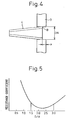
- Fig. 4 a view showing knacks for attaching a nozzle according to the present invention
- Fig. 5 a graph showing resistance coefficients of nozzles
- Fig. 6 a schematic illustration showing an example of applying cooling devices according to the present invention to a continuous coating line
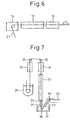
- Figs. 7 and 8 schematic illustrations each of which showing an example of applying the present invention to cooling devices for cooling a steel strip after being galvanized in continuous hot dip galvanizing facilities.
- a pair of cooling devices 2 that eject gas are installed between upper and lower rolls 9 and 11, said rolls conveying a steel strip 12, so as to be opposed to the surfaces of said steel strip 12, and said paired cooling devices 2 are arranged at plural levels along the traveling direction of said steel strip 12. Further, holddown rolls 10 for preventing a flutter of said steel strip are provided above and under said paired cooling devices 2 so as to grasp said steel strip in between the rolls.
- a cooling medium containing cooling gas is a mixed gas composed of N 2 , H 2 and other inert gases and it is preferable that the concentration of H 2 is in the range from 0 to 100% with the balance consisting of N 2 and other inert gases.
- a blown gas is drawn in from a gas suction port provided at a furnace body 1, passes through an inlet duct 5, a heat exchanger 6, a circulation blower 7 and an outlet duct 8, and is blown again onto said steel strip 12 through nozzles provided at the surfaces of cooling chambers 3, the surfaces of said cooling chambers 3 being opposed to said steel strip 12, by using a circulatory system connected to said cooling chambers 3 in said furnace body.
- a gas blown onto a steel strip 12 in a furnace is circulated and reused.
- a cooling device 2 is composed of a cooling chamber 3 and protruding nozzles 4 provided at the surface of said cooling chamber 3, the surface of said cooling chamber 3 being opposed to a steel strip 12.
- Each of the protruding nozzles 4 is selected so that the ratio (D/d) of the inner diameter at the nozzle foot B side D to the inner diameter at the nozzle tip A side d falls within the range from 1.5 to 3.0. Further, the protruding nozzles are arranged so that the total aperture area of the nozzle tips accounts for 2 to 4% of the surface area of a cooling chamber.
- D is the inner diameter at the nozzle foot B side (here, the nozzle foot B side means the side at which a nozzle is attached to a cooling chamber 3), DO the outer diameter at the nozzle foot B side, d the inner diameter at the nozzle tip A side, L the total length of a nozzle, and DN the outer diameter of a nozzle at a position located in the range of (nozzle total length L) - (10 ⁇ 3 mm), in other words, the range of 10 ⁇ 3 mm away from a nozzle foot B side in the direction of the nozzle tip A side.
- a nozzle 4 is conical in shape and therefore made by rolling an SUS (stainless steel) plate.
- a nozzle may be made by drawing a tube, cutting, or casting. The experiment was carried out with nozzles having a total length of 200 mm and various ratios D/d. When the nozzle total length L is less than 200 mm, the minimum distance between the nozzle tip and the steel strip surface is limited to 50 mm. However, when the nozzle total length is not less than 200 mm, the minimum distance between the nozzle tip and the steel strip surface can be shortened to 30 mm.
- a hole having a diameter DN is provided at a surface of a cooling chamber 3, the surface being opposed to a steel strip 12.
- the number of holes is determined so that the total aperture area may account for 2 to 4% of the surface area of the cooling chamber.
- the diameter DN is set so as to equal the diameter of the nozzle at a position located in the range of 10 ⁇ 3 mm away from the nozzle foot B in the direction of the nozzle tip A side.
- a hole of a diameter DN is drilled at the surface of a cooling chamber 3.
- a nozzle having an outer diameter DO at the nozzle foot B is inserted in the hole and attached to the hole of the cooling chamber 3 as shown in Fig. 4 with a punch (not shown in the figure).
- the nozzle is attached to the hole, it should be ensured that the nozzle foot B does not protrude from the inner surface of the cooling chamber as shown in Fig. 4.
- the nozzle is inserted so that the nozzle foot B may be located 10 mm in depth from the inner surface of the cooling chamber 3. This is because that when the nozzle total length is less than 200 mm, the gas jetted from the nozzle stagnates on the steel strip surface and causes flattering.
- the nozzle foot inner diameter D is enlarged with a tube expander from the foot B side of the punched nozzle 4 and the nozzle is bonded by pressure to the inside of the hole having been provided at the cooling chamber 3 and having the diameter DN.
- the reason for limiting the position where the diameter DN is defined as described above is that: when the position exceeds the upper limit (10 + 3 mm), a nozzle is hard to insert; and, when the position is shorter than the lower limit, on the other hand, the accuracy of a nozzle attachment is inferior.
- the nozzle is fixed so that the tip of the nozzle foot side may be depressed in the hole from the inner surface of the cooling chamber 3 for the purpose of reducing the resistance coefficient of the nozzle.
- the tip of the nozzle foot side may be on the same surface as the inner surface of the cooling chamber 3 as long as the resistance coefficient of the nozzle is reduced.
- the pressure losses of the nozzles made as described above were measured with an experimental apparatus and the resistance coefficient of each of the nozzles was calculated.
- the results are shown in Fig. 5. It has been clarified that the resistance coefficient is small when D/d is in the range from 1.5 to 3.0 and the smallest when D/d is 2.0 or so in comparison with the resistance coefficient obtained when D/d is 1.0, which is the case of a conventional straight nozzle. Therefore, the resistance coefficient of a nozzle according to the present invention decreases by about 30% from that of a conventional straight nozzle.
- Fig. 6 shows the arrangement of a coater and a drying and baking furnace in a continuous coating line.
- the surface of a steel strip S1 is coated with paint in a coater 14 and then dried and baked with a prescribed temperature transition in a drying and baking furnace 15. Successively, the steel strip is cooled to a temperature close to room temperature in a cooling device assembly 16.
- a cooling device assembly 16 the surface quality of a coated paint is secured by employing air cooling at the former stage and a rapid cooling has been secured by employing water cooling at the latter stage.
- Fig. 7 shows an example of applying a cooling device assembly in which nozzles according to the present invention are used in a cooling device assembly located at the rear of a plated layer alloying treatment apparatus in continuous hot dip galvanizing facilities.
- a steel strip S2 is introduced into a plating pot 19 through a turndown roll 18 provided in a turndown section 17.
- the steel strip S2 is pulled upward through a sink roll 20, and, after the thickness of the plated layer of the steel strip S2 is adjusted to a prescribed thickness in a plating apparatus 21, it is heated to an alloying treatment temperature in an alloying heater 22 and successively retained in a retention furnace 23.
- the steel strip S2 having been subjected to alloying treatment is cooled in a cooling device assembly 24 and another cooling device assembly 27 provided in the down pass, and is conveyed to a dip-cooling apparatus 28 for final cooling.
- a cooling device assembly in which nozzles according to the present invention are used with the cooling device assemblies 24 and 27 not only cooling efficiency can be raised and thus the entire height of the alloying furnace can be lowered, but also a steel strip S2 can be rapidly cooled after being subjected to alloying treatment and thus a sound alloyed layer can be obtained.
- Fig. 8 shows an example of applying a cooling device assembly in which tapered nozzles, each having a round aperture according to the present invention, are used in a cooling device assembly located at the rear of a plating apparatus likewise in a continuous hot dip galvanizing facility.
- a steel strip S2 after the thickness of the plating layer of the steel strip is adjusted to a prescribed thickness in a plating apparatus 21, is cooled in a cooling device assembly 24 and another cooling device assembly 27 provided in the down pass, and is conveyed to a dip-cooling apparatus 28 for final cooling.
- Fig. 9 shows an example of continuous annealing and pickling facilities for stainless steel strips.
- a stainless steel strip S3 is heated and soaked at a prescribed annealing temperature in a heating zone 29 and then is cooled at a prescribed cooling rate to a final temperature in a cooling zone 30.
- scales formed on the surfaces of the stainless steel strip S3 owing to rolls arranged on the upper and lower sides of the stainless steel strip S3 are removed in a descaling apparatus 31. Thereafter, the stainless steel strip S3 is introduced into a pickling tank 32.
- the present invention provides a cooling device for a steel strip, the cooling device allowing the ejection velocity of a nozzle to increase, the resistance coefficient of a nozzle to decrease and, thus, a high cooling rate to be secured, and, by so doing, a circulatory system to be downsized; and makes it possible to provide a cooling device for a steel strip, the cooling device enabling the distortion of nozzles caused by welding to be eliminated and fabrication accuracy to be improved by employing a pressure bonded structure instead of a conventional welded structure.
Landscapes
- Chemical & Material Sciences (AREA)
- Engineering & Computer Science (AREA)
- Materials Engineering (AREA)
- Thermal Sciences (AREA)
- Crystallography & Structural Chemistry (AREA)
- Mechanical Engineering (AREA)
- Physics & Mathematics (AREA)
- Metallurgy (AREA)
- Organic Chemistry (AREA)
- Heat Treatment Of Strip Materials And Filament Materials (AREA)
- Coating With Molten Metal (AREA)
- Details Or Accessories Of Spraying Plant Or Apparatus (AREA)
- Nozzles (AREA)
- Heat Treatments In General, Especially Conveying And Cooling (AREA)
Claims (6)
- Abkühlvorrichtung (2) für Stahlband, wobei die Abkühlvorrichtung mit mehreren Düsen (4) versehen ist, die von der Oberfläche der Kühlkammer (3) vorstehen, und ein durchlaufendes Stahlband durch Ausstoßen eines Kühlmittels durch die Düsen abgekühlt wird, wobei der Abstand zwischen den Spitzen der Düsen (A) und den Oberflächen des Stahlbandes im Bereich von 50 bis 100 mm gehalten wird, dadurch gekennzeichnet, dass die Gesamtdüsenlänge weniger als 200 mm beträgt, und D/d der Blasdüsen den Ausdruck 1,5 ≤ D/d ≤ 3,0 erfüllt, wobei d den Innendurchmesser an einer Düsenspitze (A) auf der Stahlbandseite und D den Innendurchmesser an einem Düsenfuß (B) auf der Kühlkammerseite darstellt.
- Abkühlvorrichtung (2) für Stahlband, wobei die Abkühlvorrichtung mit mehreren Düsen (4) versehen ist, die von der Oberfläche der Kühlkammern vorstehen, und ein durchlaufendes Stahlband durch Ausstoßen eines Kühlmittels durch die Düsen abgekühlt wird, wobei der Abstand zwischen den Spitzen der Düsen (A) und den Oberflächen des Stahlbandes im Bereich von 30 bis 100 mm gehalten wird, dadurch gekennzeichnet, dass die Gesamtdüsenlänge nicht weniger als 200 mm beträgt, und D/d der Blasdüsen den Ausdruck 1,5 ≤ D/d ≤ 3,0 erfüllt, wobei d den Innendurchmesser an einer Düsenspitze (A) auf der Stahlbandseite und D den Innendurchmesser an einem Düsenfuß (B) auf der Kühlkammerseite darstellt.
- Abkühlvorrichtung für Stahlband gemäß Anspruch 1 oder 2, dadurch gekennzeichnet, dass die Düsen (4) durch Befestigen der Füße (B) der Düsen (4), mittels Rohrdehnungverbindung, in Passlöcher angebracht sind, die in einer Kühlkammer (3) vorgesehen sind.
- Abkühlvorrichtung für Stahlband gemäß einem der Ansprüche 1 bis 3, dadurch gekennzeichnet, dass die Durchmesser der Passlöcher, die in der Kühlkammer (3) vorgesehen sind, den Außendurchmesser der Düsen (4) an einer Position im Bereich von (Gesamtdüsenlänge L - 10 mm (10 mm entfernt vom Düsenfuß in Richtung Düsenspitze)) ± 3 mm entsprechen.
- Abkühlvorrichtung für Stahlband gemäß einem der Ansprüche 1 bis 4, dadurch gekennzeichnet, dass die Düsen (4) so befestigt sind, dass der Fuß der Düsen nicht von der Innenfläche der Kühlkammer (3) vorsteht.
- Abkühlvorrichtung für Stahlband gemäß einem der Ansprüche 1 bis 5, dadurch gekennzeichnet, dass das Kühlmittel der Abkühlvorrichtung (2) ein Mischgas, bestehend aus N2, H2, und anderen Inertgasen ist, und die H2-Konzentration im Bereich von 0 bis 100 % liegt, Rest bestehend aus N2 oder anderen Inertgasen.
Applications Claiming Priority (5)
| Application Number | Priority Date | Filing Date | Title |
|---|---|---|---|
| JP2002284302 | 2002-09-27 | ||
| JP2002284302 | 2002-09-27 | ||
| JP2003172695 | 2003-06-17 | ||
| JP2003172695A JP4331982B2 (ja) | 2002-09-27 | 2003-06-17 | 鋼帯の冷却装置 |
| PCT/JP2003/011522 WO2004029305A1 (en) | 2002-09-27 | 2003-09-09 | Cooling device for steel strip |
Publications (2)
| Publication Number | Publication Date |
|---|---|
| EP1549776A1 EP1549776A1 (de) | 2005-07-06 |
| EP1549776B1 true EP1549776B1 (de) | 2006-11-29 |
Family
ID=32044646
Family Applications (1)
| Application Number | Title | Priority Date | Filing Date |
|---|---|---|---|
| EP03798394A Expired - Lifetime EP1549776B1 (de) | 2002-09-27 | 2003-09-09 | Abkühlvorrichtung für stahlband |
Country Status (8)
| Country | Link |
|---|---|
| EP (1) | EP1549776B1 (de) |
| JP (1) | JP4331982B2 (de) |
| KR (1) | KR100664002B1 (de) |
| AU (1) | AU2003258836A1 (de) |
| BR (1) | BR0314758B1 (de) |
| CA (1) | CA2500271C (de) |
| DE (1) | DE60310106T2 (de) |
| WO (1) | WO2004029305A1 (de) |
Cited By (1)
| Publication number | Priority date | Publication date | Assignee | Title |
|---|---|---|---|---|
| US10927426B2 (en) | 2016-04-05 | 2021-02-23 | Nippon Steel Corporation | Cooling equipment for continuous annealing furnace |
Families Citing this family (7)
| Publication number | Priority date | Publication date | Assignee | Title |
|---|---|---|---|---|
| JP4537875B2 (ja) * | 2005-03-30 | 2010-09-08 | 新日本製鐵株式会社 | 鋼帯の冷却装置 |
| US7968046B2 (en) | 2005-08-01 | 2011-06-28 | Ebner Industrieofenbau Ges.M.B.H | Apparatus for cooling a metal strip |
| AT502239B1 (de) * | 2005-08-01 | 2007-07-15 | Ebner Ind Ofenbau | Vorrichtung zum kühlen eines metallbandes |
| JP4901276B2 (ja) * | 2006-04-10 | 2012-03-21 | 新日本製鐵株式会社 | 鋼帯の冷却装置 |
| FR2919877B1 (fr) * | 2007-08-10 | 2009-10-09 | Siemens Vai Metals Tech Sas | Dispositif de refroidissement apres galvanisation d'un produit en bande |
| MX2021005696A (es) * | 2018-11-14 | 2021-07-15 | Druids Process Tech S L | Dispositivo y procedimiento de enfriamiento para enfriar un alambre e instalacion de procesado de alambre correspondiente. |
| KR20210016840A (ko) * | 2019-08-05 | 2021-02-17 | 주식회사 포스코 | 스트립의 진동 감쇠 장치 |
Family Cites Families (5)
| Publication number | Priority date | Publication date | Assignee | Title |
|---|---|---|---|---|
| US4750715A (en) * | 1985-07-09 | 1988-06-14 | Mitsubishi Jukogyo Kabushiki Kaisha | Apparatus for cooling steel belt |
| JPS62116724A (ja) * | 1985-11-15 | 1987-05-28 | Nippon Steel Corp | 連続焼鈍炉におけるストリツプ冷却装置 |
| US5611151A (en) | 1994-06-10 | 1997-03-18 | Busch Co. | Strip cooling, heating, wiping or drying apparatus and associated method |
| TW420718B (en) * | 1995-12-26 | 2001-02-01 | Nippon Steel Corp | Primary cooling method in continuously annealing steel strip |
| FR2796139B1 (fr) * | 1999-07-06 | 2001-11-09 | Stein Heurtey | Procede et dispositif de suppression de la vibration des bandes dans des zones de soufflage de gaz, notamment des zones de refroidissement |
-
2003
- 2003-06-17 JP JP2003172695A patent/JP4331982B2/ja not_active Expired - Fee Related
- 2003-09-09 DE DE60310106T patent/DE60310106T2/de not_active Expired - Lifetime
- 2003-09-09 BR BRPI0314758-4A patent/BR0314758B1/pt active IP Right Grant
- 2003-09-09 CA CA2500271A patent/CA2500271C/en not_active Expired - Lifetime
- 2003-09-09 AU AU2003258836A patent/AU2003258836A1/en not_active Abandoned
- 2003-09-09 WO PCT/JP2003/011522 patent/WO2004029305A1/en not_active Ceased
- 2003-09-09 KR KR1020057005321A patent/KR100664002B1/ko not_active Expired - Fee Related
- 2003-09-09 EP EP03798394A patent/EP1549776B1/de not_active Expired - Lifetime
Cited By (1)
| Publication number | Priority date | Publication date | Assignee | Title |
|---|---|---|---|---|
| US10927426B2 (en) | 2016-04-05 | 2021-02-23 | Nippon Steel Corporation | Cooling equipment for continuous annealing furnace |
Also Published As
| Publication number | Publication date |
|---|---|
| AU2003258836A1 (en) | 2004-04-19 |
| KR20050090370A (ko) | 2005-09-13 |
| DE60310106D1 (de) | 2007-01-11 |
| WO2004029305A1 (en) | 2004-04-08 |
| DE60310106T2 (de) | 2007-06-21 |
| JP2004162167A (ja) | 2004-06-10 |
| EP1549776A1 (de) | 2005-07-06 |
| CA2500271C (en) | 2011-02-22 |
| CA2500271A1 (en) | 2004-04-08 |
| BR0314758A (pt) | 2005-07-26 |
| AU2003258836A8 (en) | 2004-04-19 |
| BR0314758B1 (pt) | 2011-04-05 |
| KR100664002B1 (ko) | 2007-01-03 |
| JP4331982B2 (ja) | 2009-09-16 |
Similar Documents
| Publication | Publication Date | Title |
|---|---|---|
| EP1935522B1 (de) | Umkehrbare walzrollen mit abkühlanlage und entsprechendes verfahren zum kühlen stahlplatte oder -bleches | |
| RU2745923C1 (ru) | Установка и способ для производства толстого стального листа | |
| EP1549776B1 (de) | Abkühlvorrichtung für stahlband | |
| KR100293139B1 (ko) | 가스분출류에 의한 강밴드 열처리 장치 | |
| JP4319254B2 (ja) | 押し出し成形プロファイルを冷却する装置 | |
| WO1997024468A1 (en) | Primary cooling method in continuously annealing steel strip | |
| EP2495343B1 (de) | Gasstrahlkühlungsvorrichtung für einen kontinuierlichen glühofen | |
| US6913659B2 (en) | Rapid cooling device for steel band in continuous annealing equipment | |
| TWI569898B (zh) | Manufacture method and manufacturing equipment of thick steel plate | |
| JP4332017B2 (ja) | 連続焼鈍炉の鋼帯の冷却装置 | |
| CN100402674C (zh) | 钢带冷却装置 | |
| JP4537875B2 (ja) | 鋼帯の冷却装置 | |
| JP4901276B2 (ja) | 鋼帯の冷却装置 | |
| KR100362671B1 (ko) | 합금화 용융아연도금강판의 냉각방법 및이에 이용되는 냉각장치 | |
| JP5482705B2 (ja) | 冷却装置及び冷却方法 | |
| JP5114655B2 (ja) | ルーズコイルの冷却設備及び冷却方法 | |
| JP3739934B2 (ja) | 薄鋼板の均一冷却方法 | |
| JP2006144104A (ja) | 溶融亜鉛メッキ用鋼板の連続焼鈍装置及び連続焼鈍方法 | |
| JP6904370B2 (ja) | ガスジェット冷却装置及び冷却方法 | |
| JP2006274365A (ja) | 鋼帯の冷却装置 | |
| JP3343021B2 (ja) | 電気錫めっき鋼帯の冷却装置 | |
| JPH07290136A (ja) | H形鋼の冷却方法および装置 | |
| JP4426886B2 (ja) | 連続式溶融めっきラインにおける焼鈍設備 | |
| JPH0919711A (ja) | 高温鋼材の冷却装置 | |
| JPS6157894B2 (de) |
Legal Events
| Date | Code | Title | Description |
|---|---|---|---|
| PUAI | Public reference made under article 153(3) epc to a published international application that has entered the european phase |
Free format text: ORIGINAL CODE: 0009012 |
|
| 17P | Request for examination filed |
Effective date: 20050426 |
|
| AK | Designated contracting states |
Kind code of ref document: A1 Designated state(s): AT BE BG CH CY CZ DE DK EE ES FI FR GB GR HU IE IT LI LU MC NL PT RO SE SI SK TR |
|
| AX | Request for extension of the european patent |
Extension state: AL LT LV MK |
|
| RBV | Designated contracting states (corrected) |
Designated state(s): DE FR GB |
|
| DAX | Request for extension of the european patent (deleted) | ||
| GRAP | Despatch of communication of intention to grant a patent |
Free format text: ORIGINAL CODE: EPIDOSNIGR1 |
|
| GRAS | Grant fee paid |
Free format text: ORIGINAL CODE: EPIDOSNIGR3 |
|
| GRAA | (expected) grant |
Free format text: ORIGINAL CODE: 0009210 |
|
| AK | Designated contracting states |
Kind code of ref document: B1 Designated state(s): DE FR GB |
|
| REG | Reference to a national code |
Ref country code: GB Ref legal event code: FG4D |
|
| REF | Corresponds to: |
Ref document number: 60310106 Country of ref document: DE Date of ref document: 20070111 Kind code of ref document: P |
|
| ET | Fr: translation filed | ||
| PLBE | No opposition filed within time limit |
Free format text: ORIGINAL CODE: 0009261 |
|
| STAA | Information on the status of an ep patent application or granted ep patent |
Free format text: STATUS: NO OPPOSITION FILED WITHIN TIME LIMIT |
|
| 26N | No opposition filed |
Effective date: 20070830 |
|
| REG | Reference to a national code |
Ref country code: DE Ref legal event code: R082 Ref document number: 60310106 Country of ref document: DE Representative=s name: VOSSIUS & PARTNER, DE |
|
| REG | Reference to a national code |
Ref country code: DE Ref legal event code: R081 Ref document number: 60310106 Country of ref document: DE Owner name: NIPPON STEEL SUMITOMO METAL CORPORATION, JP Free format text: FORMER OWNERS: NITTETSU PLANT DESIGNING CORP., KITAKYUSHU, FUKUOKA, JP; NIPPON STEEL CORP., TOKIO/TOKYO, JP Effective date: 20130422 Ref country code: DE Ref legal event code: R081 Ref document number: 60310106 Country of ref document: DE Owner name: NIPPON STEEL & SUMITOMO METAL CORPORATION, JP Free format text: FORMER OWNER: NITTETSU PLANT DESIGNING CORP., NIPPON STEEL CORP., , JP Effective date: 20130422 Ref country code: DE Ref legal event code: R082 Ref document number: 60310106 Country of ref document: DE Representative=s name: VOSSIUS & PARTNER, DE Effective date: 20130422 Ref country code: DE Ref legal event code: R081 Ref document number: 60310106 Country of ref document: DE Owner name: NITTETSU PLANT DESIGNING CORP., JP Free format text: FORMER OWNER: NITTETSU PLANT DESIGNING CORP., NIPPON STEEL CORP., , JP Effective date: 20130422 Ref country code: DE Ref legal event code: R081 Ref document number: 60310106 Country of ref document: DE Owner name: NITTETSU PLANT DESIGNING CORP., KITAKYUSHI, JP Free format text: FORMER OWNER: NITTETSU PLANT DESIGNING CORP., NIPPON STEEL CORP., , JP Effective date: 20130422 Ref country code: DE Ref legal event code: R082 Ref document number: 60310106 Country of ref document: DE Representative=s name: VOSSIUS & PARTNER PATENTANWAELTE RECHTSANWAELT, DE Effective date: 20130422 Ref country code: DE Ref legal event code: R081 Ref document number: 60310106 Country of ref document: DE Owner name: NIPPON STEEL & SUMITOMO METAL CORPORATION, JP Free format text: FORMER OWNERS: NITTETSU PLANT DESIGNING CORP., KITAKYUSHU, FUKUOKA, JP; NIPPON STEEL CORP., TOKIO/TOKYO, JP Effective date: 20130422 Ref country code: DE Ref legal event code: R081 Ref document number: 60310106 Country of ref document: DE Owner name: NITTETSU PLANT DESIGNING CORP., KITAKYUSHI, JP Free format text: FORMER OWNERS: NITTETSU PLANT DESIGNING CORP., KITAKYUSHU, FUKUOKA, JP; NIPPON STEEL CORP., TOKIO/TOKYO, JP Effective date: 20130422 Ref country code: DE Ref legal event code: R081 Ref document number: 60310106 Country of ref document: DE Owner name: NITTETSU PLANT DESIGNING CORP., KITAKYU-SHI, JP Free format text: FORMER OWNERS: NITTETSU PLANT DESIGNING CORP., KITAKYUSHU, FUKUOKA, JP; NIPPON STEEL CORP., TOKIO/TOKYO, JP Effective date: 20130422 |
|
| REG | Reference to a national code |
Ref country code: FR Ref legal event code: CA Effective date: 20130913 Ref country code: FR Ref legal event code: CD Owner name: NIPPON STEEL & SUMITOMO METAL CORPORATION, JP Effective date: 20130913 |
|
| REG | Reference to a national code |
Ref country code: FR Ref legal event code: PLFP Year of fee payment: 14 |
|
| REG | Reference to a national code |
Ref country code: FR Ref legal event code: PLFP Year of fee payment: 15 |
|
| REG | Reference to a national code |
Ref country code: FR Ref legal event code: PLFP Year of fee payment: 16 |
|
| REG | Reference to a national code |
Ref country code: DE Ref legal event code: R082 Ref document number: 60310106 Country of ref document: DE Representative=s name: VOSSIUS & PARTNER PATENTANWAELTE RECHTSANWAELT, DE Ref country code: DE Ref legal event code: R081 Ref document number: 60310106 Country of ref document: DE Owner name: NITTETSU PLANT DESIGNING CORP., KITAKYU-SHI, JP Free format text: FORMER OWNERS: NIPPON STEEL & SUMITOMO METAL CORPORATION, TOKYO, JP; NITTETSU PLANT DESIGNING CORP., KITAKYU-SHI, FUKUOKA, JP Ref country code: DE Ref legal event code: R081 Ref document number: 60310106 Country of ref document: DE Owner name: NIPPON STEEL CORPORATION, JP Free format text: FORMER OWNERS: NIPPON STEEL & SUMITOMO METAL CORPORATION, TOKYO, JP; NITTETSU PLANT DESIGNING CORP., KITAKYU-SHI, FUKUOKA, JP |
|
| PGFP | Annual fee paid to national office [announced via postgrant information from national office to epo] |
Ref country code: FR Payment date: 20210812 Year of fee payment: 19 |
|
| PGFP | Annual fee paid to national office [announced via postgrant information from national office to epo] |
Ref country code: GB Payment date: 20210805 Year of fee payment: 19 Ref country code: DE Payment date: 20210727 Year of fee payment: 19 |
|
| REG | Reference to a national code |
Ref country code: DE Ref legal event code: R119 Ref document number: 60310106 Country of ref document: DE |
|
| GBPC | Gb: european patent ceased through non-payment of renewal fee |
Effective date: 20220909 |
|
| PG25 | Lapsed in a contracting state [announced via postgrant information from national office to epo] |
Ref country code: FR Free format text: LAPSE BECAUSE OF NON-PAYMENT OF DUE FEES Effective date: 20220930 Ref country code: DE Free format text: LAPSE BECAUSE OF NON-PAYMENT OF DUE FEES Effective date: 20230401 |
|
| PG25 | Lapsed in a contracting state [announced via postgrant information from national office to epo] |
Ref country code: GB Free format text: LAPSE BECAUSE OF NON-PAYMENT OF DUE FEES Effective date: 20220909 |