EP1548908B1 - Verfahren und einrichtung zur untersuchung linearer infrastrukturen - Google Patents
Verfahren und einrichtung zur untersuchung linearer infrastrukturen Download PDFInfo
- Publication number
- EP1548908B1 EP1548908B1 EP02755016A EP02755016A EP1548908B1 EP 1548908 B1 EP1548908 B1 EP 1548908B1 EP 02755016 A EP02755016 A EP 02755016A EP 02755016 A EP02755016 A EP 02755016A EP 1548908 B1 EP1548908 B1 EP 1548908B1
- Authority
- EP
- European Patent Office
- Prior art keywords
- linear
- infrastructure
- images
- data
- inspecting
- Prior art date
- Legal status (The legal status is an assumption and is not a legal conclusion. Google has not performed a legal analysis and makes no representation as to the accuracy of the status listed.)
- Expired - Lifetime
Links
- 238000000034 method Methods 0.000 title claims abstract description 20
- 238000007689 inspection Methods 0.000 claims abstract description 35
- 238000012805 post-processing Methods 0.000 claims abstract description 14
- 238000012545 processing Methods 0.000 claims description 10
- 230000000007 visual effect Effects 0.000 claims description 9
- 238000002329 infrared spectrum Methods 0.000 claims description 8
- 230000007547 defect Effects 0.000 claims description 7
- 238000004458 analytical method Methods 0.000 claims description 5
- 238000001514 detection method Methods 0.000 claims description 5
- 238000001757 thermogravimetry curve Methods 0.000 claims description 5
- 230000001360 synchronised effect Effects 0.000 claims description 3
- 238000010586 diagram Methods 0.000 description 3
- 238000012423 maintenance Methods 0.000 description 3
- 238000003745 diagnosis Methods 0.000 description 2
- 238000005259 measurement Methods 0.000 description 2
- 238000001429 visible spectrum Methods 0.000 description 2
- 230000009194 climbing Effects 0.000 description 1
- 230000006835 compression Effects 0.000 description 1
- 238000007906 compression Methods 0.000 description 1
- 239000004020 conductor Substances 0.000 description 1
- 238000012937 correction Methods 0.000 description 1
- 230000001419 dependent effect Effects 0.000 description 1
- 238000006073 displacement reaction Methods 0.000 description 1
- 230000005611 electricity Effects 0.000 description 1
- 230000003628 erosive effect Effects 0.000 description 1
- 238000011156 evaluation Methods 0.000 description 1
- 230000010006 flight Effects 0.000 description 1
- 239000012212 insulator Substances 0.000 description 1
- 230000001788 irregular Effects 0.000 description 1
- 238000013507 mapping Methods 0.000 description 1
- 230000000877 morphologic effect Effects 0.000 description 1
- 238000011179 visual inspection Methods 0.000 description 1
Images

Classifications
-
- H—ELECTRICITY
- H02—GENERATION; CONVERSION OR DISTRIBUTION OF ELECTRIC POWER
- H02G—INSTALLATION OF ELECTRIC CABLES OR LINES, OR OF COMBINED OPTICAL AND ELECTRIC CABLES OR LINES
- H02G1/00—Methods or apparatus specially adapted for installing, maintaining, repairing or dismantling electric cables or lines
- H02G1/02—Methods or apparatus specially adapted for installing, maintaining, repairing or dismantling electric cables or lines for overhead lines or cables
Definitions
- the present invention refers to a method and a device, installed in a mobile means, for inspecting linear infrastructures, such as railway lines, overhead electric lines, gas pipelines, etc.
- the purpose of the invention consists of the visual and thermographic and visual control of these linear infrastructures quickly and safely, which is carried out with great precision in a wholly independent manner, without the need for human intervention in the capture of the information on the basis of which this control is performed; with the result that the mobile means that captures this information can move at a speed that is higher than when supervision is carried out by hand.
- Airborne inspection devices have been used for years, mostly installed in helicopters, fitted with gyrostabilised platforms with infrared spectrum sensors for thermographic inspection and visible spectrum sensors for visual inspection.
- Airborne systems for inspecting overhead electric lines are known, such as those disclosed by the Japanese patents with publication number JP-03060311 , JP-03060312 and JP-03060313 , which consist of a system for capturing images of overhead electric lines which focus on the capture of images through a TV camera, so as to reproduce these images later upon returning to base and convert them into digital images, which are stored and subsequently processed.
- the processing of these images is geared to detecting sharp variations in brightness, which may indicate trouble in said line.
- the method and device for inspecting linear infrastructures advocated here resolves the afore-mentioned problem to full satisfaction, with the result that a single operator controlling all the systems may carry out a single inspection of the linear infrastructure at a lower financial cost.
- the invention proposed refers to a method for inspecting linear infrastructures, such as for instance overhead electric lines, either automatically or semi-automatically, by means of on-board devices on an aerial or land mobile means independent of the latter, which are handled by a single operator who controls all the systems.
- the inspection method is arranged in two stages. First of all, collection of information, which is carried out by means of the on-board device on the mobile means, for instance, a helicopter, and which is provided, amongst other things, with two gyrostabilised platforms that operate in an independent and simultaneous way, one of which will be responsible for collecting the panoramic images and the other responsible for collecting the detailed images, the second stage of the method being of the subsequent post-processing which is carried out in the laboratory.
- the method consists, in short, of the capture of information carried out from the mobile, which may be aerial or land, of the lie of the electric line or linear infrastructure in question, on the basis of the knowledge by the system of the spatial positions of the facilities to be checked during the inspection.
- the mobile which may be aerial or land
- the lie of the electric line or linear infrastructure in question on the basis of the knowledge by the system of the spatial positions of the facilities to be checked during the inspection.
- the on-board gyrostabilised platforms will operate in a self-contained, simultaneous and independent fashion, thereby achieving a panoramic and detailed inspection without the need for the helicopter to stop when reaching the supports.
- the first platform panoramic sensors carry out a sweep over the line, directed either automatically by the automatic aiming device, or else manually by means of the action of the operator on the control console of this platform.
- the automatic aiming is done in accordance with the pre-defined position of the line, the position of the helicopter obtained by means of a satellite global positioning system global, such as GPS and inertial systems that determine the a ⁇ ttitude of the helicopter. If the operation is done manually, due to the absence of data on the position of the infrastructure to be analysed, the actual operator will be the one to guide this first platform.
- the second platform detail sensors aim automatically at one of the objects predetermined before the mission.
- the aiming line is defined from the predefined position of all the objects, and the position and attitude of the helicopter measured.
- the second platform uses the data collected by the first one, which obtains panoramic images, so as to aim automatically at different elements of the linear infrastructure.
- the on-board means or devices make it possible to use the data stored and acquired in real time to calculate and control the lines of sight of each of the image capturing systems forming the device, while these lines of sight and fields of vision of the image acquisition devices are independent of one another and parameterizable in accordance with the type of linear infrastructure to be inspected.
- the operator is aided by a navigation or geographic information system which indicates the helicopter's position and the course followed, the lie of the lines on which the inspection is being carried out and the mapping of the surrounding area.
- the aiming lines and fields of vision of the different sensors are also shown to facilitate the inspection operation.
- All the on-board systems are independent of the helicopter's own avionics: inertial systems, GPS, altimeters, audio intercommunicators, etc., so the system is completely portable and adaptable to different helicopters or mobile means assigned to inspection.
- the central unit on-board the mobile means stores or records all the information obtained in conjoint fashion: GPS flight positions, positions of the support bases, panoramic visual images, detail visual, infrared spectrum images, helicopter attitude, flying time, etc., so that in the subsequent processing in the laboratory the whole inspection may be reproduced in synchronized form, with the result that direct access may be obtained to any of the data sources from a single input.
- the mobile means may be aerial and, more specifically, a helicopter, which will fly over this line at a constant speed of 80-100 km/h, at a vertical distance above the ground of some 50-65 meters, with a lateral displacement over the axis of the line of 0-15 meters. In the case of a high voltage line, the speed is reduced to 35-60 km/h.
- All this information processed during a first inspection at a specific facility may be used in subsequent inspections, feeding the system back and thereby improving its performance.
- figure 1 a block diagram is represented of the on-board devices with which the first stage or phase of the inspection method is performed.
- the on-board system (11) is made up of two gyrostabilised platforms.
- the panoramic platform (1) which may be controlled automatically or manually, is responsible for capturing images in video format, with a broad fixed field of vision, so as to be able to make the diagnosis of the line environment: tree-covering, crossings, etc. and which also has a radiometric high-resolution infrared sensor that supplies infrared images in PAL format and thermograms which are stored in digital format for subsequent analysis.
- the other platform (2) which obtains the detailed information, is made up of a digital video system that captures high resolution digital photographs. The subsequent processing of these photographs will offer detailed information on the state of the facilities (staples, cables, insulators, protection devices, etc.).
- Both platforms (1) and (2) are oriented (10), the first manually or automatically, and the second automatically, in such a way that simultaneous images are captured with two different fields of vision and resolution.
- the on-board devices (11) also include an AHRS inertial system(3) for measuring the attitude of the helicopter all the time, a GPS receiver(4) with differential correction in real time which supplies the helicopter's position in real time; a management computer (5) which contains a module that enables changes to be made in respect of the mission previously generated in the laboratory; another one that gives the required navigation and aiming data for the mission to be carried out and which stores the data while the mission is being performed; another one which controls the digital camera, and another which controls the infrared camera; a navigation computer (6) which contains a module that calculates the line of sight of the platforms all the time for the mission to be performed automatically and a module that indicates the state of all the equipment making up the on-board system and gives an alarm signal if a failure occurs in any of these items of equipment; a computer for capturing digital images (7) which stores the digital photographs that are taken with the detail platform (2)in real time and without compression; a computer for capturing thermograms (8) which carries out the capture of thermograms in digital format for subsequent
- Devices (4, 5, 6, 7, 8 and 9) are built into an industrial rack which houses all these devices, provided with a single keypad that gives access to the different computers or CPUs and allows images from any of the sources to be viewed, while also collecting with the same time base all the data and images needed for the subsequent processing of the information in the laboratory.
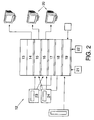
- the devices forming part of the post-processing stage (12) are shown in figure 2 , containing a diagrammatic representation of these devices, which act together with the specific algorithms developed to automate and optimize the tasks performed during analysis in the laboratory and which basically consist of a post- processing PC (13) that comprises a whole series of devices required for the processing of the images, such as a detailed image capturing card(14), a video image digitalization card (15), an infrared image digitalization card(16), two communications ports (17 and 18), SCSI controller card (19), as well as the respective display monitors (20), DVD (21), CD - ROM (22) and video units (23 y 24).
- a post- processing PC (13) that comprises a whole series of devices required for the processing of the images, such as a detailed image capturing card(14), a video image digitalization card (15), an infrared image digitalization card(16), two communications ports (17 and 18), SCSI controller card (19), as well as the respective display monitors (20), DVD (21), CD - ROM (22) and video units
- the efficiency of the first inspection that is performed on a facility may fall short of the objective defined. In this case the data obtained from the first inspection would be fed back into the system, so that the efficiency of the inspection is increased at later inspections.
Landscapes
- Image Processing (AREA)
- Investigating Materials By The Use Of Optical Means Adapted For Particular Applications (AREA)
- Closed-Circuit Television Systems (AREA)
- Control Of Vehicles With Linear Motors And Vehicles That Are Magnetically Levitated (AREA)
- Investigating Or Analyzing Materials By The Use Of Ultrasonic Waves (AREA)
- Vehicle Body Suspensions (AREA)
- Electric Cable Installation (AREA)
Claims (14)
- Vorrichtung zur Untersuchung linearer Infrastrukturen, bestehend aus einem in einem Fahrzeug installierten System (11) zur automatischen Erfassung und Aufnahme von Bildern und Daten, und einer nicht an Bord des Fahrzeugs befindlichen Nachverarbeitungseinheit (12), welche das Verarbeiten von durch das Bordsystem (11) erhaltenen Informationen und/oder Signalen ermöglicht, dadurch gekennzeichnet, dass das Erfassen und Aufnehmen von Bildern und Daten durch Bordeinrichtungen ungeachtet der Bewegung des Fahrzeugs und unter verschiedenen Winkeln und Sichtlinien gleichzeitig durchgeführt wird, wobei die Einrichtung in automatischer oder halbautomatischer Weise auf der Basis von in dem System gespeicherten Daten auf die lineare Infrastruktur gerichtet wird, wobei die Daten die Raumpositionen der zu untersuchenden Einrichtungen betreffen.
- Vorrichtung zum Untersuchen linearer Infrastrukturen nach Anspruch 1, dadurch gekennzeichnet, dass das Bordsystem (11) zwei kreiselstabilisierte Plattformen (1, 2) aufweist, welche unabhängig voneinander gleichzeitig und ungeachtet der Bewegung des Fahrzeugs arbeiten, wobei die Plattformen (1, 2) die Einrichtungen zum Erfassen und Aufnehmen von Bildern aufweisen.
- Vorrichtung zum Untersuchen linearer Infrastrukturen nach Anspruch 2, dadurch gekennzeichnet, dass eine der kreiselstabilisierten Plattformen (1) entweder automatisch oder manuell gelenkt oder gerichtet wird und Einrichtungen zum Erfassen und Aufnehmen von Videoformat-Daten der Leitungsumgebung und ferner einen Infrarotsensor aufweist, welcher Infrarotbilder und Thermogramme liefert.
- Vorrichtung zum Untersuchen linearer Infrastrukturen nach Anspruch 2, dadurch gekennzeichnet, dass die andere kreiselstabilisierte Plattform (2) automatisch gelenkt oder gerichtet wird und aus einem digitalen Videosystem besteht, das hochaufgelöste Digitalfotografien aufnimmt.
- Vorrichtung nach einem der vorhergehenden Ansprüche, dadurch gekennzeichnet, dass die Bilderfassungseinrichtungen gleichzeitig Videoformat-Bilder der Infrastruktur in ihrer Umgebung, Infrarotbilder und Thermogramme sowie hochaufgelöste Digitalfotografien mit detaillierten Informationen über den Zustand der Einrichtungen der linearen Infrastruktur liefern.
- Vorrichtung nach einem der vorhergehenden Ansprüche, dadurch gekennzeichnet, dass sie Einrichtungen aufweist, welche die in Echtzeit durch das System gespeicherten und erfassten Daten zum Berechnen und Steuern der Sichtlinien der die Vorrichtung bildenden Systeme zur Daten- und/oder Bilderfassung verwenden.
- Vorrichtung zum Untersuchen linearer Infrastrukturen nach Anspruch 6, dadurch gekennzeichnet, dass die Sichtlinien und die Sichtfeder der Bild- und Datenerfassungsvorrichtungen voneinander unabhängig und parametrierbare Eigenschaften der zu untersuchenden Infrastruktur sind.
- Vorrichtung zum Untersuchen linearer Infrastrukturen nach Anspruch 1, dadurch gekennzeichnet, dass das Bordsystem (11) ferner Einrichtungen zur Echtzeiterfassung von Daten bezüglich der Lage sowie der geographischen Position aufweist.
- Vorrichtung nach einem der vorhergehenden Ansprüche, dadurch gekennzeichnet, dass das Bordsystem (11) ferner Einrichtungen zum Aufzeichnen und Speichern der erfassten und aufgenommenen Informationen mit einer gemeinsamen Zeitbasis aufweist, so dass bei der nachfolgenden Verarbeitung im Labor die gesamte Untersuchung in synchronisierter Form reproduziert werden kann, mit dem Ergebnis, dass über einen einzelnen Eingang direkter Zugriff auf jede beliebige der Datenquellen erhältlich ist.
- Vorrichtung zum Untersuchen linearer Infrastrukturen nach Anspruch 1, dadurch gekennzeichnet, dass die Nachverarbeitungseinheit (12) Einrichtungen aufweist, welche zur Berechnung der geographischen Position der bei der Untersuchung erkannten Defekte sowie der Position der Infrastruktur selbst mittels Triangulationsalgorithmen geeignet sind, die zum Berechnen der globalen 3D-Position eines Objekts anhand von zwei aus verschiedenen Winkeln aufgenommenen Bildern entwickelt wurden, und ferner dadurch gekennzeichnet, dass die Nachverarbeitungsstufe (12) Einrichtungen zur automatischen Hotspot-Erkennung anhand der von dem Bordsystem (11) erfassten Infrarotspektrumbilder aufweist.
- Vorrichtung zum Untersuchen linearer Infrastrukturen nach einem der Ansprüche 1- 10, dadurch gekennzeichnet, dass das Fahrzeug, in welchem das Bordsystem (11) installiert ist, ein Flugzeug oder ein Landfahrzeug ist.
- Verfahren zum Untersuchen linearer Infrastrukturen, mit den folgenden Schritten:- Verwenden gespeicherter Daten bezüglich der räumlichen Position der zu untersuchenden Infrastruktur,- automatisches panoramisches visuelles Erfassen der zu untersuchenden linearen Infrastruktur und deren Umgebung in Videoformat,- automatisches detailliertes visuelles Erfassen der Elemente der zu untersuchenden linearen Infrastruktur mittels digitaler Abbildungen der Elemente der genannten Infrastruktur,- automatisches Erfassen der Elemente der untersuchten Infrastruktur im Infrarotspektrum und Erkennung möglicher Hotspots in der Einrichtung anhand dieser Bildern bei der Nachverarbeitung,- Aufzeichnen der von den Sensoren, Filmkameras, Navigations- und Steuerungs- und Audiosensoren, welche Teil der Vorrichtung sind, erfassten Daten durch das Bordsystem (11) mit einer gemeinsamen Zeitbasis,- Verwenden einer nicht an Bord des Fahrzeugs installierten Nachverarbeitungseinheit (12), welche die von der in dem Fahrzeug installierten Einheit bei der Untersuchung der linearen Infrastruktur erfassten Daten und Bilder verwaltet und analysiert,- Speichern der von der Nachverarbeitungseinheit (12) verarbeiteten Daten,- Erzeugen von Berichten über den Zustand, die Situation und Defekte, welche in der analysierten linearen Infrastruktur vorgefunden wurden.
- Verfahren zum Untersuchen linearer Infrastrukturen, mit den folgenden Schritten:- panoramisches visuelles Erfassen der zu untersuchenden linearen Infrastruktur und deren Umgebung durch manuelle Bedienung mit Bedienerintervention und in Videoformat,- automatisches detailliertes visuelles Erfassen der Elemente der zu untersuchenden linearen Infrastruktur mittels digitaler Abbildungen der Elemente der genannten Infrastruktur,- automatisches Erfassen der Elemente der untersuchten Infrastruktur im Infrarotspektrum und Erkennung möglicher Hotspots in der Einrichtung anhand dieser Bildern bei der Nachverarbeitung,- Aufzeichnen der von den Sensoren, Filmkameras, Navigations- und Steuerungs- und Audiosensoren, welche Teil der Vorrichtung sind, erfassten Daten durch das Bordsystem (11) mit einer gemeinsamen Zeitbasis,- Verwenden einer nicht an Bord des Fahrzeugs installierten Nachverarbeitungseinheit (12), welche die von der in dem Fahrzeug installierten Einheit bei der Untersuchung der linearen Infrastruktur erfassten Daten und Bilder verwaltet und analysiert,- Speichern der von der Nachverarbeitungseinheit (12) verarbeiteten Daten,- Erzeugen von Berichten über den Zustand, die Situation und Defekte, welche in der analysierten linearen Infrastruktur vorgefunden wurden.
- Verfahren zum Untersuchen linearer Infrastrukturen nach den Ansprüchen 12 oder 13, dadurch gekennzeichnet, dass durch die Nachverarbeitungseinheit (12) erhaltene und verarbeitete Positionsdaten der linearen Infrastruktur die erforderliche Genauigkeit aufweisen, um das System bei nachfolgenden Untersuchungen linearer Infrastrukturen zu versorgen.
Applications Claiming Priority (1)
| Application Number | Priority Date | Filing Date | Title |
|---|---|---|---|
| PCT/ES2002/000389 WO2004015833A1 (es) | 2002-08-01 | 2002-08-01 | Método y dispositivo para la inspección de infraestructuras lineales |
Publications (2)
| Publication Number | Publication Date |
|---|---|
| EP1548908A1 EP1548908A1 (de) | 2005-06-29 |
| EP1548908B1 true EP1548908B1 (de) | 2010-01-13 |
Family
ID=31502884
Family Applications (1)
| Application Number | Title | Priority Date | Filing Date |
|---|---|---|---|
| EP02755016A Expired - Lifetime EP1548908B1 (de) | 2002-08-01 | 2002-08-01 | Verfahren und einrichtung zur untersuchung linearer infrastrukturen |
Country Status (9)
| Country | Link |
|---|---|
| US (1) | US20050238220A1 (de) |
| EP (1) | EP1548908B1 (de) |
| AT (1) | ATE455383T1 (de) |
| AU (1) | AU2002321319A1 (de) |
| BR (1) | BR0215828A (de) |
| DE (1) | DE60235124D1 (de) |
| ES (1) | ES2353189T3 (de) |
| MX (1) | MXPA05001278A (de) |
| WO (1) | WO2004015833A1 (de) |
Families Citing this family (8)
| Publication number | Priority date | Publication date | Assignee | Title |
|---|---|---|---|---|
| ATE409329T1 (de) * | 2003-07-24 | 2008-10-15 | Harman Becker Automotive Sys | Verfahren zur bereitstellung von daten in einer mobile vorrichtung und system |
| JP2008276805A (ja) * | 2008-08-04 | 2008-11-13 | Central Res Inst Of Electric Power Ind | 電線点検用画像の作成方法 |
| US8577518B2 (en) * | 2009-05-27 | 2013-11-05 | American Aerospace Advisors, Inc. | Airborne right of way autonomous imager |
| CN103812052B (zh) * | 2014-03-07 | 2016-06-01 | 国家电网公司 | 一种用于无人机输电线路巡检的集中监控系统及监控方法 |
| CN105334862A (zh) * | 2015-10-28 | 2016-02-17 | 上海同筑信息科技有限公司 | 基于bim的无人机监控方法及系统 |
| ES3061750T3 (en) | 2017-03-15 | 2026-04-07 | Siemens Energy Global Gmbh & Co Kg | Method and assembly for monitoring the state of a system with operating elements |
| ES2893998A1 (es) | 2020-07-31 | 2022-02-10 | Arborea Intellbird Sl | Sistema y procedimiento de inspeccion de infraestructuras |
| CN113596412B (zh) * | 2021-09-29 | 2022-01-25 | 北京思汇达电力科技有限公司 | 一种电力线路监拍终端系统和方法 |
Family Cites Families (12)
| Publication number | Priority date | Publication date | Assignee | Title |
|---|---|---|---|---|
| JPH0236707A (ja) * | 1988-07-26 | 1990-02-06 | Fujikura Ltd | 架空電線路の点検方法 |
| JP2661975B2 (ja) * | 1988-08-04 | 1997-10-08 | 古河電気工業株式会社 | 架空送電線路の点検方法および装置 |
| JPH0274111A (ja) * | 1988-09-09 | 1990-03-14 | Fujikura Ltd | 架空線路の点検装置 |
| JPH06103967B2 (ja) * | 1989-07-26 | 1994-12-14 | 三菱電機株式会社 | 架空線点検用画像処理装置 |
| JPH0360313A (ja) * | 1989-07-26 | 1991-03-15 | Mitsubishi Electric Corp | 架空線点検用画像処理装置 |
| JPH06103968B2 (ja) * | 1989-07-26 | 1994-12-14 | 三菱電機株式会社 | 架空線点検用画像処理装置 |
| US5045937A (en) * | 1989-08-25 | 1991-09-03 | Space Island Products & Services, Inc. | Geographical surveying using multiple cameras to obtain split-screen images with overlaid geographical coordinates |
| JP2769036B2 (ja) * | 1990-10-17 | 1998-06-25 | 中部電力株式会社 | 架空線の自動点検方法 |
| JPH04252982A (ja) * | 1991-01-30 | 1992-09-08 | Nec Corp | 精測レーダ飛行点検方式 |
| JP3419636B2 (ja) * | 1996-10-09 | 2003-06-23 | 三菱電機株式会社 | 架空線の自動点検装置 |
| WO2005017550A2 (en) * | 2002-12-13 | 2005-02-24 | Utah State University Research Foundation | A vehicle mounted system and method for capturing and processing physical data |
| GB0311138D0 (en) * | 2003-05-15 | 2003-06-18 | Univ Wales Bangor | Improvements in or relating to diagnostics |
-
2002
- 2002-08-01 DE DE60235124T patent/DE60235124D1/de not_active Expired - Lifetime
- 2002-08-01 EP EP02755016A patent/EP1548908B1/de not_active Expired - Lifetime
- 2002-08-01 MX MXPA05001278A patent/MXPA05001278A/es active IP Right Grant
- 2002-08-01 BR BR0215828-0A patent/BR0215828A/pt not_active IP Right Cessation
- 2002-08-01 AT AT02755016T patent/ATE455383T1/de not_active IP Right Cessation
- 2002-08-01 AU AU2002321319A patent/AU2002321319A1/en not_active Abandoned
- 2002-08-01 WO PCT/ES2002/000389 patent/WO2004015833A1/es not_active Ceased
- 2002-08-01 ES ES02755016T patent/ES2353189T3/es not_active Expired - Lifetime
-
2005
- 2005-01-31 US US11/048,299 patent/US20050238220A1/en not_active Abandoned
Also Published As
| Publication number | Publication date |
|---|---|
| WO2004015833A1 (es) | 2004-02-19 |
| AU2002321319A1 (en) | 2004-02-25 |
| BR0215828A (pt) | 2005-07-05 |
| MXPA05001278A (es) | 2005-10-06 |
| US20050238220A1 (en) | 2005-10-27 |
| EP1548908A1 (de) | 2005-06-29 |
| ATE455383T1 (de) | 2010-01-15 |
| ES2353189T3 (es) | 2011-02-28 |
| DE60235124D1 (de) | 2010-03-04 |
Similar Documents
| Publication | Publication Date | Title |
|---|---|---|
| JP4475632B2 (ja) | 無人飛行体を用いた送電線点検システム | |
| JP7030431B2 (ja) | 点検支援システム及び点検支援制御プログラム | |
| US11017228B2 (en) | Method and arrangement for condition monitoring of an installation with operating means | |
| JP6826421B2 (ja) | 設備巡視システム及び設備巡視方法 | |
| CN112327906A (zh) | 一种基于无人机的智能自动巡检系统 | |
| US20200034637A1 (en) | Real-Time Track Asset Recognition and Position Determination | |
| CN115219451A (zh) | 一种机载激光甲烷探测巡检的装置、方法及系统 | |
| CN102436738A (zh) | 一种基于无人机的交通监测装置 | |
| US20090245581A1 (en) | Airborne terrain acquisition and processing system with fluid detection | |
| EP1548908A1 (de) | Verfahren und einrichtung zur untersuchung linearer infrastrukturen | |
| CN113537526A (zh) | 一种基于bim的公路工程巡检处理方法和系统 | |
| US20210176434A1 (en) | Method and assembly for detecting corona discharges of a system comprising equipment | |
| KR102688780B1 (ko) | 무인항공기를 이용한 송전설비의 진단방법 | |
| CN104519314A (zh) | 事故现场全景信息快速采集方法 | |
| US20220178689A1 (en) | Camera triggering and multi-camera photogrammetry | |
| RU2699940C1 (ru) | Способ мониторинга состояния трассы магистрального трубопровода | |
| CN114078084A (zh) | 一种基于坐标映射实现目标定位及跟踪的方法 | |
| Jasiobedzki et al. | C2SM: a mobile system for detecting and 3D mapping of chemical, radiological, and nuclear contamination | |
| Kunz et al. | Multi sensor and smart gimbal for enhanced powerline monitoring on helicopter and UAVs | |
| CN116012611A (zh) | 路产检测方法及载具 | |
| JP2023112536A (ja) | 路面損傷位置の算定方法 | |
| CN116227849B (zh) | 一种用于企业危险作业的规范化管理及预警系统 | |
| CN113640830A (zh) | 一种无人机桥底检测系统 | |
| RU2780304C1 (ru) | Способ мониторинга технического состояния объектов транспорта газа на основе геоинформационной системы | |
| KR102827712B1 (ko) | 비행체 자동추적 기능이 구비된 영상 계측 방법 및 장치 |
Legal Events
| Date | Code | Title | Description |
|---|---|---|---|
| PUAI | Public reference made under article 153(3) epc to a published international application that has entered the european phase |
Free format text: ORIGINAL CODE: 0009012 |
|
| 17P | Request for examination filed |
Effective date: 20050217 |
|
| AK | Designated contracting states |
Kind code of ref document: A1 Designated state(s): AT BE BG CH CY CZ DE DK EE ES FI FR GB GR IE IT LI LU MC NL PT SE SK TR |
|
| AX | Request for extension of the european patent |
Extension state: AL LT LV MK RO SI |
|
| DAX | Request for extension of the european patent (deleted) | ||
| 17Q | First examination report despatched |
Effective date: 20081120 |
|
| GRAP | Despatch of communication of intention to grant a patent |
Free format text: ORIGINAL CODE: EPIDOSNIGR1 |
|
| GRAS | Grant fee paid |
Free format text: ORIGINAL CODE: EPIDOSNIGR3 |
|
| GRAA | (expected) grant |
Free format text: ORIGINAL CODE: 0009210 |
|
| AK | Designated contracting states |
Kind code of ref document: B1 Designated state(s): AT BE BG CH CY CZ DE DK EE ES FI FR GB GR IE IT LI LU MC NL PT SE SK TR |
|
| REG | Reference to a national code |
Ref country code: GB Ref legal event code: FG4D |
|
| REG | Reference to a national code |
Ref country code: CH Ref legal event code: EP |
|
| REG | Reference to a national code |
Ref country code: IE Ref legal event code: FG4D |
|
| REF | Corresponds to: |
Ref document number: 60235124 Country of ref document: DE Date of ref document: 20100304 Kind code of ref document: P |
|
| REG | Reference to a national code |
Ref country code: NL Ref legal event code: VDEP Effective date: 20100113 |
|
| PG25 | Lapsed in a contracting state [announced via postgrant information from national office to epo] |
Ref country code: AT Free format text: LAPSE BECAUSE OF FAILURE TO SUBMIT A TRANSLATION OF THE DESCRIPTION OR TO PAY THE FEE WITHIN THE PRESCRIBED TIME-LIMIT Effective date: 20100113 |
|
| PG25 | Lapsed in a contracting state [announced via postgrant information from national office to epo] |
Ref country code: NL Free format text: LAPSE BECAUSE OF FAILURE TO SUBMIT A TRANSLATION OF THE DESCRIPTION OR TO PAY THE FEE WITHIN THE PRESCRIBED TIME-LIMIT Effective date: 20100113 Ref country code: PT Free format text: LAPSE BECAUSE OF FAILURE TO SUBMIT A TRANSLATION OF THE DESCRIPTION OR TO PAY THE FEE WITHIN THE PRESCRIBED TIME-LIMIT Effective date: 20100513 |
|
| PG25 | Lapsed in a contracting state [announced via postgrant information from national office to epo] |
Ref country code: FI Free format text: LAPSE BECAUSE OF FAILURE TO SUBMIT A TRANSLATION OF THE DESCRIPTION OR TO PAY THE FEE WITHIN THE PRESCRIBED TIME-LIMIT Effective date: 20100113 |
|
| PG25 | Lapsed in a contracting state [announced via postgrant information from national office to epo] |
Ref country code: CY Free format text: LAPSE BECAUSE OF FAILURE TO SUBMIT A TRANSLATION OF THE DESCRIPTION OR TO PAY THE FEE WITHIN THE PRESCRIBED TIME-LIMIT Effective date: 20100113 Ref country code: BE Free format text: LAPSE BECAUSE OF FAILURE TO SUBMIT A TRANSLATION OF THE DESCRIPTION OR TO PAY THE FEE WITHIN THE PRESCRIBED TIME-LIMIT Effective date: 20100113 Ref country code: EE Free format text: LAPSE BECAUSE OF FAILURE TO SUBMIT A TRANSLATION OF THE DESCRIPTION OR TO PAY THE FEE WITHIN THE PRESCRIBED TIME-LIMIT Effective date: 20100113 Ref country code: GR Free format text: LAPSE BECAUSE OF FAILURE TO SUBMIT A TRANSLATION OF THE DESCRIPTION OR TO PAY THE FEE WITHIN THE PRESCRIBED TIME-LIMIT Effective date: 20100414 Ref country code: SE Free format text: LAPSE BECAUSE OF FAILURE TO SUBMIT A TRANSLATION OF THE DESCRIPTION OR TO PAY THE FEE WITHIN THE PRESCRIBED TIME-LIMIT Effective date: 20100113 |
|
| PLBE | No opposition filed within time limit |
Free format text: ORIGINAL CODE: 0009261 |
|
| STAA | Information on the status of an ep patent application or granted ep patent |
Free format text: STATUS: NO OPPOSITION FILED WITHIN TIME LIMIT |
|
| PG25 | Lapsed in a contracting state [announced via postgrant information from national office to epo] |
Ref country code: SK Free format text: LAPSE BECAUSE OF FAILURE TO SUBMIT A TRANSLATION OF THE DESCRIPTION OR TO PAY THE FEE WITHIN THE PRESCRIBED TIME-LIMIT Effective date: 20100113 Ref country code: BG Free format text: LAPSE BECAUSE OF FAILURE TO SUBMIT A TRANSLATION OF THE DESCRIPTION OR TO PAY THE FEE WITHIN THE PRESCRIBED TIME-LIMIT Effective date: 20100413 Ref country code: CZ Free format text: LAPSE BECAUSE OF FAILURE TO SUBMIT A TRANSLATION OF THE DESCRIPTION OR TO PAY THE FEE WITHIN THE PRESCRIBED TIME-LIMIT Effective date: 20100113 |
|
| 26N | No opposition filed |
Effective date: 20101014 |
|
| PG25 | Lapsed in a contracting state [announced via postgrant information from national office to epo] |
Ref country code: DK Free format text: LAPSE BECAUSE OF FAILURE TO SUBMIT A TRANSLATION OF THE DESCRIPTION OR TO PAY THE FEE WITHIN THE PRESCRIBED TIME-LIMIT Effective date: 20100113 |
|
| REG | Reference to a national code |
Ref country code: ES Ref legal event code: FG2A Effective date: 20110216 |
|
| PG25 | Lapsed in a contracting state [announced via postgrant information from national office to epo] |
Ref country code: MC Free format text: LAPSE BECAUSE OF NON-PAYMENT OF DUE FEES Effective date: 20100831 |
|
| REG | Reference to a national code |
Ref country code: CH Ref legal event code: PL |
|
| GBPC | Gb: european patent ceased through non-payment of renewal fee |
Effective date: 20100801 |
|
| PG25 | Lapsed in a contracting state [announced via postgrant information from national office to epo] |
Ref country code: LI Free format text: LAPSE BECAUSE OF NON-PAYMENT OF DUE FEES Effective date: 20100831 Ref country code: CH Free format text: LAPSE BECAUSE OF NON-PAYMENT OF DUE FEES Effective date: 20100831 |
|
| REG | Reference to a national code |
Ref country code: FR Ref legal event code: ST Effective date: 20110502 |
|
| PG25 | Lapsed in a contracting state [announced via postgrant information from national office to epo] |
Ref country code: IT Free format text: LAPSE BECAUSE OF NON-PAYMENT OF DUE FEES Effective date: 20100801 |
|
| REG | Reference to a national code |
Ref country code: DE Ref legal event code: R119 Ref document number: 60235124 Country of ref document: DE Effective date: 20110301 |
|
| PG25 | Lapsed in a contracting state [announced via postgrant information from national office to epo] |
Ref country code: DE Free format text: LAPSE BECAUSE OF NON-PAYMENT OF DUE FEES Effective date: 20110301 Ref country code: IE Free format text: LAPSE BECAUSE OF NON-PAYMENT OF DUE FEES Effective date: 20100801 Ref country code: FR Free format text: LAPSE BECAUSE OF NON-PAYMENT OF DUE FEES Effective date: 20100831 |
|
| PG25 | Lapsed in a contracting state [announced via postgrant information from national office to epo] |
Ref country code: GB Free format text: LAPSE BECAUSE OF NON-PAYMENT OF DUE FEES Effective date: 20100801 |
|
| REG | Reference to a national code |
Ref country code: ES Ref legal event code: FD2A Effective date: 20111019 |
|
| PG25 | Lapsed in a contracting state [announced via postgrant information from national office to epo] |
Ref country code: ES Free format text: LAPSE BECAUSE OF NON-PAYMENT OF DUE FEES Effective date: 20100802 |
|
| PG25 | Lapsed in a contracting state [announced via postgrant information from national office to epo] |
Ref country code: LU Free format text: LAPSE BECAUSE OF NON-PAYMENT OF DUE FEES Effective date: 20100801 |
|
| PG25 | Lapsed in a contracting state [announced via postgrant information from national office to epo] |
Ref country code: TR Free format text: LAPSE BECAUSE OF FAILURE TO SUBMIT A TRANSLATION OF THE DESCRIPTION OR TO PAY THE FEE WITHIN THE PRESCRIBED TIME-LIMIT Effective date: 20100113 |