EP1548871A1 - Bordseitiger Signalgeber zur Durchführung schlüssellosen Zuganges - Google Patents
Bordseitiger Signalgeber zur Durchführung schlüssellosen Zuganges Download PDFInfo
- Publication number
- EP1548871A1 EP1548871A1 EP04291697A EP04291697A EP1548871A1 EP 1548871 A1 EP1548871 A1 EP 1548871A1 EP 04291697 A EP04291697 A EP 04291697A EP 04291697 A EP04291697 A EP 04291697A EP 1548871 A1 EP1548871 A1 EP 1548871A1
- Authority
- EP
- European Patent Office
- Prior art keywords
- vehicle
- wire conductors
- loop
- wire
- output terminals
- Prior art date
- Legal status (The legal status is an assumption and is not a legal conclusion. Google has not performed a legal analysis and makes no representation as to the accuracy of the status listed.)
- Granted
Links
- 238000000034 method Methods 0.000 title claims abstract description 9
- 239000004020 conductor Substances 0.000 claims abstract description 95
- 239000003990 capacitor Substances 0.000 claims description 7
- 238000004804 winding Methods 0.000 claims description 4
- 230000005284 excitation Effects 0.000 claims description 3
- 230000005540 biological transmission Effects 0.000 description 28
- 230000005855 radiation Effects 0.000 description 9
- 238000004891 communication Methods 0.000 description 8
- 238000001514 detection method Methods 0.000 description 7
- 230000008901 benefit Effects 0.000 description 5
- 238000005259 measurement Methods 0.000 description 5
- 238000009434 installation Methods 0.000 description 2
- 230000008054 signal transmission Effects 0.000 description 2
- 229910000859 α-Fe Inorganic materials 0.000 description 2
- 230000003213 activating effect Effects 0.000 description 1
- 230000007423 decrease Effects 0.000 description 1
- 230000004807 localization Effects 0.000 description 1
- 239000000463 material Substances 0.000 description 1
- 239000002184 metal Substances 0.000 description 1
- 238000012986 modification Methods 0.000 description 1
- 230000004048 modification Effects 0.000 description 1
- 238000012544 monitoring process Methods 0.000 description 1
- 238000012545 processing Methods 0.000 description 1
- 230000001960 triggered effect Effects 0.000 description 1
Images

Classifications
-
- H—ELECTRICITY
- H01—ELECTRIC ELEMENTS
- H01Q—ANTENNAS, i.e. RADIO AERIALS
- H01Q3/00—Arrangements for changing or varying the orientation or the shape of the directional pattern of the waves radiated from an antenna or antenna system
- H01Q3/24—Arrangements for changing or varying the orientation or the shape of the directional pattern of the waves radiated from an antenna or antenna system varying the orientation by switching energy from one active radiating element to another, e.g. for beam switching
-
- H—ELECTRICITY
- H01—ELECTRIC ELEMENTS
- H01Q—ANTENNAS, i.e. RADIO AERIALS
- H01Q1/00—Details of, or arrangements associated with, antennas
- H01Q1/27—Adaptation for use in or on movable bodies
- H01Q1/32—Adaptation for use in or on road or rail vehicles
- H01Q1/3208—Adaptation for use in or on road or rail vehicles characterised by the application wherein the antenna is used
- H01Q1/3233—Adaptation for use in or on road or rail vehicles characterised by the application wherein the antenna is used particular used as part of a sensor or in a security system, e.g. for automotive radar, navigation systems
- H01Q1/3241—Adaptation for use in or on road or rail vehicles characterised by the application wherein the antenna is used particular used as part of a sensor or in a security system, e.g. for automotive radar, navigation systems particular used in keyless entry systems
-
- H—ELECTRICITY
- H01—ELECTRIC ELEMENTS
- H01Q—ANTENNAS, i.e. RADIO AERIALS
- H01Q1/00—Details of, or arrangements associated with, antennas
- H01Q1/27—Adaptation for use in or on movable bodies
- H01Q1/32—Adaptation for use in or on road or rail vehicles
- H01Q1/325—Adaptation for use in or on road or rail vehicles characterised by the location of the antenna on the vehicle
- H01Q1/3291—Adaptation for use in or on road or rail vehicles characterised by the location of the antenna on the vehicle mounted in or on other locations inside the vehicle or vehicle body
-
- H—ELECTRICITY
- H01—ELECTRIC ELEMENTS
- H01Q—ANTENNAS, i.e. RADIO AERIALS
- H01Q7/00—Loop antennas with a substantially uniform current distribution around the loop and having a directional radiation pattern in a plane perpendicular to the plane of the loop
Definitions
- the present invention relates to an on-board signal transmitter for a motor vehicle, capable of communicating with a portable receiver for implementing a keyless entry and/or keyless ignition procedure.
- a typical configuration for keyless car systems is the use of a two way radio communication between the vehicle and an electronic key.
- the position of the electronic key has to be monitored while the communication occurs.
- a low frequency communication e.g. 20 kHz, 125 kHz, 13,56MHz.
- a higher frequency is recommended (e.g. 315MHz, 433MHz, 868MHz, 2,45GHz) in order to benefit from a higher data rate and to save communication time, i.e. extend the battery life.
- the state of the art system includes the use of ferrite core coil antennas placed in door handles or inside the doors. Each antenna has to be tuned and separately wired to the central unit. This is labour-intensive and costly, because a fully protected keyless system would require up to ten ferrite antennas.
- FR2839785 discloses a vehicle comprising an on-board signal transmitter capable of communicating with a portable receiver for implementing a keyless entry and/or keyless ignition procedure.
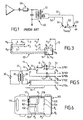
- Fig. 1 shows the signal transmission system 50 of this prior art vehicle. It includes a pair of output wires 51 and 52 which are electrically connected to a pair of corresponding connection points 53 and 54 on the vehicle body 55.
- An antenna driver circuit 56 with a current transformer 57 generates an electrical current in the output wires 51 and 52 so as to radiate a magnetic field which can serve to communicate with an electronic key. Due to the conductivity of the metal, an electrical current I body is caused to flow through the vehicle body 55 from one connection point to the other as shown in Fig.1.
- This prior art discloses also a loop antenna made of wire which extends around the passenger compartment of a car.
- the radiated magnetic field is not homogeneous throughout the passenger compartment and decreases rapidly in the middle of the loop.
- An object of the invention is to provide an on-board transmitter device with transmission antennas, which makes it possible to obtain a precise localisation of an electronic key while reducing the material and installation cost of the device.
- Another object of the invention is to provide simple and cost-effective antenna systems, making it possible to attain a consistent coverage of the vehicle's interior space.
- the invention provides a vehicle comprising an on-board signal transmitter capable of communicating with a portable receiver for implementing a keyless entry and/or keyless ignition procedure, said signal transmitter including a plurality of output terminals which are electrically connected to a plurality of corresponding connection points on the vehicle body through wire conductors, said signal transmitter including electrical driving means for electrically exciting a pair of said output terminals so as to generate an electrical current in the corresponding pair of wire conductors, characterized in that the signal transmitter includes output selection means operable in at least two respective states for selectively outputting said electrical excitation to at least two respective pairs of said output terminals, the output terminals being at least three in number, wherein for at least one of said pairs of output terminals, the corresponding pair of connection points on the vehicle body and two wire conductors connecting the said output terminals to the said connection points are arranged in such a manner that a portion of the vehicle body which extends between both connection points and the two wire conductors connected thereto form a loop which surrounds at least a portion of
- Two wire conductors each connecting an output terminal of the transmitter to a connection point on the vehicle body, form a transmission antenna which is capable of radiating a magnetic field.
- a portion of the vehicle body which extends between both connection points and the two wire conductors connected thereto constitute a circuit through which an electrical current can flow from one of the output terminals to the other.
- Such a configuration i.e. a hybrid loop made of both wire conductor and body bulk, radiates a magnetic field similar to that of a loop antenna made of wire.
- the vehicle body makes only a small contribution to the magnetic radiation of the antenna.
- the field strength of this transmission antenna architecture depends on the distance between the connection points, the area between both wire conductors, the length of the both wire conductors, the shape of the area between both wire conductors and the electrical current in the hybrid loop made of both wire conductors and body bulk.
- the output selection means makes it possible to output an electrical excitation to a high number of such transmission antennas, hence to transmit a signal in a high number of specific transmission areas inside and/or outside the vehicle, so that a precise detection of the receiver position, i.e. the position of the electronic key, can be obtained.
- At least one of the output terminals belongs to at least two of the said pairs of output terminals, which are electrically excitable in at least two different states of the output selection means.
- a high number of transmission areas can be formed with a reduced number of output terminals on the transmitter side and less antenna wiring is required because any output terminals and the wire conductor connected thereto can operate with a number of other output terminals to constitute a number of different transmission antennas with different coverage.
- the two wire conductors are twisted together along a portion of their length, which extends substantially from the signal transmitter up to a branching point where the two wire conductors separate from one another.
- This feature makes it possible to arrange a hybrid loop at any position regardless of the position of the transmitter by covering the distance between the transmitter output and the hybrid loop with wire conductors that are twisted together. Intertwined wire conductors do not contribute substantially to the magnetic radiation of the antenna. Hence, such a configuration is substantially equivalent to a magnetic loop which closes at the branching point.
- the electrical driving means includes a driver circuit and the output selection means includes a switching device operable in at least two respective states for selectively connecting said driver circuit to at least two respective pairs of said output terminals.
- the output selection means includes a switching device operable in at least two respective states for selectively connecting said driver circuit to at least two respective pairs of said output terminals.
- a single driver circuit is rendered connectable to all the respective pairs of output terminals.
- the hybrid loop made of both wire conductor and body bulk includes a tuning capacitor.
- the electrical driving means includes an electrical transformer with a secondary winding which is connected or connectable to at least one of said pairs of output terminals.
- the invention provides also a vehicle comprising an on-board signal transmitter capable of communicating with a portable receiver for implementing a keyless entry and/or keyless ignition procedure, said signal transmitter having a loop antenna made of conductive material and arranged around at least a portion of the vehicle interior space, as seen in projection, for radiating a magnetic field, said loop antenna being connected to the signal transmitter by two wire conductors which extend from the signal transmitter, characterized in that the two wire conductors are twisted together along a portion of their length down to a branching point where the two wire conductors separate from one another in order to form at least a portion of said loop antenna.
- This feature makes it possible to arrange a loop antenna at any position independently of the position of the transmitter by covering the distance between the transmitter output and the loop antenna with wire conductors that are twisted together. Intertwined wire conductors do not contribute substantially to the magnetic radiation of the antenna. Hence, such a configuration is substantially equivalent to a magnetic loop which closes at the branching point. Since the intertwined portion of the pair of wire conductors does not affect the radiation pattern of the loop antenna, the antenna can be placed at all appropriate locations with respect to the transmission areas to be covered, regardless of the location of the transmitter in the vehicle. Hence, the antenna system is very flexible and can be easily adapted to all types of vehicles.
- each said wire conductor is connected to a respective connection point on the vehicle body, said loop antenna consisting of the two wire conductors and a portion of the vehicle body which extends between both connection points.
- Two wire conductors each connecting an output terminal of the transmitter to a connection point on the vehicle body, form a transmission antenna which is capable of radiating a magnetic field.
- a portion of the vehicle body which extends between both connection points and the two wire conductors connected thereto constitute a circuit through which an electrical current can flow from one of the output terminals to the other.
- Such a configuration i.e. a hybrid loop made of both wire conductor and body bulk, radiates a magnetic field similar to that of a loop antenna made of wire.
- the vehicle body makes only a small contribution to the magnetic radiation of the antenna.
- the field strength of this transmission antenna architecture depends on the distance between the connection points, the area between both wire conductors, the length of the both wire conductors, the shape of the area between both wire conductors and the electrical current in the hybrid loop made of both wire conductors and body bulk.
- a capacitor is arranged between a conductor and the corresponding connection point on the vehicle body.
- said loop antenna is entirely constituted by said wire conductors.
- the two wire conductors are two portions of a single wire in an uninterrupted circuit which is arranged in the form of a whole loop.
- a portion of the two wire conductors located between said intertwined portion and said transmitter form a second loop antenna arranged around at least a portion of the vehicle interior space, as seen in projection, wherein said intertwined portion connects both loop antennas in series.
- the two wire conductors include a further intertwined portion which extends from said second loop antenna to said transmitter.
- both loop antennas and both intertwined pairs are made of a single wire in an uninterrupted circuit, wherein the two wire conductors are two portions of said single wire.
- At least one loop is formed around the luggage compartment of the vehicle as seen in vertical projection, and/or around a centre portion of the passenger compartment of the vehicle as seen in vertical projection, and/or around a right-hand half and/or a left-hand half of the passenger compartment of the vehicle as seen in vertical projection, and/or around a front half and/or a rear half of the passenger compartment of the vehicle as seen in lateral projection, and/or around the whole passenger compartment of the vehicle as seen in longitudinal projection.
- These configurations provide well-defined transmission areas which are most useful for monitoring the presence or absence of the electronic key during the communication.
- the wire conductors are arranged within the wiring harnesses of the vehicle.
- the position of the connection points on the vehicle body can be adapted to any existing wiring harness architecture.
- the main advantage of this embodiment is that the wire conductors which form the antennas can be fitted to the existing wiring harnesses in any car architecture.
- a closed loop wiring harness system is not required.
- the vehicle can be fitted with antennas for a keyless entry system without the addition of specific wiring harnesses and without any substantial modification of the existing wiring harnesses.
- the antennas can take advantage of typical non-closed loop architecture of the wiring harness in a car.
- the vehicle is designated by number 10 in Fig. 2.
- This system includes an on-board central control unit which is able to carry out a two-way radio communication with an electronic key 12, shown on Fig. 2, in accordance with an encrypted protocol in order to recognize the electronic key and to actuate the vehicle locks once the electronic key 12 has been recognized.
- the central control unit includes the antenna drivers and a logical data processing unit, such as a digital processor. For example, the communication can be triggered by actuating a door handle.
- the description is focused on the uplink from the on-board central unit to the electronic key 12.
- the other elements of the system are known by persons skilled in the art.
- the on-board central unit includes a low frequency signal transmitter 11 (operating at e.g. 20 kHz, 125 kHz or 13,56MHz) with a number of output terminals O 1 -O 5 connected by wire conductors 1-5 to a number of connection points P 1 -P 5 on the vehicle body floor 13.
- a low frequency signal transmitter 11 operting at e.g. 20 kHz, 125 kHz or 13,56MHz
- O 1 -O 5 connected by wire conductors 1-5 to a number of connection points P 1 -P 5 on the vehicle body floor 13.
- P 1 and P 2 are located on both sides of the transmission tunnel in the middle of the passenger compartment 20.
- the wire conductors 1-5 are preferably arranged in the existing wiring harnesses of the vehicle, i.e. the collection of wires and cables which supply power and/or data signals to different elements of the vehicle.
- a wiring harness for the rear lights is generally arranged in a tunnel which runs along the bottom of the door frames.
- the wire conductors 1-5 are individually insulated by an insulating covering.
- the wire conductors 1-5 and the corresponding connection points P 1 -P 5 are arranged in such a manner that a number of specific areas inside the vehicle are substantially surrounded each by a hybrid loop made of a pair of the wire conductors and the portion of the body floor located between the corresponding pair of connection points.
- the front middle portion of the passenger compartment i.e. between the front seats 17, is substantially surrounded by wire conductors 1 and 2 and the segment P 1 -P 2 of the body floor.
- the luggage compartment 19 and wire conductors 4 and 5 the right-hand side of passenger compartment 20 and wire conductors 1 and 3; the left-hand side of passenger compartment 20 and wire conductors 2 and 4.
- the transmitter 11 selects one of the above mentioned pair of wire conductors and generates an electrical current into it, so that the resulting magnetic field will have greater amplitude in the corresponding specified area than anywhere else.
- a specific antenna identification code can be included in the signal in order to identify the corresponding transmission antenna.
- Wire conductors 1-3 form an intertwined bundle of wire conductors 22 which extends from the transmitter 11 up to a branching point B 2 where wire 2 separates from the bundle and a branching point B 1 where wire 1 separates from wire 3.
- the additional portion of intertwined wires does not affect the magnetic field of the hybrid loop antennas.
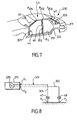
- Fig. 5 shows the transmitter 11 with output selection means in more details.
- the transmitter includes an electrical generator 30 which generates electrical current in the primary winding 32 of a current transformer 31.
- the electrical generator 30 can be designed as the driver circuit 56 of Fig. 1.
- the secondary winding 33 of transformer 31 is connectable to different pairs of the output terminals O 1 -O 5 through a switching device 34 comprising four contact relays A-D.
- Tuning capacitors C 1 -C 4 are connected between the relays A, B and D and the output terminals O 1 , O 3 and O 5 .
- a different capacitor is needed for tuning each hybrid loop if they have a different inductivity.
- Each contact relay has a default position denoted by 0 and an activated position denoted by 1.
- the relays A-D are controlled by the central unit of the system (not shown).
- Fig. 4 Possible transmission areas inside and outside the vehicle are shown in Fig. 4.
- Area 20 is inside the passenger compartment.
- Area 19 is inside the luggage compartment.
- Area 23 is outside the vehicle on the left-hand side.
- Area 24 is outside the vehicle behind the luggage compartment.
- Area 25 is outside the vehicle on the right-hand side.
- the hybrid loop antennas are driven sequentially as described in Table 1 with the same power level or with different levels.
- the process for locating the electronic key 12 is based on a measurement of the field amplitude at the electronic key reception antenna. Accordingly, every time it receives a signal, the electronic key 12 measures the field amplitude (i.e. an electric tension at the receiving antenna) and communicates that value to the on-board central unit, together with the antenna identification code as the case may be.
- the on-board central unit detects that the electronic key 12 is in one of the transmission areas when it receives a response to a signal which was transmitted using to the corresponding activated wires and when the corresponding field measurement condition is verified.
- Fig 6 shows a second embodiment 110 of the vehicle.
- the connection points P 3 and P 5 are modified to P' 3 and P' 5 in comparison to the first embodiment.
- the transmitter 111 is placed at the right-hand front comer of the vehicle compartment instead of the left-hand rear comer.
- the elements which are identical or analogous to those of the first embodiment are denoted by the same reference number increased by 100.
- the transmitter 111 is identical to the transmitter 11 of Fig. 5 and is connected to wire conductors 101-105 as shown in Fig. 5. Wire portions which follow the same path are preferably twisted or intertwined together.
- the transmission areas are substantially the same as in the first embodiment.
- the detection of the electronic key is carried out in the same manner, using the switching and detection rules shown in Table 2.
- the default position of the contact relays A-D is selected in such a manner that the antenna wire conductors which are excited in that position are those which cover a transmission zone located on the driver's lateral side of the vehicle (area 23), so that a faster response time is obtained when the driver requests access to the car by actuating the driver door handle.
- Fig 7 shows a third embodiment 210 of the vehicle.
- the doors are omitted for the sake of clarity.
- the elements which are identical or analogous to those of the first embodiment are denoted by the same reference number increased by 200.
- the transmitter 211 is placed on the left-hand side of the luggage compartment and has a circuitry similar to that shown on Fig. 5 with three output terminals to which wire conductors 201-203 are connected.
- Wire conductors 201 and 202 extend together along the left-hand side of the body floor 213 from the transmitter 211 up to a branching point B 3 located at the bottom of the left-hand central pillar 40.
- This first portion of wire conductors 201 and 202 forms an intertwined wire pair 222 with a regular helical intertwining in order to minimize the magnetic radiation of this portion.
- wire 201 extends along the body floor 213, along the front side of the front door frame 44 and up the left-hand front pillar 41 up to connection point P 201 .
- wire 202 runs along the central pillar 40 up to connection point P 202 .
- Wire 203 runs along the left-hand rear pillar 42 up to connection point P 203 .
- Connection points P 201 -P 203 are located on the left-hand side of the vehicle roof 43 so that electrical current can flow from one to the other.
- wire conductors 201 and 202 When wire conductors 201 and 202 are selected, a transmission area is obtained which covers substantially the front half of areas 20 and 23 shown on Fig. 4, as seen in lateral projection. When wire conductors 203 and 202 are selected, a transmission area is obtained which covers substantially the rear half of areas 20 and 23 as seen in lateral projection.
- the transmitter includes electrical driving means in the form of several driver circuits connected to different pairs of output terminals.
- the central control unit is provided with driver circuit selection means operable in several states for selectively activating the different driver circuits.
- a switching device such as device 34 is not needed in that case.
- the antenna wire conductors are fed through a transformer 31, which prevents any short-circuited connection between the driver circuit and the vehicle body from occurring.
- the modified transmitter 311 includes a low frequency generator 330 (e.g. 20 kHz or 125 kHz) with two output terminals O 1 and O 2 which are connected to the vehicle body at connection points P 1 and P 2 through wire conductors 301 and 302.
- Number 322 represents an intertwined portion.
- Capacitors 47 and 48 are arranged on each wire, for example at the connection points P 1 and P 2 , so as to avoid the risk of a short-circuited connection for DC current between the generator and the vehicle body. While only two antenna output terminals and antenna wire conductors are shown for the sake of conciseness, it is clear that any number of output terminals can be similarly connected to the car body. Again, the corresponding output selection means can take the form of a switching device arranged between a single driver circuit and a number of output terminals or the form of a number of selectable driver circuits or other forms.
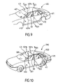
- Fig 9 shows a fourth embodiment 410 of the vehicle.
- the elements which are identical or analogous to those of the first embodiment are denoted by the same reference number increased by 400.
- the transmitter 411 is placed on the left-hand side of the luggage compartment and has output terminals to which insulated wire conductors 401 and 402 are connected. From the transmitter outputs up to a branching point B 401 located at the bottom of the left-hand central pillar 40, the wire conductors 401 and 402 extend together through a left-side body harness which extends longitudinally along the left-hand side of the body floor 413. This first portion of wire conductors 401 and 402 forms a twisted wire pair 422 with a regular helical intertwining in order to minimize the magnetic radiation of this portion.
- wire 401 has a portion 401 a which extends transversally across the vehicle on the body floor 413 and a portion 401b which runs along the right-hand central pillar up to connection point P 401 .
- wire 402 runs up the central pillar 40 up to connection point P 402 .
- Connection points P 401 and P 402 are located on the underside of the vehicle top 43 at opposite sides of the vehicle body. The vehicle top 43 makes an electrical connection between both sides of the vehicle.
- wires 401 and 402 form a hybrid loop antenna which surrounds the passenger compartment as seen in longitudinal projection.
- a similar hybrid loop antenna is obtained in the vehicle 510 shown on Fig. 10, where elements which are identical or analogous to those of the first embodiment are denoted by the same reference number increased by 500.
- the intertwined wire pair 522 runs along the left-hand rear pillar 42 of the vehicle body and along the left-hand side of the vehicle body top 43 up to branching point B 501 which is located at the top of the left-hand central pillar 40.
- the insulated wire 501 has a portion 501 a which extends transversally across the vehicle on the underside of the vehicle top 43 and a portion 501b which runs along the right-hand central pillar down to connection point P 501 .
- connection points P 501 and P 502 are located on the body floor 513 at opposite sides of the vehicle body.
- the body floor 513 makes an electrical connection between both sides of the vehicle.
- the hybrid loop antennas of Fig. 9 and 10 can also be made at the front end or at the rear end of the passenger compartment by passing the wires along the front or rear pillars of the vehicle body instead of the centre pillars.
- the pair of wires 401/402 or 501/502 shown on Figs. 9 and 10 can be used as the only transmission antenna of the system, in which case only two transmitter outputs are needed. They can also be combined with other hybrid loops as shown in the preceding embodiments, in which case the transmitter will be fitted with more outputs and include output selection means, as described above.
- the position of the central control unit with the transmitter and the positions and number of the connection points need not be the same as the illustrative embodiments shown in the figures.
- the path of the antenna wire conductors can be easily adapted to any desired position of the transmitter because suitable locations for connection points are available on most parts of any vehicle body and because intertwined wire pairs can be formed wherever a wire portion is not intended to radiate.
- the proposed antenna architecture offers great flexibility.
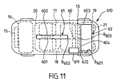
- the transmitter 611 has two output terminals which feed two series-connected loop antennas 61 and 62 which are entirely made of insulated electrical wire.
- the loop antennas 61 and 62 are arranged in such a manner that their respective transmission areas substantially coincide with the passenger compartment 20 and the luggage compartment area 19, respectively.
- Loop antenna 61 is located on the body floor 13 at the centre of the passenger compartment 20, i.e. around the transmission tunnel and gear box.
- Loop antenna 62 is located on the body floor 13 around the luggage compartment area 19, as seen from above on Fig. 11. Both loops are series-connected through an intertwined wire pair 60, which does not affect the radiation pattern of each loop.
- An intertwined wire pair 622 is also used for connecting loop antenna 62 to the transmitter output terminals.
- intertwined wire pair 622 extends from the transmitter output terminals to a first branching point B 601 where two wire portions 603 and 604 separate from one another.
- Wire portions 603 and 604 extend along the sides of the luggage compartment 19 in mutually opposite directions down to meeting point B 603 which is located in the middle of the vehicle at the front side of the luggage compartment. From points B 601 to B 603 ; wire portions 603 and 604 form loop antenna 62.
- wire portions 603 and 604 join to form an intertwined wire pair 622 which extends longitudinally along the body floor 13 down to a second branching point B 602 where two wire portions 601 and 602 separate from one another.
- wire portions 601 and 602 extend along opposite lateral sides of the transmission tunnel and are connected to one another at the front end of the passenger compartment so as to constitute loop antenna 62.
- Both loop antennas and both intertwined wire pairs can be made with a single uninterrupted wire. They can also be made of a number of shorter wire portions which are series-connected with appropriate connectors, in order to simplify the installation of the antenna assembly. As a preference, the corresponding wire or wire portions are placed in the wiring harnesses of the vehicle. Alternatively, they can be connected through one or more standard connectors between different on-board system modules of the vehicle.
- Transmitter 611 includes an antenna driver circuit, which can be similar to that shown on Fig. 1, i.e. with an electrical current transformer for impedance matching.
- More than two series-connected loop antennas can be formed similarly.
- a very simple and cost-effective antenna assembly is obtained, which provides a number of well-defined transmission areas, because the intertwined wire portions not affect the radiation pattern of the loop antennas, while making it possible to use a simple driver circuit with two output terminals.
- the invention is also applicable to keyless ignition systems.
Landscapes
- Engineering & Computer Science (AREA)
- Remote Sensing (AREA)
- Computer Security & Cryptography (AREA)
- Radar, Positioning & Navigation (AREA)
- Lock And Its Accessories (AREA)
- Details Of Aerials (AREA)
- Support Of Aerials (AREA)
- Aerials With Secondary Devices (AREA)
- Variable-Direction Aerials And Aerial Arrays (AREA)
Priority Applications (1)
| Application Number | Priority Date | Filing Date | Title |
|---|---|---|---|
| EP04077304A EP1533865B1 (de) | 2003-11-03 | 2004-07-05 | Bordseitiger Signalgeber zur Durchführung schlüssellosen Zugangs |
Applications Claiming Priority (2)
| Application Number | Priority Date | Filing Date | Title |
|---|---|---|---|
| GBGB0325577.5A GB0325577D0 (en) | 2003-11-03 | 2003-11-03 | Antenna system |
| GB0325577 | 2003-11-03 |
Related Child Applications (1)
| Application Number | Title | Priority Date | Filing Date |
|---|---|---|---|
| EP04077304A Division EP1533865B1 (de) | 2003-11-03 | 2004-07-05 | Bordseitiger Signalgeber zur Durchführung schlüssellosen Zugangs |
Publications (2)
| Publication Number | Publication Date |
|---|---|
| EP1548871A1 true EP1548871A1 (de) | 2005-06-29 |
| EP1548871B1 EP1548871B1 (de) | 2006-06-07 |
Family
ID=29725821
Family Applications (2)
| Application Number | Title | Priority Date | Filing Date |
|---|---|---|---|
| EP04077304A Expired - Lifetime EP1533865B1 (de) | 2003-11-03 | 2004-07-05 | Bordseitiger Signalgeber zur Durchführung schlüssellosen Zugangs |
| EP04291697A Expired - Lifetime EP1548871B1 (de) | 2003-11-03 | 2004-07-05 | Bordseitiger Signalgeber zur Durchführung schlüssellosen Zuganges |
Family Applications Before (1)
| Application Number | Title | Priority Date | Filing Date |
|---|---|---|---|
| EP04077304A Expired - Lifetime EP1533865B1 (de) | 2003-11-03 | 2004-07-05 | Bordseitiger Signalgeber zur Durchführung schlüssellosen Zugangs |
Country Status (4)
| Country | Link |
|---|---|
| EP (2) | EP1533865B1 (de) |
| AT (2) | ATE329379T1 (de) |
| DE (2) | DE602004011449T2 (de) |
| GB (1) | GB0325577D0 (de) |
Cited By (3)
| Publication number | Priority date | Publication date | Assignee | Title |
|---|---|---|---|---|
| DE102005032379A1 (de) * | 2005-07-08 | 2007-01-11 | Conti Temic Microelectronic Gmbh | Zugangskontrollsystem für ein Kraftfahrzeug |
| EP1750326A1 (de) * | 2005-08-01 | 2007-02-07 | Delphi Technologies, Inc. | Antenneneinrichtung |
| EP1777532A1 (de) * | 2005-10-18 | 2007-04-25 | Delphi Technologies, Inc. | Prüfverfahren und Treibereinrichtung für eine Antenne |
Families Citing this family (2)
| Publication number | Priority date | Publication date | Assignee | Title |
|---|---|---|---|---|
| DE102005015594B4 (de) * | 2005-04-05 | 2007-04-12 | Texas Instruments Deutschland Gmbh | Berührungsloses Zugangssystem und Wegfahrsperre mit unterschiedlichen Frequenzen unter Verwendung derselben Antennenspule |
| DE102006042344A1 (de) * | 2006-09-08 | 2008-04-03 | Conti Temic Microelectronic Gmbh | Funkanordnung in einem Fahrzeug |
Citations (6)
| Publication number | Priority date | Publication date | Assignee | Title |
|---|---|---|---|---|
| US4873530A (en) * | 1985-09-30 | 1989-10-10 | Nissan Motor Co., Ltd. | Antenna device in automotive keyless entry system |
| US5812095A (en) * | 1995-10-06 | 1998-09-22 | Ford Motor Company | Mounting structure for combined automotive trim accessory and antenna |
| WO1999023716A1 (de) * | 1997-10-31 | 1999-05-14 | Siemens Aktiengesellschaft | Antennenvorrichtung,insbesondere für ein diebstahlschutzsystem eines kraftfahrzeugs |
| EP1014479A1 (de) * | 1997-11-25 | 2000-06-28 | Ford Global Technologies, Inc., A subsidiary of Ford Motor Company | Antennenanordnung für schlüssellose Benutzung eines Fahrzeuges |
| EP1184236A2 (de) * | 2000-08-30 | 2002-03-06 | Omron Corporation | Funksystem |
| US20020027498A1 (en) * | 2000-07-03 | 2002-03-07 | Etter Stephane | Automobile vehicle equipped with a sophisticated "hands-off" access system to determine the localization of a portable badge |
-
2003
- 2003-11-03 GB GBGB0325577.5A patent/GB0325577D0/en not_active Ceased
-
2004
- 2004-07-05 DE DE602004011449T patent/DE602004011449T2/de not_active Expired - Lifetime
- 2004-07-05 AT AT04291697T patent/ATE329379T1/de not_active IP Right Cessation
- 2004-07-05 EP EP04077304A patent/EP1533865B1/de not_active Expired - Lifetime
- 2004-07-05 AT AT04077304T patent/ATE385053T1/de not_active IP Right Cessation
- 2004-07-05 EP EP04291697A patent/EP1548871B1/de not_active Expired - Lifetime
- 2004-07-05 DE DE602004001122T patent/DE602004001122T2/de not_active Expired - Lifetime
Patent Citations (6)
| Publication number | Priority date | Publication date | Assignee | Title |
|---|---|---|---|---|
| US4873530A (en) * | 1985-09-30 | 1989-10-10 | Nissan Motor Co., Ltd. | Antenna device in automotive keyless entry system |
| US5812095A (en) * | 1995-10-06 | 1998-09-22 | Ford Motor Company | Mounting structure for combined automotive trim accessory and antenna |
| WO1999023716A1 (de) * | 1997-10-31 | 1999-05-14 | Siemens Aktiengesellschaft | Antennenvorrichtung,insbesondere für ein diebstahlschutzsystem eines kraftfahrzeugs |
| EP1014479A1 (de) * | 1997-11-25 | 2000-06-28 | Ford Global Technologies, Inc., A subsidiary of Ford Motor Company | Antennenanordnung für schlüssellose Benutzung eines Fahrzeuges |
| US20020027498A1 (en) * | 2000-07-03 | 2002-03-07 | Etter Stephane | Automobile vehicle equipped with a sophisticated "hands-off" access system to determine the localization of a portable badge |
| EP1184236A2 (de) * | 2000-08-30 | 2002-03-06 | Omron Corporation | Funksystem |
Cited By (3)
| Publication number | Priority date | Publication date | Assignee | Title |
|---|---|---|---|---|
| DE102005032379A1 (de) * | 2005-07-08 | 2007-01-11 | Conti Temic Microelectronic Gmbh | Zugangskontrollsystem für ein Kraftfahrzeug |
| EP1750326A1 (de) * | 2005-08-01 | 2007-02-07 | Delphi Technologies, Inc. | Antenneneinrichtung |
| EP1777532A1 (de) * | 2005-10-18 | 2007-04-25 | Delphi Technologies, Inc. | Prüfverfahren und Treibereinrichtung für eine Antenne |
Also Published As
| Publication number | Publication date |
|---|---|
| ATE385053T1 (de) | 2008-02-15 |
| EP1548871B1 (de) | 2006-06-07 |
| DE602004011449T2 (de) | 2009-01-15 |
| EP1533865A1 (de) | 2005-05-25 |
| ATE329379T1 (de) | 2006-06-15 |
| DE602004001122D1 (de) | 2006-07-20 |
| DE602004001122T2 (de) | 2007-01-04 |
| EP1533865B1 (de) | 2008-01-23 |
| GB0325577D0 (en) | 2003-12-03 |
| DE602004011449D1 (de) | 2008-03-13 |
Similar Documents
| Publication | Publication Date | Title |
|---|---|---|
| US20050159131A1 (en) | Communicator and vehicle controller | |
| US6563474B2 (en) | Remote access device having multiple inductive coil antenna | |
| US8614645B2 (en) | Antenna module for a motor vehicle | |
| EP0590955A2 (de) | Antenne für mehrere Frequenzbereiche | |
| US20150145646A1 (en) | Keyless entry system | |
| US10777875B2 (en) | Detection device and detection system | |
| EP1548871B1 (de) | Bordseitiger Signalgeber zur Durchführung schlüssellosen Zuganges | |
| US6965352B2 (en) | Antenna device for vehicles and vehicle antenna system and communication system using the antenna device | |
| KR20170039653A (ko) | 자동차의 보드 상에 있는 휴대용 요소와 근거리 무선 주파수 통신을 하기 위한 디바이스 | |
| US6392607B1 (en) | Antenna system especially for an anti-theft system of a motor vehicle | |
| JP2019062372A (ja) | 複合アンテナ装置 | |
| JP5088026B2 (ja) | スマートキーレスエントリシステム | |
| JPH06177625A (ja) | 自動車用ガラスアンテナ | |
| US6937197B2 (en) | Antenna for a central locking system of an automotive vehicle | |
| JP2019062373A (ja) | 複合アンテナ装置 | |
| JP2004244851A (ja) | リモートコントロールシステム | |
| JP2017123572A (ja) | アンテナ装置 | |
| CN113661300B (zh) | 为车辆的门把手电子装置提供至少一个功能的装置 | |
| EP0398710B1 (de) | Diversity-Empfangsgerät | |
| US20240322423A1 (en) | Antenna device | |
| JP2008078971A (ja) | 車載用の無線受信装置および無線受信装置の設定方法 | |
| JP4638814B2 (ja) | 通信装置 | |
| US20190362112A1 (en) | Detection device and detection system | |
| JP7855138B2 (ja) | 層状の近距離無線通信アンテナ | |
| JP3069067B2 (ja) | 自動車用ガラスアンテナ装置 |
Legal Events
| Date | Code | Title | Description |
|---|---|---|---|
| PUAI | Public reference made under article 153(3) epc to a published international application that has entered the european phase |
Free format text: ORIGINAL CODE: 0009012 |
|
| 17P | Request for examination filed |
Effective date: 20050430 |
|
| AK | Designated contracting states |
Kind code of ref document: A1 Designated state(s): AT BE BG CH CY CZ DE DK EE ES FI FR GB GR HU IE IT LI LU MC NL PL PT RO SE SI SK TR |
|
| AX | Request for extension of the european patent |
Extension state: AL HR LT LV MK |
|
| GRAP | Despatch of communication of intention to grant a patent |
Free format text: ORIGINAL CODE: EPIDOSNIGR1 |
|
| AKX | Designation fees paid |
Designated state(s): AT BE BG CH CY CZ DE DK EE ES FI FR GB GR HU IE IT LI LU MC NL PL PT RO SE SI SK TR |
|
| GRAS | Grant fee paid |
Free format text: ORIGINAL CODE: EPIDOSNIGR3 |
|
| GRAA | (expected) grant |
Free format text: ORIGINAL CODE: 0009210 |
|
| AK | Designated contracting states |
Kind code of ref document: B1 Designated state(s): AT BE BG CH CY CZ DE DK EE ES FI FR GB GR HU IE IT LI LU MC NL PL PT RO SE SI SK TR |
|
| PG25 | Lapsed in a contracting state [announced via postgrant information from national office to epo] |
Ref country code: NL Free format text: LAPSE BECAUSE OF FAILURE TO SUBMIT A TRANSLATION OF THE DESCRIPTION OR TO PAY THE FEE WITHIN THE PRESCRIBED TIME-LIMIT Effective date: 20060607 Ref country code: RO Free format text: LAPSE BECAUSE OF FAILURE TO SUBMIT A TRANSLATION OF THE DESCRIPTION OR TO PAY THE FEE WITHIN THE PRESCRIBED TIME-LIMIT Effective date: 20060607 Ref country code: CH Free format text: LAPSE BECAUSE OF FAILURE TO SUBMIT A TRANSLATION OF THE DESCRIPTION OR TO PAY THE FEE WITHIN THE PRESCRIBED TIME-LIMIT Effective date: 20060607 Ref country code: CZ Free format text: LAPSE BECAUSE OF FAILURE TO SUBMIT A TRANSLATION OF THE DESCRIPTION OR TO PAY THE FEE WITHIN THE PRESCRIBED TIME-LIMIT Effective date: 20060607 Ref country code: AT Free format text: LAPSE BECAUSE OF FAILURE TO SUBMIT A TRANSLATION OF THE DESCRIPTION OR TO PAY THE FEE WITHIN THE PRESCRIBED TIME-LIMIT Effective date: 20060607 Ref country code: FI Free format text: LAPSE BECAUSE OF FAILURE TO SUBMIT A TRANSLATION OF THE DESCRIPTION OR TO PAY THE FEE WITHIN THE PRESCRIBED TIME-LIMIT Effective date: 20060607 Ref country code: SI Free format text: LAPSE BECAUSE OF FAILURE TO SUBMIT A TRANSLATION OF THE DESCRIPTION OR TO PAY THE FEE WITHIN THE PRESCRIBED TIME-LIMIT Effective date: 20060607 Ref country code: PL Free format text: LAPSE BECAUSE OF FAILURE TO SUBMIT A TRANSLATION OF THE DESCRIPTION OR TO PAY THE FEE WITHIN THE PRESCRIBED TIME-LIMIT Effective date: 20060607 Ref country code: BE Free format text: LAPSE BECAUSE OF FAILURE TO SUBMIT A TRANSLATION OF THE DESCRIPTION OR TO PAY THE FEE WITHIN THE PRESCRIBED TIME-LIMIT Effective date: 20060607 Ref country code: LI Free format text: LAPSE BECAUSE OF FAILURE TO SUBMIT A TRANSLATION OF THE DESCRIPTION OR TO PAY THE FEE WITHIN THE PRESCRIBED TIME-LIMIT Effective date: 20060607 Ref country code: SK Free format text: LAPSE BECAUSE OF FAILURE TO SUBMIT A TRANSLATION OF THE DESCRIPTION OR TO PAY THE FEE WITHIN THE PRESCRIBED TIME-LIMIT Effective date: 20060607 |
|
| REG | Reference to a national code |
Ref country code: GB Ref legal event code: FG4D |
|
| REG | Reference to a national code |
Ref country code: CH Ref legal event code: EP |
|
| PG25 | Lapsed in a contracting state [announced via postgrant information from national office to epo] |
Ref country code: IE Free format text: LAPSE BECAUSE OF NON-PAYMENT OF DUE FEES Effective date: 20060705 |
|
| REG | Reference to a national code |
Ref country code: IE Ref legal event code: FG4D |
|
| REF | Corresponds to: |
Ref document number: 602004001122 Country of ref document: DE Date of ref document: 20060720 Kind code of ref document: P |
|
| PG25 | Lapsed in a contracting state [announced via postgrant information from national office to epo] |
Ref country code: MC Free format text: LAPSE BECAUSE OF NON-PAYMENT OF DUE FEES Effective date: 20060731 |
|
| PG25 | Lapsed in a contracting state [announced via postgrant information from national office to epo] |
Ref country code: DK Free format text: LAPSE BECAUSE OF FAILURE TO SUBMIT A TRANSLATION OF THE DESCRIPTION OR TO PAY THE FEE WITHIN THE PRESCRIBED TIME-LIMIT Effective date: 20060907 Ref country code: SE Free format text: LAPSE BECAUSE OF FAILURE TO SUBMIT A TRANSLATION OF THE DESCRIPTION OR TO PAY THE FEE WITHIN THE PRESCRIBED TIME-LIMIT Effective date: 20060907 |
|
| PG25 | Lapsed in a contracting state [announced via postgrant information from national office to epo] |
Ref country code: ES Free format text: LAPSE BECAUSE OF FAILURE TO SUBMIT A TRANSLATION OF THE DESCRIPTION OR TO PAY THE FEE WITHIN THE PRESCRIBED TIME-LIMIT Effective date: 20060918 |
|
| PG25 | Lapsed in a contracting state [announced via postgrant information from national office to epo] |
Ref country code: PT Free format text: LAPSE BECAUSE OF FAILURE TO SUBMIT A TRANSLATION OF THE DESCRIPTION OR TO PAY THE FEE WITHIN THE PRESCRIBED TIME-LIMIT Effective date: 20061107 |
|
| ET | Fr: translation filed | ||
| NLV1 | Nl: lapsed or annulled due to failure to fulfill the requirements of art. 29p and 29m of the patents act | ||
| REG | Reference to a national code |
Ref country code: CH Ref legal event code: PL |
|
| PLBE | No opposition filed within time limit |
Free format text: ORIGINAL CODE: 0009261 |
|
| STAA | Information on the status of an ep patent application or granted ep patent |
Free format text: STATUS: NO OPPOSITION FILED WITHIN TIME LIMIT |
|
| 26N | No opposition filed |
Effective date: 20070308 |
|
| PG25 | Lapsed in a contracting state [announced via postgrant information from national office to epo] |
Ref country code: GR Free format text: LAPSE BECAUSE OF FAILURE TO SUBMIT A TRANSLATION OF THE DESCRIPTION OR TO PAY THE FEE WITHIN THE PRESCRIBED TIME-LIMIT Effective date: 20060908 |
|
| PG25 | Lapsed in a contracting state [announced via postgrant information from national office to epo] |
Ref country code: EE Free format text: LAPSE BECAUSE OF FAILURE TO SUBMIT A TRANSLATION OF THE DESCRIPTION OR TO PAY THE FEE WITHIN THE PRESCRIBED TIME-LIMIT Effective date: 20060607 Ref country code: BG Free format text: LAPSE BECAUSE OF FAILURE TO SUBMIT A TRANSLATION OF THE DESCRIPTION OR TO PAY THE FEE WITHIN THE PRESCRIBED TIME-LIMIT Effective date: 20060907 |
|
| PG25 | Lapsed in a contracting state [announced via postgrant information from national office to epo] |
Ref country code: HU Free format text: LAPSE BECAUSE OF FAILURE TO SUBMIT A TRANSLATION OF THE DESCRIPTION OR TO PAY THE FEE WITHIN THE PRESCRIBED TIME-LIMIT Effective date: 20061208 Ref country code: TR Free format text: LAPSE BECAUSE OF FAILURE TO SUBMIT A TRANSLATION OF THE DESCRIPTION OR TO PAY THE FEE WITHIN THE PRESCRIBED TIME-LIMIT Effective date: 20060607 Ref country code: LU Free format text: LAPSE BECAUSE OF NON-PAYMENT OF DUE FEES Effective date: 20060705 |
|
| PG25 | Lapsed in a contracting state [announced via postgrant information from national office to epo] |
Ref country code: CY Free format text: LAPSE BECAUSE OF FAILURE TO SUBMIT A TRANSLATION OF THE DESCRIPTION OR TO PAY THE FEE WITHIN THE PRESCRIBED TIME-LIMIT Effective date: 20060607 |
|
| GBPC | Gb: european patent ceased through non-payment of renewal fee |
Effective date: 20080705 |
|
| PG25 | Lapsed in a contracting state [announced via postgrant information from national office to epo] |
Ref country code: GB Free format text: LAPSE BECAUSE OF NON-PAYMENT OF DUE FEES Effective date: 20080705 |
|
| REG | Reference to a national code |
Ref country code: FR Ref legal event code: TP Owner name: DELPHI INTERNATIONAL OPERATIONS LUXEMBOURG S.A, LU Effective date: 20131218 |
|
| REG | Reference to a national code |
Ref country code: DE Ref legal event code: R081 Ref document number: 602004001122 Country of ref document: DE Owner name: DELPHI INTERNATIONAL OPERATIONS LUXEMBOURG S.A, LU Free format text: FORMER OWNER: DELPHI TECHNOLOGIES, INC., TROY, US Effective date: 20140410 Ref country code: DE Ref legal event code: R082 Ref document number: 602004001122 Country of ref document: DE Representative=s name: REITSTOETTER KINZEBACH, DE Effective date: 20140410 Ref country code: DE Ref legal event code: R081 Ref document number: 602004001122 Country of ref document: DE Owner name: DELPHI INTERNATIONAL OPERATIONS LUXEMBOURG S.A, LU Free format text: FORMER OWNER: DELPHI TECHNOLOGIES, INC., TROY, MICH., US Effective date: 20140410 |
|
| REG | Reference to a national code |
Ref country code: FR Ref legal event code: PLFP Year of fee payment: 13 |
|
| REG | Reference to a national code |
Ref country code: FR Ref legal event code: PLFP Year of fee payment: 14 |
|
| REG | Reference to a national code |
Ref country code: FR Ref legal event code: PLFP Year of fee payment: 15 |
|
| REG | Reference to a national code |
Ref country code: DE Ref legal event code: R081 Ref document number: 602004001122 Country of ref document: DE Owner name: APTIV TECHNOLOGIES LIMITED, BB Free format text: FORMER OWNER: DELPHI INTERNATIONAL OPERATIONS LUXEMBOURG S.A R.L., 4940 HAUTCHARAGE, LU Ref country code: DE Ref legal event code: R082 Ref document number: 602004001122 Country of ref document: DE Ref country code: DE Ref legal event code: R081 Ref document number: 602004001122 Country of ref document: DE Owner name: APTIV TECHNOLOGIES LIMITED, BB Free format text: FORMER OWNER: DELPHI INTERNATIONAL OPERATIONS LUXEMBOURG S.A R.L., 4940 BASCHARAGE, LU |
|
| PGFP | Annual fee paid to national office [announced via postgrant information from national office to epo] |
Ref country code: IT Payment date: 20190726 Year of fee payment: 16 Ref country code: FR Payment date: 20190725 Year of fee payment: 16 |
|
| PG25 | Lapsed in a contracting state [announced via postgrant information from national office to epo] |
Ref country code: FR Free format text: LAPSE BECAUSE OF NON-PAYMENT OF DUE FEES Effective date: 20200731 |
|
| PG25 | Lapsed in a contracting state [announced via postgrant information from national office to epo] |
Ref country code: IT Free format text: LAPSE BECAUSE OF NON-PAYMENT OF DUE FEES Effective date: 20200705 |
|
| P01 | Opt-out of the competence of the unified patent court (upc) registered |
Effective date: 20230425 |
|
| PGFP | Annual fee paid to national office [announced via postgrant information from national office to epo] |
Ref country code: DE Payment date: 20230725 Year of fee payment: 20 |
|
| REG | Reference to a national code |
Ref country code: DE Ref legal event code: R071 Ref document number: 602004001122 Country of ref document: DE |