EP1548852A2 - Oberflächenemittierendes Licht aussendendes Halbleiterbauelement aus einer Nitridverbindung und Verfahren zu seiner Herstellung - Google Patents
Oberflächenemittierendes Licht aussendendes Halbleiterbauelement aus einer Nitridverbindung und Verfahren zu seiner Herstellung Download PDFInfo
- Publication number
- EP1548852A2 EP1548852A2 EP04257783A EP04257783A EP1548852A2 EP 1548852 A2 EP1548852 A2 EP 1548852A2 EP 04257783 A EP04257783 A EP 04257783A EP 04257783 A EP04257783 A EP 04257783A EP 1548852 A2 EP1548852 A2 EP 1548852A2
- Authority
- EP
- European Patent Office
- Prior art keywords
- layer
- transparent conductive
- thin film
- ohmic contact
- conductive thin
- Prior art date
- Legal status (The legal status is an assumption and is not a legal conclusion. Google has not performed a legal analysis and makes no representation as to the accuracy of the status listed.)
- Granted
Links
Images

Classifications
-
- H—ELECTRICITY
- H10—SEMICONDUCTOR DEVICES; ELECTRIC SOLID-STATE DEVICES NOT OTHERWISE PROVIDED FOR
- H10H—INORGANIC LIGHT-EMITTING SEMICONDUCTOR DEVICES HAVING POTENTIAL BARRIERS
- H10H20/00—Individual inorganic light-emitting semiconductor devices having potential barriers, e.g. light-emitting diodes [LED]
- H10H20/80—Constructional details
- H10H20/83—Electrodes
- H10H20/832—Electrodes characterised by their material
- H10H20/833—Transparent materials
-
- H—ELECTRICITY
- H10—SEMICONDUCTOR DEVICES; ELECTRIC SOLID-STATE DEVICES NOT OTHERWISE PROVIDED FOR
- H10H—INORGANIC LIGHT-EMITTING SEMICONDUCTOR DEVICES HAVING POTENTIAL BARRIERS
- H10H20/00—Individual inorganic light-emitting semiconductor devices having potential barriers, e.g. light-emitting diodes [LED]
- H10H20/80—Constructional details
- H10H20/81—Bodies
- H10H20/822—Materials of the light-emitting regions
- H10H20/824—Materials of the light-emitting regions comprising only Group III-V materials, e.g. GaP
- H10H20/825—Materials of the light-emitting regions comprising only Group III-V materials, e.g. GaP containing nitrogen, e.g. GaN
Definitions
- the present invention relates to a top-emitting N-based light emitting device and a method of manufacturing the same, and more particularly, to a top-emitting N-based light emitting device, which has improved ohmic characteristic and luminous efficiency, and a method of manufacturing the same.
- Transparent conductive oxides TCOs
- TCN transparent conductive nitride
- TCOs are, for example, indium oxide (In 2 O 3 ), tin oxide (SnO 2 ), zinc oxide (ZnO), and indium tin oxide (ITO), and TCN is, for example, titanium nitride (TiN).
- TCOs or TCN have a high sheet resistance, a high reflectivity, and a small work function. Thus, it is difficult to apply only one of the TCOs and TCN to a p-type transparent electrode of a top-emitting GaN-based light emitting device.
- the thin film when a thin film is formed of one of the above-described TCOs or TCN using physical vapor deposition (PVD), an e-beam or heat evaporator, or sputtering, the thin film has a high sheet resistance of about 100 ⁇ / ⁇ .
- PVD physical vapor deposition
- e-beam or heat evaporator or sputtering
- the thin film has a high sheet resistance of about 100 ⁇ / ⁇ .
- Such a high sheet resistance of the thin film is an obstacle to the horizontal (parallel to an interfacial surface between films) current spreading of a light emitting device and the efficient vertical hole injection. Accordingly, it is difficult to apply one of the above-described transparent conductive materials to highly luminous light emitting devices, which have large area and high capacity.
- the above-described transparent conductive materials have a high reflectivity with respect to light emitted from GaN-based light emitting diodes, thus degrading luminous efficiency.
- transparent conductive materials including ITO and TiN have a relatively small work function, it is difficult to form an ohmic contact between the transparent conductive materials and p-type GaN.
- Ga 2 O 3 which is an insulating material, is generated on the surface of GaN due to a high oxidation activity of Ga. This precludes formation of a good ohmic-contact electrode.
- a light emitting device such as a light emitting diode (LED) or a laser diode (LD)
- LED light emitting diode
- LD laser diode
- GaN-based light emitting devices can be categorized into top-emitting light emitting diodes (TLEDs) and flip-chip light emitting diodes (FCLEDs).
- TLEDs top-emitting light emitting diodes
- FCLEDs flip-chip light emitting diodes
- a current spreading layer as an excellent ohmic contact layer is essentially required to compensate for a high sheet resistance of a p-type clad layer having a low hole concentration. Since the current spreading layer has a low sheet resistance and a high transmittance, smooth hole injection and current spreading and efficient light emission are enabled.
- a conventional TLED includes a Ni layer and an Au layer, which are sequentially stacked on a p-type clad layer.
- a semi-transparent ohmic contact layer which has an excellent specific contact resistance of about 10 -3 to 10 -4 ⁇ cm 2 .
- the semi-transparent ohmic contact layer is annealed in an O 2 atmosphere at a temperature of about 500 to 600 °C, the low specific contact resistance of the semi-transparent ohmic contact layer reduces Schottky barrier height (SBH) and thus, facilitates supply of carriers, i.e., holes, to the vicinity of the surface of the p-type clad layer.
- SBH Schottky barrier height
- the Ni/Au layer formed on the p-type clad layer is annealed, reactivation occurs.
- the dopant concentration of Mg in the surface of GaN is increased by removing Mg-H intermetal compounds, so that the effective carrier concentration in the surface of the p-type clad layer exceeds 10 18 .
- a tunneling phenomenon occurs between the p-type clad layer and the ohmic contact layer containing nickel oxide and thus, the ohmic contact layer has a low specific contact resistance.
- a TLED having a semi-transparent thin-film electrode formed of Ni/Au contains Au, which degrades transmittance.
- the TLED has a low luminous efficiency and thus, cannot be one of the next-generation light emitting devices that have a high capacity and a high luminance.
- an FCLED includes a reflective film and radiates light through a transparent substrate formed of sapphire in order to increase heat emission and luminous efficiency during the driving of the FCLED.
- the FCLED has a high resistance due to oxidation and poor adhesion of the reflective film.
- these ohmic contact layers can increase the output power of light emitting devices, they require relatively high operating voltages. Accordingly, since many problems still remain unsolved, the foregoing ohmic contact layers cannot be readily applied to light emitting devices that have a large area, a high capacity, and a high luminance.
- LumiLeds Lighting has reported that an LED having a high transmittance and excellent electrical characteristics was manufactured by combining oxidized thin Ni/Au (or Ni/Ag) and ITO [US Patent No. 6,287,947 by Michael J. Ludowise etc.].
- an ohmic-contact electrode forming process is very complicated, and because an ohmic electrode formed of transitional metals including Ni or oxides of elements of the group II of the Mendeleev Periodic Table has a high sheet resistance, it is difficult to embody a highly efficient light emitting device. Further, it is known that oxides of metals including Ni hardly have a high transmittance.
- p-type GaN has a low hole concentration and thus, has a high sheet resistance of 104 ⁇ / ⁇ or higher.
- a transparent electrode having a high transmittance generally has a high sheet resistance so that horizontal current spreading is remarkably degraded.
- Ga 2 O 3 which is an insulating material, is produced on the surface of the GaN, thus deteriorating the electrical characteristics of a light emitting device.
- a top-emitting N-based light emitting device which includes an active layer between an n-type clad layer and a p-type clad layer.
- the light emitting device includes a multi ohmic contact layer including one or more stacked structures, each including a modified metal layer and a transparent conductive thin film layer, and the stacked structures are repetitively stacked on the p-type clad layer.
- the modified metal layer is formed of an Ag-based material.
- the transparent conductive thin film layer may be formed of a combination of O and at least one selected from the group consisting of In, Sn, Zn, Ga, Cd, Mg, Be, Ag, Mo, V, Cu, Ir, Rh, Ru, W, Co, Ni, Mn, Al, and Ln (lanthanized series).
- the transparent conductive thin film layer may be formed of TiN.
- the modified metal layer may have a thickness of about 1 to 20 nm.
- the transparent conductive thin film layer may have a thickness of about 10 to 1000 nm.
- a metal interposed layer may be additionally disposed between the modified metal layer and the transparent conductive thin film layer.
- the metal interposed layer may be formed of at least one selected from the group consisting of Pt, Ni, Au, Ru, Pd, Rh, Ir, Zn, Mg, Cr, Cu, Co, In, Sn, Ln, an alloy or solid solution thereof, and nitrides of transitional metals.
- a method of manufacturing a top-emitting N-based light emitting device which includes an active layer between an n-type clad layer and a p-type clad layer.
- a multi ohmic contact layer is formed by repetitively stacking one or more stacked structures, each including a modified metal layer and a transparent conductive thin film layer, on the p-type clad layer of a light emitting structure including the n-type clad layer, the active layer, and the p-type clad layer that are sequentially stacked on a substrate. Thereafter, the multi ohmic contact layer is annealed.
- the modified metal layer is formed of Ag.
- the transparent conductive thin film layer may be formed of a TCO or TCN, which is added by at least one of metals of the Mendeleev periodic table, in order to improve the electrical characteristics thereof.
- the annealing of the multi ohmic contact layer may be performed at a temperature between a room temperature and 800 °C for 10 seconds to 3 hours.
- At least one of N, Ar, He, O 2 , H 2 , and air may be injected into a reactor in which the multi ohmic contact layer is loaded.
- the present invention provides a top-emitting GaN-based light emitting device, which includes an electrode having a high transmittance and a low sheet resistance, and a method of manufacturing the same.
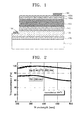
- FIG. 1 is a cross-sectional view of a top-emitting light emitting device according to an embodiment of the present invention.
- the top-emitting light emitting device includes a substrate 110, a buffer layer 120, an n-type clad layer 130, an active layer 140, a p-type clad layer 150, and a multi ohmic contact layer 160, which are sequentially stacked.
- Reference numeral 180 denotes a p-type electrode pad, and 190 denotes an n-type electrode pad.
- the multi ohmic contact layer 160 includes a modified metal layer 160a and a transparent conductive thin film layer 160b, which are sequentially stacked.
- a stacked structure including the substrate 110, the buffer layer 120, the n-type clad layer 130, the active layer 140, and the p-type clad layer corresponds to a light emitting structure, and the multi ohmic contact layer 160 corresponds to a p-type electrode structure.
- the substrate 110 may be formed of one selected from the group consisting of sapphire (Al 2 O 3 ), silicon carbide (SiC), silicon (Si), and gallium arsenide (GaAs).
- the buffer layer 120 may be optically formed.
- Each of the buffer layer 120, the n-type clad layer 130, the active layer 140, and the p-type clad layer 150 is basically formed of a III-group N-based compound (Al x ln y Ga z N (0 ⁇ x ⁇ 1, 0 ⁇ y ⁇ 1, 0 ⁇ z ⁇ 1, and 0 ⁇ x+y+z ⁇ 1 )), and each of the n- and p-type clad layers 130 and 150 is doped with a certain dopant.
- the active layer 140 may be a film having one of various known structures, for example, a single film or a multiple quantum well (MQW) film.
- MQW multiple quantum well
- the buffer layer 120 may be formed of GaN
- the n-type clad layer 130 may be formed of GaN doped with an n-type dopant, such as Si, Ge, Se, and Te
- the active layer 140 may be formed of InGaN/GaN MQW or AIGaN/GaN MQW
- the p-type clad layer 150 may be formed of GaN doped with a p-type dopant, such as Mg, Zn, Ca, Sr, and Ba.
- n-type ohmic contact layer (not shown) may be interposed between the n-type clad layer 130 and the n-type electrode pad 190.
- the n-type ohmic contact layer may have various known structures, for example, a stacked structure of Ti and AI.
- the p-type electrode pad 180 may have a stacked structure of Ni/Au or Ag/Au.
- Each of the above-described films may be formed using a known deposition method, such as an e-beam evaporator, PVD, chemical vapor deposition (CVD), plasma laser deposition (PLD), a dual-type thermal evaporator, or sputtering.
- a known deposition method such as an e-beam evaporator, PVD, chemical vapor deposition (CVD), plasma laser deposition (PLD), a dual-type thermal evaporator, or sputtering.
- the multi ohmic contact layer 160 which is the p-type electrode structure, includes the modified metal layer 160a formed on the p-type clad layer 150 and the transparent conductive thin film layer 160b formed on the modified metal layer 160a.
- the modified metal layer 160a is formed of a material, which has a high electroconductivity, is easily decomposed into nano-phase grains due to annealing performed in an O 2 atmosphere at a temperature of 600 °C or lower, and is not easily oxidized. Considering the above-described conditions, the modified metal layer 160a may be formed of Ag.
- the modified metal layer 160a is preferably formed of only Ag. In another case, the modified metal layer 160a may be formed of an Ag-based alloy or solid solution.
- the modified metal layer 160a forming the multi ohmic contact layer 160 may be formed to a thickness of about 1 to 20 nm such that it can be easily decomposed into nano-phase grains due to annealing.
- the transparent conductive thin film layer 160b may be formed of one of TCO and TCN.
- the TCO is a combination of O and at least one selected from the group consisting of In, Sn, Zn, Ga, Cd, Mg, Be, Ag, Mo, V, Cu, Ir, Rh, Ru, W, Co, Ni, Mn, Al, and Ln (lanthanized series).
- the transparent conductive thin film layer 160b is formed of TCO, the work function and sheet resistance of the TCO are considered above all.
- the transparent conductive thin film layer 160b is formed of a TCN, TiN, which has a low sheet resistance and a high transmittance, is preferred.
- the transparent conductive thin film layer 160b can be formed of a TCO or TCN, which is added by at least one of metals of the Mendeleev periodic table, in order to improve the electrical characteristics thereof.
- an addition ratio of the added metal to the TCO or TCN may be in the range of 0.001 to 20 weight %.
- the transparent conductive thin film layer 160b may be formed to a thickness of about 10 to 1000 nm.
- the multi ohmic contact layer 160 may be formed using one of an e-beam evaporator, a thermal evaporator, sputtering, and PLD.
- the multi ohmic contact layer 160 can be deposited at a temperature of about 20 to 1500 °C under a pressure of an atmospheric pressure to about 10 -12 torr.
- the formation of the multi ohmic contact layer 160 may be followed by annealing.
- the annealing is performed in vacuum or gaseous atmosphere at a temperature of about 100 to 800 °C for 10 seconds to 3 hours.
- At least one of N, Ar, He, O 2 , H 2 , and air may be injected into a reactor.
- FIG. 2 is a graph of transmittance versus wavelength in light emitting devices using the multi ohmic contact layer 160 as a p-type electrode shown in FIG. 1 and a single transparent electrode film, respectively.
- a modified metal layer 160a was formed on a p-type clad layer 150 using Ag to a thickness of 3 nm
- a transparent conductive thin film layer 160b was stacked thereon using ITO to a thickness of about 200 nm
- the resultant structure was annealed at a temperature of 530°C.
- the single transparent electrode film was formed by stacking ITO on a p-type clad layer 150 to a thickness of about 200 nm and annealing the ITO film at a temperature of 530°C.
- the multi ohmic contact layer 160 has a higher transmittance than the single electrode film formed of ITO.
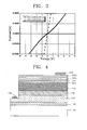
- FIG. 3 is a graph of current versus voltage in light emitting devices using the multi ohmic contact layer 160 shown in FIG. 1 and a film formed of Au instead of Ag, respectively.
- a modified metal layer 160a was formed on a p-type clad layer 150 using Ag to a thickness of 3 nm, a transparent conductive thin film layer 160b was stacked thereon using SnO 2 to a thickness of 200 nm, and the resultant structure was annealed at a temperature of 530 °C.
- an Au film was stacked on a p-type clad layer 150 to a thickness of 3 nm, and a transparent conductive thin film layer was stacked thereon using SnO 2 to a thickness of 200 nm, and the resultant structure was annealed at the same temperature, i.e., 530°C.
- the multi ohmic contact layer 160 when the multi ohmic contact layer 160 was formed by sequentially stacking the Ag modified metal layer 160a and the transparent conductive thin film layer 160b and annealing the stacked films, a lot of advantages can be obtained. Specifically, gallide is formed between the p-type clad layer 150 and the modified metal layer 160a so that effective surface hole concentration increases, and the generation of Ga 2 O 3 is suppressed so that the width of Schottky barrier is reduced. Also, a tunneling phenomenon occurs to facilitate formation of ohmic contact. Further, even if the multi ohmic contact layer 160 is annealed at a low temperature of 600 °C or lower, a high transmittance can be maintained. In addition, the multi ohmic contact layer 160 has a low sheet resistance of about 10 ⁇ / ⁇ or lower.
- the multi ohmic contact layer 160 can be formed by repetitively stacking one or more stacked structures, each including the modified metal layer 160a and the transparent conductive thin film layer 160b.
- FIG. 4 A multi ohmic contact layer according to another embodiment of the present invention, in which two or more stacked structures, each including a modified metal layer and a transparent conductive thin film layer, are repetitively stacked, is illustrated in FIG. 4.
- the same reference numerals are used to denote the same elements as in FIG. 1.
- a multi ohmic contact layer 160 includes a first modified metal layer 160a, a first transparent conductive thin film layer 160b, a second modified metal layer 160c, and a second transparent conductive thin film layer 160d, which are sequentially stacked.
- Each of the first and second modified metal layers 160a and 160c is formed of Ag or an Ag-based alloy or solid solution to a thickness of about 1 to 20 nm.
- Each of the first and second transparent conductive thin film layers 160b and 160d is formed of the above-described materials to a thickness of about 10 to 1000 nm.
- the multi ohmic contact layer 160 as a p-type electrode structure is deposited on a light emitting structure including a substrate 110, a buffer layer 120, an n-type clad layer 130, an active layer 140, a p-type clad layer 150, which are sequentially stacked.
- the multi ohmic contact layer 160 is deposited on the light emitting structure using the method as described with reference to FIG. 1. Thereafter, the resultant structure is annealed, thereby manufacturing a light emitting device shown in FIG. 4.
- the light emitting device can have improved transmittance and current-voltage (I-V) characteristic.
- FIG. 5 is a cross-sectional view of a top-emitting light emitting device including a multi ohmic contact layer according to yet another embodiment of the present invention.
- the multi ohmic contact layer as a p-type electrode additionally includes a metal interposed layer 160e between a modified metal layer 160a and a transparent conductive thin film layer 160b.
- the metal interposed layer 160e is formed as a second modified metal layer that performs substantially the same function as the modified metal layer 160a.
- the metal interposed layer 160e may be formed of at least one selected from the group consisting of Pt, Ni, Au, Ru, Pd, Rh, Ir, Zn, Mg, Cr, Cu, Co, In, Sn, Ln, an alloy or solid solution thereof, and nitrides of transitional metals.
- FIG. 6A is a graph of current versus voltage in a light emitting device using the multi ohmic contact layer shown in FIG. 5.
- a modified metal layer 160a was formed of Ag to a thickness of 1 nm
- a metal interposed layer 160e was formed of Pt to a thickness of 1 nm
- a transparent conductive thin film layer 160b was formed of ITO to a thickness of 200 nm.
- the I-V characteristic of the light emitting device using the multi ohmic contact layer was respectively measured as-dep ( ⁇ ) and after an annealing process was performed in an air atmosphere at 500 °C(•), 600 °C( ⁇ ), and 700 °C( ⁇ ). It can be observed from FIG. 6 that when the multi ohmic contact layer was annealed at 600 °C or higher, it exhibited a very excellent electrical characteristic.
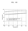
- FIG. 6B is a graph of transmittance versus wavelength in light emitting devices using the multi ohmic contact layer shown in FIG. 5 and a conventional electrode, respectively.
- a modified metal layer 160a was formed of Ag to a thickness of 1 nm
- a metal interposed layer 160e was formed of Pt to a thickness of 1 nm
- a transparent conductive thin film layer 160b was formed of ITO to a thickness of 200 nm. Thereafter, the resultant structure was annealed in an air atmosphere at about 600 °C for 1 minute.
- the conventional electrode was formed by stacking a 5-nm Ni film and a 5-nm Au film and annealing the stacked films in an air atmosphere at 530 °C for 1 minute. It can be observed from FIG. 6B that when the conventional electrode was used, transmittance was about 73 to 81 % in the wavelength range of 450 to 500 nm. However, when the p-type electrode according to the present invention was used, transmittance exceeded 90% in the same wavelength range.
- a top-emitting N-based light emitting device of the present invention an ohmic contact characteristic between an ohmic contact layer and a p-type clad layer is improved.
- the light emitting device can have not only an excellent I-V characteristic but also high luminous efficiency.
Landscapes
- Led Devices (AREA)
- Electrodes Of Semiconductors (AREA)
Applications Claiming Priority (4)
| Application Number | Priority Date | Filing Date | Title |
|---|---|---|---|
| KR20030094698 | 2003-12-22 | ||
| KR2003094698 | 2003-12-22 | ||
| KR2004088166 | 2004-11-02 | ||
| KR1020040088166A KR100601971B1 (ko) | 2003-12-22 | 2004-11-02 | 탑에미트형 질화물계 발광소자 및 그 제조방법 |
Publications (3)
| Publication Number | Publication Date |
|---|---|
| EP1548852A2 true EP1548852A2 (de) | 2005-06-29 |
| EP1548852A3 EP1548852A3 (de) | 2006-12-27 |
| EP1548852B1 EP1548852B1 (de) | 2013-07-10 |
Family
ID=34555005
Family Applications (1)
| Application Number | Title | Priority Date | Filing Date |
|---|---|---|---|
| EP04257783.3A Expired - Lifetime EP1548852B1 (de) | 2003-12-22 | 2004-12-15 | Oberflächenemittierendes Licht aussendendes Halbleiterbauelement aus einer Nitridverbindung und Verfahren zu seiner Herstellung |
Country Status (4)
| Country | Link |
|---|---|
| US (2) | US7417264B2 (de) |
| EP (1) | EP1548852B1 (de) |
| JP (1) | JP5084099B2 (de) |
| CN (1) | CN100411199C (de) |
Cited By (3)
| Publication number | Priority date | Publication date | Assignee | Title |
|---|---|---|---|---|
| DE102005046450A1 (de) * | 2005-09-28 | 2007-04-05 | Osram Opto Semiconductors Gmbh | Optoelektronischer Halbleiterchip, Verfahren zu dessen Herstellung und optoelektronisches Bauteil |
| EP2005488A4 (de) * | 2005-12-16 | 2011-02-16 | Samsung Electronics Co Ltd | Optische anordnung und verfahren zu ihrer herstellung |
| WO2015015113A1 (fr) * | 2013-08-01 | 2015-02-05 | Saint-Gobain Glass France | Fabrication d'une electrode grille par demouillage d'argent |
Families Citing this family (26)
| Publication number | Priority date | Publication date | Assignee | Title |
|---|---|---|---|---|
| US20050274964A1 (en) * | 2004-05-29 | 2005-12-15 | Ting-Kai Huang | Light emitting diode structure |
| WO2006009413A1 (en) * | 2004-07-23 | 2006-01-26 | Gwangju Institute Of Science And Technology | Top-emitting light emitting diodes and method of manufacturing thereof |
| KR100878433B1 (ko) * | 2005-05-18 | 2009-01-13 | 삼성전기주식회사 | 발광소자의 오믹컨택층 제조방법 및 이를 이용한발광소자의 제조방법 |
| KR100706507B1 (ko) * | 2005-06-02 | 2007-04-11 | 엘지전자 주식회사 | 디지털 비디오 녹화 및 재생 장치에서의 복수의 타이틀복사 방법 |
| KR100833489B1 (ko) * | 2006-02-21 | 2008-05-29 | 한국전자통신연구원 | 실리콘 나노 점을 이용한 반도체 발광 소자 및 그 제조방법 |
| KR100755649B1 (ko) * | 2006-04-05 | 2007-09-04 | 삼성전기주식회사 | GaN계 반도체 발광소자 및 그 제조방법 |
| KR100853851B1 (ko) * | 2006-10-30 | 2008-08-22 | 삼성전기주식회사 | 질화물 반도체 발광소자 |
| CN101494261B (zh) * | 2008-01-23 | 2011-09-28 | 晶元光电股份有限公司 | 发光二极管元件、背光模块以及照明设备 |
| WO2010113237A1 (ja) * | 2009-04-03 | 2010-10-07 | パナソニック株式会社 | 窒化物系半導体素子およびその製造方法 |
| JP5332882B2 (ja) * | 2009-04-30 | 2013-11-06 | 豊田合成株式会社 | 半導体発光素子 |
| TWI377645B (en) * | 2009-05-07 | 2012-11-21 | Atomic Energy Council | Ohmic contact having silver material |
| US8502192B2 (en) * | 2010-01-12 | 2013-08-06 | Varian Semiconductor Equipment Associates, Inc. | LED with uniform current spreading and method of fabrication |
| JP5494005B2 (ja) * | 2010-02-26 | 2014-05-14 | 豊田合成株式会社 | 半導体発光素子 |
| US8933543B2 (en) | 2010-04-02 | 2015-01-13 | Panasonic Intellectual Property Management Co., Ltd. | Nitride semiconductor element having m-plane angled semiconductor region and electrode including Mg and Ag |
| CN201796942U (zh) * | 2010-05-28 | 2011-04-13 | 景德镇正宇奈米科技有限公司 | 具有透明导电热辐射散热薄膜的发光二极管结构 |
| JP5829014B2 (ja) * | 2010-09-30 | 2015-12-09 | シャープ株式会社 | 化合物半導体発光素子の製造方法 |
| JP2012124306A (ja) * | 2010-12-08 | 2012-06-28 | Toyoda Gosei Co Ltd | 半導体発光素子 |
| WO2013010190A2 (en) | 2011-07-14 | 2013-01-17 | Sumitomo Bakelite Co., Ltd. | A self-imageable layer forming polymer and compositions thereof |
| TWI529963B (zh) * | 2011-07-25 | 2016-04-11 | 廣鎵光電股份有限公司 | 發光元件結構 |
| DE102011115299B4 (de) * | 2011-09-29 | 2023-04-27 | OSRAM Opto Semiconductors Gesellschaft mit beschränkter Haftung | Optoelektronischer Halbleiterchip und Verfahren zur Herstellung eines optoelektronischen Halbleiterchips |
| CN102916100B (zh) | 2012-11-08 | 2015-04-08 | 安徽三安光电有限公司 | 发光二极管及其制作方法 |
| US20140268377A1 (en) * | 2013-03-13 | 2014-09-18 | Intermolecular, Inc. | Ultrathin Coating for One Way Mirror Applications |
| JP2014204000A (ja) * | 2013-04-05 | 2014-10-27 | 株式会社アルバック | 半導体装置 |
| US20150060910A1 (en) * | 2013-08-29 | 2015-03-05 | Intermolecular Inc. | Conductive Transparent Reflector |
| CN105633236B (zh) * | 2016-01-06 | 2019-04-05 | 厦门市三安光电科技有限公司 | 发光二极管及其制作方法 |
| CN105702828A (zh) * | 2016-04-07 | 2016-06-22 | 厦门乾照光电股份有限公司 | 一种复合透明导电层的制作工艺 |
Citations (3)
| Publication number | Priority date | Publication date | Assignee | Title |
|---|---|---|---|---|
| JPH09281517A (ja) | 1996-04-17 | 1997-10-31 | Hitachi Ltd | 透明導電膜および液晶表示装置 |
| US5990500A (en) | 1998-03-25 | 1999-11-23 | Kabushiki Kaisha Toshiba | Nitride compound semiconductor light emitting element and its manufacturing method |
| US6268618B1 (en) | 1997-05-08 | 2001-07-31 | Showa Denko K.K. | Electrode for light-emitting semiconductor devices and method of producing the electrode |
Family Cites Families (27)
| Publication number | Priority date | Publication date | Assignee | Title |
|---|---|---|---|---|
| JPS6010788A (ja) * | 1983-06-30 | 1985-01-19 | Kanegafuchi Chem Ind Co Ltd | 太陽電池用基板 |
| JPH0614554B2 (ja) * | 1985-03-22 | 1994-02-23 | 工業技術院長 | 薄膜太陽電池の製造方法 |
| JPS62176173A (ja) * | 1986-01-29 | 1987-08-01 | Semiconductor Energy Lab Co Ltd | 光電変換装置作成方法 |
| US5428249A (en) * | 1992-07-15 | 1995-06-27 | Canon Kabushiki Kaisha | Photovoltaic device with improved collector electrode |
| JPH07131070A (ja) * | 1993-10-28 | 1995-05-19 | Victor Co Of Japan Ltd | 半導体発光素子及び半導体発光素子アレイ |
| US6267947B1 (en) * | 1993-12-23 | 2001-07-31 | Sun Glitz Corporation | Water resistant pesticide composition |
| JP2992464B2 (ja) * | 1994-11-04 | 1999-12-20 | キヤノン株式会社 | 集電電極用被覆ワイヤ、該集電電極用被覆ワイヤを用いた光起電力素子及びその製造方法 |
| US5703436A (en) * | 1994-12-13 | 1997-12-30 | The Trustees Of Princeton University | Transparent contacts for organic devices |
| US5667853A (en) | 1995-03-22 | 1997-09-16 | Toppan Printing Co., Ltd. | Multilayered conductive film, and transparent electrode substrate and liquid crystal device using the same |
| US5861636A (en) * | 1995-04-11 | 1999-01-19 | Nec Corporation | Surface emitting visible light emiting diode having ring-shaped electrode |
| JP3009095B2 (ja) * | 1995-10-27 | 2000-02-14 | 日亜化学工業株式会社 | 窒化物半導体発光素子 |
| JP3207773B2 (ja) * | 1996-12-09 | 2001-09-10 | 株式会社東芝 | 化合物半導体発光素子及びその製造方法 |
| JPH114020A (ja) * | 1997-04-15 | 1999-01-06 | Toshiba Corp | 半導体発光素子及びその製造方法、並びに半導体発光装置 |
| DE69839300T2 (de) * | 1997-12-15 | 2009-04-16 | Philips Lumileds Lighting Company, LLC, San Jose | Licht-emittierende Vorrichtung |
| JP3469484B2 (ja) * | 1998-12-24 | 2003-11-25 | 株式会社東芝 | 半導体発光素子およびその製造方法 |
| US6597110B1 (en) * | 1999-05-13 | 2003-07-22 | The University Of Southern California | Titanium nitride anode for use in organic light emitting devices |
| TW437104B (en) * | 1999-05-25 | 2001-05-28 | Wang Tien Yang | Semiconductor light-emitting device and method for manufacturing the same |
| US6287947B1 (en) | 1999-06-08 | 2001-09-11 | Lumileds Lighting, U.S. Llc | Method of forming transparent contacts to a p-type GaN layer |
| TW439304B (en) * | 2000-01-05 | 2001-06-07 | Ind Tech Res Inst | GaN series III-V compound semiconductor devices |
| JP3398638B2 (ja) * | 2000-01-28 | 2003-04-21 | 科学技術振興事業団 | 発光ダイオードおよび半導体レーザーとそれらの製造方法 |
| TW497277B (en) * | 2000-03-10 | 2002-08-01 | Toshiba Corp | Semiconductor light emitting device and method for manufacturing the same |
| WO2001091254A2 (en) * | 2000-05-22 | 2001-11-29 | Massachusetts Institute Of Technology | Microcavity amplifiers |
| US6420736B1 (en) * | 2000-07-26 | 2002-07-16 | Axt, Inc. | Window for gallium nitride light emitting diode |
| JP2002185041A (ja) * | 2000-12-15 | 2002-06-28 | Nobuhiko Sawaki | 半導体素子 |
| US6558575B2 (en) * | 2001-02-07 | 2003-05-06 | Agfa-Gevaert | Perparation of improved ZnS:Mn phosphors |
| KR100720101B1 (ko) * | 2005-08-09 | 2007-05-18 | 삼성전자주식회사 | 나노구조의 다기능성 오믹층을 사용한 탑에미트형 질화물계발광소자 및 그 제조방법 |
| JP4655942B2 (ja) * | 2006-01-16 | 2011-03-23 | セイコーエプソン株式会社 | 発光装置、発光装置の製造方法および電子機器 |
-
2004
- 2004-12-15 US US11/011,154 patent/US7417264B2/en not_active Expired - Lifetime
- 2004-12-15 EP EP04257783.3A patent/EP1548852B1/de not_active Expired - Lifetime
- 2004-12-21 CN CNB2004100115942A patent/CN100411199C/zh not_active Expired - Lifetime
- 2004-12-21 JP JP2004369466A patent/JP5084099B2/ja not_active Expired - Fee Related
-
2008
- 2008-07-25 US US12/180,312 patent/US7666693B2/en not_active Expired - Lifetime
Patent Citations (3)
| Publication number | Priority date | Publication date | Assignee | Title |
|---|---|---|---|---|
| JPH09281517A (ja) | 1996-04-17 | 1997-10-31 | Hitachi Ltd | 透明導電膜および液晶表示装置 |
| US6268618B1 (en) | 1997-05-08 | 2001-07-31 | Showa Denko K.K. | Electrode for light-emitting semiconductor devices and method of producing the electrode |
| US5990500A (en) | 1998-03-25 | 1999-11-23 | Kabushiki Kaisha Toshiba | Nitride compound semiconductor light emitting element and its manufacturing method |
Cited By (7)
| Publication number | Priority date | Publication date | Assignee | Title |
|---|---|---|---|---|
| DE102005046450A1 (de) * | 2005-09-28 | 2007-04-05 | Osram Opto Semiconductors Gmbh | Optoelektronischer Halbleiterchip, Verfahren zu dessen Herstellung und optoelektronisches Bauteil |
| US7838876B2 (en) | 2005-09-28 | 2010-11-23 | Osram Opto Semiconductors Gmbh | Optoelectronic semiconductor device in which current spreading layer of sol gel material mixed with nanoparticles is mixed with wavelength conversion dyes |
| EP2005488A4 (de) * | 2005-12-16 | 2011-02-16 | Samsung Electronics Co Ltd | Optische anordnung und verfahren zu ihrer herstellung |
| US8487344B2 (en) | 2005-12-16 | 2013-07-16 | Samsung Display Co., Ltd. | Optical device and method of fabricating the same |
| WO2015015113A1 (fr) * | 2013-08-01 | 2015-02-05 | Saint-Gobain Glass France | Fabrication d'une electrode grille par demouillage d'argent |
| FR3009436A1 (fr) * | 2013-08-01 | 2015-02-06 | Saint Gobain | Fabrication d'une electrode grille par demouillage d'argent |
| CN105409029A (zh) * | 2013-08-01 | 2016-03-16 | 法国圣戈班玻璃厂 | 通过使银反润湿来制备栅电极 |
Also Published As
| Publication number | Publication date |
|---|---|
| EP1548852B1 (de) | 2013-07-10 |
| JP5084099B2 (ja) | 2012-11-28 |
| JP2005184001A (ja) | 2005-07-07 |
| US20080299687A1 (en) | 2008-12-04 |
| US20050133809A1 (en) | 2005-06-23 |
| US7417264B2 (en) | 2008-08-26 |
| CN100411199C (zh) | 2008-08-13 |
| US7666693B2 (en) | 2010-02-23 |
| CN1638155A (zh) | 2005-07-13 |
| EP1548852A3 (de) | 2006-12-27 |
Similar Documents
| Publication | Publication Date | Title |
|---|---|---|
| US7666693B2 (en) | Top-emitting nitride-based light emitting device and method of manufacturing the same | |
| US7964889B2 (en) | Nitride-based light-emitting device and method of manufacturing the same | |
| US8395176B2 (en) | Top-emitting nitride-based light-emitting device with ohmic characteristics and luminous efficiency | |
| US7485897B2 (en) | Nitride-based light-emitting device having grid cell layer | |
| US7372081B2 (en) | Nitride light emitting device and manufacturing method thereof | |
| US7193249B2 (en) | Nitride-based light emitting device and method of manufacturing the same | |
| US20070122925A1 (en) | Flip-chip nitride light emitting device and method of manufacturing thereof | |
| US20110018027A1 (en) | Top-emitting light emitting diodes and methods of manufacturing thereof | |
| CN101278409B (zh) | 倒装芯片发光二极管及其制备方法 | |
| KR100611642B1 (ko) | 탑에미트형 질화물계 발광소자 및 그 제조방법 | |
| KR100601971B1 (ko) | 탑에미트형 질화물계 발광소자 및 그 제조방법 | |
| KR100574104B1 (ko) | 플립칩형 질화물계 발광소자 및 그 제조방법 |
Legal Events
| Date | Code | Title | Description |
|---|---|---|---|
| PUAI | Public reference made under article 153(3) epc to a published international application that has entered the european phase |
Free format text: ORIGINAL CODE: 0009012 |
|
| AK | Designated contracting states |
Kind code of ref document: A2 Designated state(s): AT BE BG CH CY CZ DE DK EE ES FI FR GB GR HU IE IS IT LI LT LU MC NL PL PT RO SE SI SK TR |
|
| AX | Request for extension of the european patent |
Extension state: AL BA HR LV MK YU |
|
| PUAL | Search report despatched |
Free format text: ORIGINAL CODE: 0009013 |
|
| AK | Designated contracting states |
Kind code of ref document: A3 Designated state(s): AT BE BG CH CY CZ DE DK EE ES FI FR GB GR HU IE IS IT LI LT LU MC NL PL PT RO SE SI SK TR |
|
| AX | Request for extension of the european patent |
Extension state: AL BA HR LV MK YU |
|
| 17P | Request for examination filed |
Effective date: 20070328 |
|
| AKX | Designation fees paid |
Designated state(s): DE FR GB |
|
| 17Q | First examination report despatched |
Effective date: 20081205 |
|
| RAP1 | Party data changed (applicant data changed or rights of an application transferred) |
Owner name: GWANGJU INSTITUTE OF SCIENCE AND TECHNOLOGY Owner name: SAMSUNG ELECTRONICS CO., LTD. |
|
| REG | Reference to a national code |
Ref country code: DE Ref legal event code: R079 Ref document number: 602004042653 Country of ref document: DE Free format text: PREVIOUS MAIN CLASS: H01L0033000000 Ipc: H01L0033420000 |
|
| RIC1 | Information provided on ipc code assigned before grant |
Ipc: H01L 33/32 20100101ALI20121105BHEP Ipc: H01L 33/42 20100101AFI20121105BHEP |
|
| GRAP | Despatch of communication of intention to grant a patent |
Free format text: ORIGINAL CODE: EPIDOSNIGR1 |
|
| GRAP | Despatch of communication of intention to grant a patent |
Free format text: ORIGINAL CODE: EPIDOSNIGR1 |
|
| INTG | Intention to grant announced |
Effective date: 20130430 |
|
| GRAS | Grant fee paid |
Free format text: ORIGINAL CODE: EPIDOSNIGR3 |
|
| GRAA | (expected) grant |
Free format text: ORIGINAL CODE: 0009210 |
|
| AK | Designated contracting states |
Kind code of ref document: B1 Designated state(s): DE FR GB |
|
| REG | Reference to a national code |
Ref country code: GB Ref legal event code: FG4D |
|
| REG | Reference to a national code |
Ref country code: DE Ref legal event code: R096 Ref document number: 602004042653 Country of ref document: DE Effective date: 20130905 |
|
| PLBE | No opposition filed within time limit |
Free format text: ORIGINAL CODE: 0009261 |
|
| STAA | Information on the status of an ep patent application or granted ep patent |
Free format text: STATUS: NO OPPOSITION FILED WITHIN TIME LIMIT |
|
| 26N | No opposition filed |
Effective date: 20140411 |
|
| REG | Reference to a national code |
Ref country code: DE Ref legal event code: R097 Ref document number: 602004042653 Country of ref document: DE Effective date: 20140411 |
|
| REG | Reference to a national code |
Ref country code: FR Ref legal event code: ST Effective date: 20140829 |
|
| PG25 | Lapsed in a contracting state [announced via postgrant information from national office to epo] |
Ref country code: FR Free format text: LAPSE BECAUSE OF NON-PAYMENT OF DUE FEES Effective date: 20131231 |
|
| PGFP | Annual fee paid to national office [announced via postgrant information from national office to epo] |
Ref country code: GB Payment date: 20231026 Year of fee payment: 20 |
|
| PGFP | Annual fee paid to national office [announced via postgrant information from national office to epo] |
Ref country code: DE Payment date: 20231024 Year of fee payment: 20 |
|
| REG | Reference to a national code |
Ref country code: DE Ref legal event code: R079 Ref document number: 602004042653 Country of ref document: DE Free format text: PREVIOUS MAIN CLASS: H01L0033420000 Ipc: H10H0020833000 |
|
| REG | Reference to a national code |
Ref country code: DE Ref legal event code: R071 Ref document number: 602004042653 Country of ref document: DE |
|
| REG | Reference to a national code |
Ref country code: GB Ref legal event code: PE20 Expiry date: 20241214 |
|
| PG25 | Lapsed in a contracting state [announced via postgrant information from national office to epo] |
Ref country code: GB Free format text: LAPSE BECAUSE OF EXPIRATION OF PROTECTION Effective date: 20241214 |
|
| PG25 | Lapsed in a contracting state [announced via postgrant information from national office to epo] |
Ref country code: GB Free format text: LAPSE BECAUSE OF EXPIRATION OF PROTECTION Effective date: 20241214 |