EP1548773A1 - Chambre de soufflage pour un disjoncteur-protecteur possédant une double coupure - Google Patents
Chambre de soufflage pour un disjoncteur-protecteur possédant une double coupure Download PDFInfo
- Publication number
- EP1548773A1 EP1548773A1 EP03405921A EP03405921A EP1548773A1 EP 1548773 A1 EP1548773 A1 EP 1548773A1 EP 03405921 A EP03405921 A EP 03405921A EP 03405921 A EP03405921 A EP 03405921A EP 1548773 A1 EP1548773 A1 EP 1548773A1
- Authority
- EP
- European Patent Office
- Prior art keywords
- arc
- bridge
- quenching device
- magnetic
- circuit breaker
- Prior art date
- Legal status (The legal status is an assumption and is not a legal conclusion. Google has not performed a legal analysis and makes no representation as to the accuracy of the status listed.)
- Granted
Links
- 238000009434 installation Methods 0.000 title description 2
- 238000010791 quenching Methods 0.000 claims abstract description 19
- 238000007664 blowing Methods 0.000 claims abstract description 9
- 230000000171 quenching effect Effects 0.000 claims description 18
- 238000009413 insulation Methods 0.000 claims description 9
- 238000005192 partition Methods 0.000 claims description 3
- 239000012811 non-conductive material Substances 0.000 claims 1
- 230000003014 reinforcing effect Effects 0.000 claims 1
- 238000010891 electric arc Methods 0.000 abstract 3
- 239000004020 conductor Substances 0.000 description 5
- -1 NiCrMn Inorganic materials 0.000 description 4
- 230000001419 dependent effect Effects 0.000 description 4
- 239000007789 gas Substances 0.000 description 4
- 239000000463 material Substances 0.000 description 4
- XEEYBQQBJWHFJM-UHFFFAOYSA-N Iron Chemical compound [Fe] XEEYBQQBJWHFJM-UHFFFAOYSA-N 0.000 description 3
- 229910000831 Steel Inorganic materials 0.000 description 2
- 238000005253 cladding Methods 0.000 description 2
- 238000009826 distribution Methods 0.000 description 2
- 230000000694 effects Effects 0.000 description 2
- 229910052742 iron Inorganic materials 0.000 description 2
- 238000000034 method Methods 0.000 description 2
- 238000000465 moulding Methods 0.000 description 2
- 229920000642 polymer Polymers 0.000 description 2
- 239000010959 steel Substances 0.000 description 2
- CVOFKRWYWCSDMA-UHFFFAOYSA-N 2-chloro-n-(2,6-diethylphenyl)-n-(methoxymethyl)acetamide;2,6-dinitro-n,n-dipropyl-4-(trifluoromethyl)aniline Chemical compound CCC1=CC=CC(CC)=C1N(COC)C(=O)CCl.CCCN(CCC)C1=C([N+]([O-])=O)C=C(C(F)(F)F)C=C1[N+]([O-])=O CVOFKRWYWCSDMA-UHFFFAOYSA-N 0.000 description 1
- OKTJSMMVPCPJKN-UHFFFAOYSA-N Carbon Chemical compound [C] OKTJSMMVPCPJKN-UHFFFAOYSA-N 0.000 description 1
- 229910003321 CoFe Inorganic materials 0.000 description 1
- RYGMFSIKBFXOCR-UHFFFAOYSA-N Copper Chemical compound [Cu] RYGMFSIKBFXOCR-UHFFFAOYSA-N 0.000 description 1
- 229910001030 Iron–nickel alloy Inorganic materials 0.000 description 1
- 229910016006 MoSi Inorganic materials 0.000 description 1
- 229910003266 NiCo Inorganic materials 0.000 description 1
- 229910003289 NiMn Inorganic materials 0.000 description 1
- 229920005372 Plexiglas® Polymers 0.000 description 1
- 230000001133 acceleration Effects 0.000 description 1
- 230000008033 biological extinction Effects 0.000 description 1
- 229910052799 carbon Inorganic materials 0.000 description 1
- 229910010293 ceramic material Inorganic materials 0.000 description 1
- VNNRSPGTAMTISX-UHFFFAOYSA-N chromium nickel Chemical compound [Cr].[Ni] VNNRSPGTAMTISX-UHFFFAOYSA-N 0.000 description 1
- 239000002131 composite material Substances 0.000 description 1
- 238000001816 cooling Methods 0.000 description 1
- 229910052802 copper Inorganic materials 0.000 description 1
- 239000010949 copper Substances 0.000 description 1
- 230000003628 erosive effect Effects 0.000 description 1
- 210000002837 heart atrium Anatomy 0.000 description 1
- 238000002347 injection Methods 0.000 description 1
- 239000007924 injection Substances 0.000 description 1
- 230000000670 limiting effect Effects 0.000 description 1
- 239000000696 magnetic material Substances 0.000 description 1
- 238000004519 manufacturing process Methods 0.000 description 1
- 239000011159 matrix material Substances 0.000 description 1
- 239000002184 metal Substances 0.000 description 1
- 229910052751 metal Inorganic materials 0.000 description 1
- 229910001092 metal group alloy Inorganic materials 0.000 description 1
- 239000000203 mixture Substances 0.000 description 1
- 230000005405 multipole Effects 0.000 description 1
- 229910001120 nichrome Inorganic materials 0.000 description 1
- 229910052759 nickel Inorganic materials 0.000 description 1
- 238000010943 off-gassing Methods 0.000 description 1
- 230000002688 persistence Effects 0.000 description 1
- 239000004926 polymethyl methacrylate Substances 0.000 description 1
- 238000007493 shaping process Methods 0.000 description 1
- 229910021332 silicide Inorganic materials 0.000 description 1
- FVBUAEGBCNSCDD-UHFFFAOYSA-N silicide(4-) Chemical compound [Si-4] FVBUAEGBCNSCDD-UHFFFAOYSA-N 0.000 description 1
Images
Classifications
-
- H—ELECTRICITY
- H01—ELECTRIC ELEMENTS
- H01H—ELECTRIC SWITCHES; RELAYS; SELECTORS; EMERGENCY PROTECTIVE DEVICES
- H01H9/00—Details of switching devices, not covered by groups H01H1/00 - H01H7/00
- H01H9/30—Means for extinguishing or preventing arc between current-carrying parts
- H01H9/44—Means for extinguishing or preventing arc between current-carrying parts using blow-out magnet
- H01H9/446—Means for extinguishing or preventing arc between current-carrying parts using blow-out magnet using magnetisable elements associated with the contacts
-
- H—ELECTRICITY
- H01—ELECTRIC ELEMENTS
- H01H—ELECTRIC SWITCHES; RELAYS; SELECTORS; EMERGENCY PROTECTIVE DEVICES
- H01H1/00—Contacts
- H01H1/12—Contacts characterised by the manner in which co-operating contacts engage
- H01H1/14—Contacts characterised by the manner in which co-operating contacts engage by abutting
- H01H1/20—Bridging contacts
- H01H1/2066—Fork-shaped bridge; Two transversally connected contact arms bridging two fixed contacts
-
- H—ELECTRICITY
- H01—ELECTRIC ELEMENTS
- H01H—ELECTRIC SWITCHES; RELAYS; SELECTORS; EMERGENCY PROTECTIVE DEVICES
- H01H9/00—Details of switching devices, not covered by groups H01H1/00 - H01H7/00
- H01H9/30—Means for extinguishing or preventing arc between current-carrying parts
- H01H9/44—Means for extinguishing or preventing arc between current-carrying parts using blow-out magnet
-
- H—ELECTRICITY
- H01—ELECTRIC ELEMENTS
- H01H—ELECTRIC SWITCHES; RELAYS; SELECTORS; EMERGENCY PROTECTIVE DEVICES
- H01H73/00—Protective overload circuit-breaking switches in which excess current opens the contacts by automatic release of mechanical energy stored by previous operation of a hand reset mechanism
- H01H73/02—Details
- H01H73/18—Means for extinguishing or suppressing arc
-
- H—ELECTRICITY
- H01—ELECTRIC ELEMENTS
- H01H—ELECTRIC SWITCHES; RELAYS; SELECTORS; EMERGENCY PROTECTIVE DEVICES
- H01H9/00—Details of switching devices, not covered by groups H01H1/00 - H01H7/00
- H01H9/30—Means for extinguishing or preventing arc between current-carrying parts
- H01H9/46—Means for extinguishing or preventing arc between current-carrying parts using arcing horns
Definitions
- the present invention relates to the field of power switches for Low-voltage distribution networks. It relates to an arc quenching device for Circuit breaker with double break according to the preamble of patent claim 1.
- installation switch-in switches serve the fast and easy Reliable protection of low-voltage cables, motors, apparatus and systems against the consequences of overload and short-circuit currents. They exhibit in the Generally a thermal actuator with a bimetal and a electromagnetic release with a coil and a punch on and off preferably a contact arrangement with double interruption.
- a normal circuit breaker has a contact point, which consists of a fixed and a movable contact piece is formed.
- the contact point is in one so-called pre-chamber, to which a quenching chamber with a Arc splitter stack connects.
- the base points of the arc are of the fixed contact piece and the movable contact piece via arc guide rails passed to the arc splitter stack.
- the arc widens immediately after the contact opening, and the inlet velocity of the arc in the Arc splitter stack is dependent on the so-called own blowing, i. the by the arc itself generated magnetic blowing field, the pressure conditions in the Arc, the shaping of the guide rails and the choice of contact material.
- EP-A-0 212 661 is a current limiter for medium or high voltage applications described in which an arc between two arc guide rails runs away from a switch. Due to the special design of the low-inductive Guide rails, the resistance in the arc is significantly increased, so that a series-connected disconnector the circuit can be interrupted easily. To accelerate the arc movement, this is due to the turn-off current itself magnetic field generated by a magnetic core around one of the guide rails is appropriate.
- Object of the present invention is in a circuit breaker with Double break the acceleration of the two by a shutdown movement of a Switching contact generated arc to optimize targeted. This task is done by an arc quenching device with the features of claim 1 and a Circuit breaker with the features of claim 10 solved.
- advantageous Embodiments are evident from the dependent claims.
- the core of the invention is, by a suitable magnetic sheath the magnetic fields in the arc and thus on the arc acting and this driving in the direction of the splitter stacks Lorentz force strengthen.
- the arc moves faster, the contact erosion is reduces and the Abschalt advantageous horritively increased.
- the inventive separate magnetic sheath need the arc guide itself no Magnetic properties have more and therefore can non-magnetic, the arc movement favoring copper are produced.
- the magnetic jacket made of steel for example, is realized, by a one-piece, one-sided open molding with U-profile so on a bridge-side Arc running rail is slipped, that the arc space or the Antechamber is completed on three sides by the molding. That on the arc acting magnetic field of the current flowing in the arc run-off current, i. the so-called own blowing, is thereby reinforced.
- a Easy to manufacture a molded part and onto the arc runner during the assembly process Attach is provided.
- a blow loop inserted in a only during the Shutdown of the circuit breaker current-carrying and the two arc comprehensive arc extinguishing a blow loop inserted.
- the latter is arranged in sections parallel to an arc track and is of a Flowed through which points in the same direction as the turn-off in the adjacent arc guide rail.
- the U-shaped magnetic sheath comprises or preferably also surrounds this rail parallel Blassch securedabites.
- the blown loop is geometrically or material technically with equipped with current-limiting features. Since the blown loop in nominal operation, i. When the switch contact is closed, no current flows, this affects the self-impedance the switch is not and hinders due to their low initial or cold resistance of a few m ⁇ also the commutation of the arc to the corresponding Arc run rails not. After commutation of both arcs is also the blow loop flows through current, as a result increases their impedance and limited the turn-off current.
- the blow loop is formed so that Both arcs are favored to a similar extent, for example by a with respect to the extinguishing chamber partition symmetrical design of the blow loop or by two electrically connected in parallel, each associated with an arc Blassch secured.
- each arc or two atria assigned a separate magnetic sheath, which at the same time as magnetic Shielding of the arcing space opposite to that in the other arcing space dominating magnetic fields.
- the U-shaped magnetic shell is through a pre-chamber insulation made of Plexiglas, for example, from the actual arc chamber separated. This will cause the arc to roll over prevents metallic coat.
- the insulation can outgassing properties have, i. Remove arc-extinguishing gases.
- the pre-chamber insulation has a in the arc region protruding bulge to reduce the prechamber volume.
- the Reduced volume will cause a pressure loss of the gases in the arc area counteracted and the arc prevented from broadening. especially the Feet of the arc remain compact and thereby heat the Arc guide rails, which is conducive to movement of the arc.
- the bulge preferably has a V-shaped profile which extends in the direction of Extinguishing chamber opens and follows approximately the contour of the guide rails. This will ensured that the two arc base points move at the same speed and the Arc itself before entering the quenching chamber beyond its maximum, through the Distance of arc guide rails given length expands. So all are Splitter plates equally involved in the division and extinction of the arc.
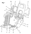
- Fig.1 shows in oblique view a section of a single or multi-pole Circuit breaker with two series-connected switching contacts per pole.
- a first Terminal 10 leads through the coil of a short-circuit current release 100 and a first connection conductor 11 to a first fixed contact 21. This is in closed Switch position (not shown) in electrical contact with a first bridge contact 31 of a movable fork-shaped contact bridge 3.
- a second bridge contact 32 of Contact bridge 3 is in closed switch position in contact with a second Fixed contact 22, which via a second connecting conductor 12 on to a not shown overcurrent release and leads to a second terminal. Both each formed by a fixed and bridge contact switching points is always a first or second pre-chamber 41,42 assigned.
- the inventive magnetic Sheath 91 with U-shaped cross-section which consists of a magnetically effective Material such as iron or steel preferably as a one-piece shielding plate is arranged so that it is the arc space, which between the first arc guide rails 51,61, laterally closes.
- a back 911 of the Jacket is located along the first bridge-side arc guide rail 61, while the side surfaces 912 of the shell towards the first connection side Arc guide rail 51 extend.
- the magnetic jacket 91 bundles this Arc magnetic field and drives the arc in addition in the direction of Chutes.
- each of the two prechambers 41, 42 is a separate one magnetic jacket 91.92 assigned. This will change the arc area between the both arc guide rails 51, 61; 52.61 magnetic with respect to the outside space and in particular with respect to the other prechamber 42; 41 shielded.
- Fig.1 between the first bridge-side running rail 61 and the second bridge-side Running rail 62, a first blower loop 81 is provided. In the event of triggering flows Abschaltstrom from the first to the second arc through this first blower loop 81.
- the blower loop 81 is preferably equipped with turn-off current limiting properties.
- a current-limiting behavior can be achieved, for example, by the selection of materials, all conductors with an electrical resistance in question, which increases with increasing current, and including in particular the known as PTC resistor (positive temperature coefficient) metallic alloys based on Ni, Co, Fe, such as NiCr, NiMn, NiFe, NiCrMn, NiCo, NiCoFe, CoFe, CrAlFe, or ceramic materials.
- PTC thermistor is based on a polymer composite whose polymer matrix is filled with a mixture of carbon, a metal such as Ni, and a boride, silicide, oxide or carbide such as TiC 2 , TiB 2 , MoSi 2 , V 2 O 3 . It is important that the initial or cold resistance is not too high and the commutation of the arcs on the bridge-side rails 61,62 and the concomitant training of the arc extinguishing circuit is not hindered.
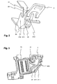
- Fig.3 a section through the first pre-chamber 41 is shown, whereby from the first magnetic cladding 91 only the cut surface of his back 911 is visible.
- the arc running properties are strongly dependent on the contour of the arc guide rails 51.61 dependent. Due to the apparent narrowing between the upper and lower Guide rail over a large part of the antechamber, the arc is optimal accelerated. Since in the widening of the guide rails 51, 61 the magnetic suction effect is already effective by the quenching plates 71 of magnetic material, is a Stability of the arc on the arc guide rails prevented and a instantaneous entry of the same possible.
- Prechamber insulation 411 Between the guide rails 51,61 and the magnetic jacket 91 is a Prechamber insulation 411, which has substantially the same cross section as the cladding 91 and this isolated from the arc region.
- a prechamber insulation as Injection molded part is suitably introduced before the assembly of the shell in this or slipped over the guardrails.
- a bulge 412 within the prechamber insulation directs the ionized gases on the guide rails, which are heated by the gases and let the arc base point run.
- the bulge 412 reduces the Distance perpendicular to the sectional plane of Figure 3 between the side surfaces of the insulation, i.e. the clear width of the arc chamber, by 30 to 50%.
- the bulge according to 3 has the shape of an elongated elevation, which is V-like in the direction of the Löschblechwovene 71 opens.
Landscapes
- Arc-Extinguishing Devices That Are Switches (AREA)
- Breakers (AREA)
- Driving Mechanisms And Operating Circuits Of Arc-Extinguishing High-Tension Switches (AREA)
Priority Applications (5)
| Application Number | Priority Date | Filing Date | Title |
|---|---|---|---|
| DE50309487T DE50309487D1 (de) | 2003-12-22 | 2003-12-22 | Lichtbogenlöscheinrichtung für Schutzschalter mit Doppelunterbrechung |
| AT03405921T ATE390700T1 (de) | 2003-12-22 | 2003-12-22 | Lichtbogenlöscheinrichtung für schutzschalter mit doppelunterbrechung |
| ES03405921T ES2302908T3 (es) | 2003-12-22 | 2003-12-22 | Dispositivo de extincion de arco electrico para interruptores de proteccion con interrupcion doble. |
| EP03405921A EP1548773B1 (fr) | 2003-12-22 | 2003-12-22 | Chambre de soufflage pour un disjoncteur-protecteur possédant une double coupure |
| US11/007,213 US7081596B2 (en) | 2003-12-22 | 2004-12-09 | Arc-quenching device for circuit breakers having double-break contacts |
Applications Claiming Priority (1)
| Application Number | Priority Date | Filing Date | Title |
|---|---|---|---|
| EP03405921A EP1548773B1 (fr) | 2003-12-22 | 2003-12-22 | Chambre de soufflage pour un disjoncteur-protecteur possédant une double coupure |
Publications (2)
| Publication Number | Publication Date |
|---|---|
| EP1548773A1 true EP1548773A1 (fr) | 2005-06-29 |
| EP1548773B1 EP1548773B1 (fr) | 2008-03-26 |
Family
ID=34530863
Family Applications (1)
| Application Number | Title | Priority Date | Filing Date |
|---|---|---|---|
| EP03405921A Expired - Lifetime EP1548773B1 (fr) | 2003-12-22 | 2003-12-22 | Chambre de soufflage pour un disjoncteur-protecteur possédant une double coupure |
Country Status (5)
| Country | Link |
|---|---|
| US (1) | US7081596B2 (fr) |
| EP (1) | EP1548773B1 (fr) |
| AT (1) | ATE390700T1 (fr) |
| DE (1) | DE50309487D1 (fr) |
| ES (1) | ES2302908T3 (fr) |
Cited By (1)
| Publication number | Priority date | Publication date | Assignee | Title |
|---|---|---|---|---|
| US9076606B2 (en) | 2011-11-04 | 2015-07-07 | Abb Schweiz Ag | Magnet arrangement for a low-voltage circuit-breaker |
Families Citing this family (13)
| Publication number | Priority date | Publication date | Assignee | Title |
|---|---|---|---|---|
| DE102005007303B4 (de) * | 2005-02-17 | 2013-03-21 | Abb Ag | Elektrisches Installationsgerät mit Lichtbogen-Vorkammerraum, Lichtbogenleitschienen und strombegrenzender Lichtbogenlöscheinrichtung |
| DE102006026064B4 (de) * | 2006-06-03 | 2008-06-05 | Moeller Gmbh | Elektrische Schaltanordnung und Montageverfahren |
| US7551050B2 (en) * | 2006-09-22 | 2009-06-23 | Rockwell Automation Technologies, Inc. | Contactor assembly with arc steering system |
| US7716816B2 (en) | 2006-09-22 | 2010-05-18 | Rockwell Automation Technologies, Inc. | Method of manufacturing a switch assembly |
| DE102009023556B4 (de) * | 2009-05-30 | 2012-01-19 | Abb Ag | Elektrisches Schaltgerät mit einem thermischen Auslöser |
| US8822866B2 (en) | 2010-04-19 | 2014-09-02 | Carling Technologies, Inc. | Circuit interrupter with enhanced arc quenching capabilities |
| WO2013070465A1 (fr) * | 2011-11-09 | 2013-05-16 | Eaton Corporation | Appareil de commutation électrique comprenant un ensemble aimant et des première et seconde chambres d'arc |
| DE102012212236A1 (de) * | 2012-07-12 | 2014-01-16 | Siemens Aktiengesellschaft | Schutzschaltgerät und Magnetjoch |
| US8809722B2 (en) * | 2012-10-11 | 2014-08-19 | Siemens Industry, Inc. | Circuit breaker with translating electrical contact, circuit breaker electrical contact assemblies, and operational methods |
| US9343251B2 (en) | 2013-10-30 | 2016-05-17 | Eaton Corporation | Bi-directional direct current electrical switching apparatus including small permanent magnets on ferromagnetic side members and one set of arc splitter plates |
| FR3023057B1 (fr) * | 2014-06-30 | 2016-07-22 | Hager-Electro Sas | Declencheur magnetothermique. |
| US10650993B1 (en) * | 2019-03-19 | 2020-05-12 | Siemens Industry, Inc. | Circuit breaker with enhanced arc extinguishing chamber |
| CN111755299B (zh) * | 2019-03-29 | 2022-07-05 | Ls产电株式会社 | 配线用断路器的灭弧装置 |
Citations (2)
| Publication number | Priority date | Publication date | Assignee | Title |
|---|---|---|---|---|
| EP0255016A1 (fr) * | 1986-07-31 | 1988-02-03 | Siemens Aktiengesellschaft | Elément interrupteur limitant le courant |
| EP0649155A1 (fr) * | 1993-10-15 | 1995-04-19 | Hager Electro S.A. | Tôle de conduction double pour chambre de conduction d'arc de disjoncteur |
Family Cites Families (4)
| Publication number | Priority date | Publication date | Assignee | Title |
|---|---|---|---|---|
| US4743720A (en) * | 1985-11-25 | 1988-05-10 | Matsushita Electric Works, Ltd. | Current limiting circuit interrupter |
| US4656446A (en) * | 1985-12-17 | 1987-04-07 | Westinghouse Electric Corp. | Current limiting circuit breaker with series double break contact system per pole |
| JPH071657B2 (ja) * | 1989-09-18 | 1995-01-11 | 三菱電機株式会社 | 回路遮断器 |
| US5694098A (en) * | 1996-05-20 | 1997-12-02 | Eaton Corporation | Rate of current rise sensitive slot motor and switching apparatus having current limiting contact arrangement incorporating said slot motor |
-
2003
- 2003-12-22 DE DE50309487T patent/DE50309487D1/de not_active Expired - Lifetime
- 2003-12-22 EP EP03405921A patent/EP1548773B1/fr not_active Expired - Lifetime
- 2003-12-22 ES ES03405921T patent/ES2302908T3/es not_active Expired - Lifetime
- 2003-12-22 AT AT03405921T patent/ATE390700T1/de not_active IP Right Cessation
-
2004
- 2004-12-09 US US11/007,213 patent/US7081596B2/en not_active Expired - Lifetime
Patent Citations (2)
| Publication number | Priority date | Publication date | Assignee | Title |
|---|---|---|---|---|
| EP0255016A1 (fr) * | 1986-07-31 | 1988-02-03 | Siemens Aktiengesellschaft | Elément interrupteur limitant le courant |
| EP0649155A1 (fr) * | 1993-10-15 | 1995-04-19 | Hager Electro S.A. | Tôle de conduction double pour chambre de conduction d'arc de disjoncteur |
Cited By (1)
| Publication number | Priority date | Publication date | Assignee | Title |
|---|---|---|---|---|
| US9076606B2 (en) | 2011-11-04 | 2015-07-07 | Abb Schweiz Ag | Magnet arrangement for a low-voltage circuit-breaker |
Also Published As
| Publication number | Publication date |
|---|---|
| DE50309487D1 (de) | 2008-05-08 |
| ES2302908T3 (es) | 2008-08-01 |
| EP1548773B1 (fr) | 2008-03-26 |
| US7081596B2 (en) | 2006-07-25 |
| ATE390700T1 (de) | 2008-04-15 |
| US20050150870A1 (en) | 2005-07-14 |
Similar Documents
| Publication | Publication Date | Title |
|---|---|---|
| EP3766090B1 (fr) | Disjoncteur de protection pour la coupure d'un circuit électrique | |
| EP1548773B1 (fr) | Chambre de soufflage pour un disjoncteur-protecteur possédant une double coupure | |
| DE69937107T2 (de) | Strombegrenzer und schalter mit strombegrenzungsfunktion | |
| EP1145265B1 (fr) | Dispositif de contact limitant le courant | |
| EP1615247B1 (fr) | Dispositif d'extinction d'arc électrique pour disjoncteur de protection | |
| DE102015217704A1 (de) | Lichtbogen-Löschvorrichtung und Schutzschaltgerät | |
| EP1693869A2 (fr) | Dispositif d'installation électrique avec préchambre d'extinction d'arc, séparateurs de préchambre et dispositif d'extinction d'arc à limitation de courant | |
| EP2079088A2 (fr) | Commutateur, notamment commutateur de puissance doté de deux paires de contacts commutés en série pour interrompre une voie de courant | |
| EP1683173B1 (fr) | Dispositif d'extinction d'arc | |
| EP3428942B1 (fr) | Dispositif d'extinction d'arc de courant continu et appareil de commutation de courant continu électromécanique | |
| EP2774158B1 (fr) | Commutateur pour un fonctionnement à courant continu multipolaire | |
| EP0350825B1 (fr) | Appareil de commutation électrique | |
| EP1548772A1 (fr) | Chambre de soufflage pour un disjoncteur-protecteur possèdant une double coupure | |
| DE102017204942B4 (de) | Elektromechanisches Schutzschaltgerät | |
| DE19903837B4 (de) | Selbsterholende Strombegrenzungseinrichtung mit Flüssigmetall | |
| EP2555217A1 (fr) | Système de limitation de courant | |
| DE10291133B4 (de) | Gehäuse für ein Schaltgerät | |
| EP1615246A1 (fr) | Dispositif d'extinction d'arc pour un disjoncteur | |
| EP3716304B1 (fr) | Interrupteur électrique permettant d'interrompre une connexion à haute voltage électrique et procédé d'interruption d'une connexion à haute voltage électrique | |
| DE102011002714A1 (de) | Schutzschaltgerät | |
| EP2541574B1 (fr) | Disjoncteur électrique à double point de rupture | |
| DE102012208573A1 (de) | Lichtbogen-Löschvorrichtung und Schutzschaltgerät | |
| DE19810981A1 (de) | Schalter mit PTC-Element zur verbesserten Strombegrenzung und Lichtbogenlöschung | |
| EP0614207A2 (fr) | Appareil de commutation avec un déclencheur thermique et magnétique | |
| WO2021023325A1 (fr) | Commutateur électrique pour ouvrir un trajet de courant |
Legal Events
| Date | Code | Title | Description |
|---|---|---|---|
| PUAI | Public reference made under article 153(3) epc to a published international application that has entered the european phase |
Free format text: ORIGINAL CODE: 0009012 |
|
| AK | Designated contracting states |
Kind code of ref document: A1 Designated state(s): AT BE BG CH CY CZ DE DK EE ES FI FR GB GR HU IE IT LI LU MC NL PT RO SE SI SK TR |
|
| AX | Request for extension of the european patent |
Extension state: AL LT LV MK |
|
| 17P | Request for examination filed |
Effective date: 20051110 |
|
| AKX | Designation fees paid |
Designated state(s): AT BE BG CH CY CZ DE DK EE ES FI FR GB GR HU IE IT LI LU MC NL PT RO SE SI SK TR |
|
| 17Q | First examination report despatched |
Effective date: 20070420 |
|
| GRAP | Despatch of communication of intention to grant a patent |
Free format text: ORIGINAL CODE: EPIDOSNIGR1 |
|
| GRAS | Grant fee paid |
Free format text: ORIGINAL CODE: EPIDOSNIGR3 |
|
| GRAA | (expected) grant |
Free format text: ORIGINAL CODE: 0009210 |
|
| AK | Designated contracting states |
Kind code of ref document: B1 Designated state(s): AT BE BG CH CY CZ DE DK EE ES FI FR GB GR HU IE IT LI LU MC NL PT RO SE SI SK TR |
|
| REG | Reference to a national code |
Ref country code: GB Ref legal event code: FG4D Free format text: NOT ENGLISH |
|
| REG | Reference to a national code |
Ref country code: CH Ref legal event code: EP Ref country code: IE Ref legal event code: FG4D Free format text: LANGUAGE OF EP DOCUMENT: GERMAN |
|
| REF | Corresponds to: |
Ref document number: 50309487 Country of ref document: DE Date of ref document: 20080508 Kind code of ref document: P |
|
| PG25 | Lapsed in a contracting state [announced via postgrant information from national office to epo] |
Ref country code: FI Free format text: LAPSE BECAUSE OF FAILURE TO SUBMIT A TRANSLATION OF THE DESCRIPTION OR TO PAY THE FEE WITHIN THE PRESCRIBED TIME-LIMIT Effective date: 20080326 |
|
| REG | Reference to a national code |
Ref country code: ES Ref legal event code: FG2A Ref document number: 2302908 Country of ref document: ES Kind code of ref document: T3 |
|
| NLV1 | Nl: lapsed or annulled due to failure to fulfill the requirements of art. 29p and 29m of the patents act | ||
| ET | Fr: translation filed | ||
| PG25 | Lapsed in a contracting state [announced via postgrant information from national office to epo] |
Ref country code: SI Free format text: LAPSE BECAUSE OF FAILURE TO SUBMIT A TRANSLATION OF THE DESCRIPTION OR TO PAY THE FEE WITHIN THE PRESCRIBED TIME-LIMIT Effective date: 20080326 |
|
| REG | Reference to a national code |
Ref country code: IE Ref legal event code: FD4D |
|
| PG25 | Lapsed in a contracting state [announced via postgrant information from national office to epo] |
Ref country code: CZ Free format text: LAPSE BECAUSE OF FAILURE TO SUBMIT A TRANSLATION OF THE DESCRIPTION OR TO PAY THE FEE WITHIN THE PRESCRIBED TIME-LIMIT Effective date: 20080326 Ref country code: SK Free format text: LAPSE BECAUSE OF FAILURE TO SUBMIT A TRANSLATION OF THE DESCRIPTION OR TO PAY THE FEE WITHIN THE PRESCRIBED TIME-LIMIT Effective date: 20080326 Ref country code: PT Free format text: LAPSE BECAUSE OF FAILURE TO SUBMIT A TRANSLATION OF THE DESCRIPTION OR TO PAY THE FEE WITHIN THE PRESCRIBED TIME-LIMIT Effective date: 20080901 Ref country code: SE Free format text: LAPSE BECAUSE OF FAILURE TO SUBMIT A TRANSLATION OF THE DESCRIPTION OR TO PAY THE FEE WITHIN THE PRESCRIBED TIME-LIMIT Effective date: 20080626 |
|
| PG25 | Lapsed in a contracting state [announced via postgrant information from national office to epo] |
Ref country code: RO Free format text: LAPSE BECAUSE OF FAILURE TO SUBMIT A TRANSLATION OF THE DESCRIPTION OR TO PAY THE FEE WITHIN THE PRESCRIBED TIME-LIMIT Effective date: 20080326 Ref country code: NL Free format text: LAPSE BECAUSE OF FAILURE TO SUBMIT A TRANSLATION OF THE DESCRIPTION OR TO PAY THE FEE WITHIN THE PRESCRIBED TIME-LIMIT Effective date: 20080326 |
|
| PG25 | Lapsed in a contracting state [announced via postgrant information from national office to epo] |
Ref country code: IE Free format text: LAPSE BECAUSE OF FAILURE TO SUBMIT A TRANSLATION OF THE DESCRIPTION OR TO PAY THE FEE WITHIN THE PRESCRIBED TIME-LIMIT Effective date: 20080326 Ref country code: DK Free format text: LAPSE BECAUSE OF FAILURE TO SUBMIT A TRANSLATION OF THE DESCRIPTION OR TO PAY THE FEE WITHIN THE PRESCRIBED TIME-LIMIT Effective date: 20080326 |
|
| PLBE | No opposition filed within time limit |
Free format text: ORIGINAL CODE: 0009261 |
|
| STAA | Information on the status of an ep patent application or granted ep patent |
Free format text: STATUS: NO OPPOSITION FILED WITHIN TIME LIMIT |
|
| 26N | No opposition filed |
Effective date: 20081230 |
|
| PG25 | Lapsed in a contracting state [announced via postgrant information from national office to epo] |
Ref country code: BG Free format text: LAPSE BECAUSE OF FAILURE TO SUBMIT A TRANSLATION OF THE DESCRIPTION OR TO PAY THE FEE WITHIN THE PRESCRIBED TIME-LIMIT Effective date: 20080626 Ref country code: EE Free format text: LAPSE BECAUSE OF FAILURE TO SUBMIT A TRANSLATION OF THE DESCRIPTION OR TO PAY THE FEE WITHIN THE PRESCRIBED TIME-LIMIT Effective date: 20080326 |
|
| BERE | Be: lapsed |
Owner name: ABB SCHWEIZ A.G. Effective date: 20081231 |
|
| PG25 | Lapsed in a contracting state [announced via postgrant information from national office to epo] |
Ref country code: MC Free format text: LAPSE BECAUSE OF NON-PAYMENT OF DUE FEES Effective date: 20081231 |
|
| PG25 | Lapsed in a contracting state [announced via postgrant information from national office to epo] |
Ref country code: CY Free format text: LAPSE BECAUSE OF FAILURE TO SUBMIT A TRANSLATION OF THE DESCRIPTION OR TO PAY THE FEE WITHIN THE PRESCRIBED TIME-LIMIT Effective date: 20080326 Ref country code: BE Free format text: LAPSE BECAUSE OF NON-PAYMENT OF DUE FEES Effective date: 20081231 |
|
| PG25 | Lapsed in a contracting state [announced via postgrant information from national office to epo] |
Ref country code: AT Free format text: LAPSE BECAUSE OF NON-PAYMENT OF DUE FEES Effective date: 20081222 |
|
| PG25 | Lapsed in a contracting state [announced via postgrant information from national office to epo] |
Ref country code: HU Free format text: LAPSE BECAUSE OF FAILURE TO SUBMIT A TRANSLATION OF THE DESCRIPTION OR TO PAY THE FEE WITHIN THE PRESCRIBED TIME-LIMIT Effective date: 20080927 Ref country code: LU Free format text: LAPSE BECAUSE OF NON-PAYMENT OF DUE FEES Effective date: 20081222 |
|
| PG25 | Lapsed in a contracting state [announced via postgrant information from national office to epo] |
Ref country code: TR Free format text: LAPSE BECAUSE OF FAILURE TO SUBMIT A TRANSLATION OF THE DESCRIPTION OR TO PAY THE FEE WITHIN THE PRESCRIBED TIME-LIMIT Effective date: 20080326 |
|
| PG25 | Lapsed in a contracting state [announced via postgrant information from national office to epo] |
Ref country code: GR Free format text: LAPSE BECAUSE OF FAILURE TO SUBMIT A TRANSLATION OF THE DESCRIPTION OR TO PAY THE FEE WITHIN THE PRESCRIBED TIME-LIMIT Effective date: 20080627 |
|
| PGFP | Annual fee paid to national office [announced via postgrant information from national office to epo] |
Ref country code: CH Payment date: 20141219 Year of fee payment: 12 Ref country code: GB Payment date: 20141219 Year of fee payment: 12 Ref country code: ES Payment date: 20141226 Year of fee payment: 12 |
|
| REG | Reference to a national code |
Ref country code: FR Ref legal event code: PLFP Year of fee payment: 13 |
|
| REG | Reference to a national code |
Ref country code: CH Ref legal event code: PL |
|
| GBPC | Gb: european patent ceased through non-payment of renewal fee |
Effective date: 20151222 |
|
| PG25 | Lapsed in a contracting state [announced via postgrant information from national office to epo] |
Ref country code: CH Free format text: LAPSE BECAUSE OF NON-PAYMENT OF DUE FEES Effective date: 20151231 Ref country code: LI Free format text: LAPSE BECAUSE OF NON-PAYMENT OF DUE FEES Effective date: 20151231 Ref country code: GB Free format text: LAPSE BECAUSE OF NON-PAYMENT OF DUE FEES Effective date: 20151222 |
|
| REG | Reference to a national code |
Ref country code: FR Ref legal event code: PLFP Year of fee payment: 14 |
|
| REG | Reference to a national code |
Ref country code: ES Ref legal event code: FD2A Effective date: 20170127 |
|
| PG25 | Lapsed in a contracting state [announced via postgrant information from national office to epo] |
Ref country code: ES Free format text: LAPSE BECAUSE OF NON-PAYMENT OF DUE FEES Effective date: 20151223 |
|
| REG | Reference to a national code |
Ref country code: FR Ref legal event code: PLFP Year of fee payment: 15 |
|
| PGFP | Annual fee paid to national office [announced via postgrant information from national office to epo] |
Ref country code: FR Payment date: 20221222 Year of fee payment: 20 Ref country code: DE Payment date: 20221213 Year of fee payment: 20 |
|
| PGFP | Annual fee paid to national office [announced via postgrant information from national office to epo] |
Ref country code: IT Payment date: 20221228 Year of fee payment: 20 |
|
| REG | Reference to a national code |
Ref country code: DE Ref legal event code: R071 Ref document number: 50309487 Country of ref document: DE |