EP2079088A2 - Commutateur, notamment commutateur de puissance doté de deux paires de contacts commutés en série pour interrompre une voie de courant - Google Patents
Commutateur, notamment commutateur de puissance doté de deux paires de contacts commutés en série pour interrompre une voie de courant Download PDFInfo
- Publication number
- EP2079088A2 EP2079088A2 EP09150080A EP09150080A EP2079088A2 EP 2079088 A2 EP2079088 A2 EP 2079088A2 EP 09150080 A EP09150080 A EP 09150080A EP 09150080 A EP09150080 A EP 09150080A EP 2079088 A2 EP2079088 A2 EP 2079088A2
- Authority
- EP
- European Patent Office
- Prior art keywords
- switching
- switching device
- opening
- contacts
- contact pairs
- Prior art date
- Legal status (The legal status is an assumption and is not a legal conclusion. Google has not performed a legal analysis and makes no representation as to the accuracy of the status listed.)
- Withdrawn
Links
Images
Classifications
-
- H—ELECTRICITY
- H01—ELECTRIC ELEMENTS
- H01H—ELECTRIC SWITCHES; RELAYS; SELECTORS; EMERGENCY PROTECTIVE DEVICES
- H01H9/00—Details of switching devices, not covered by groups H01H1/00 - H01H7/00
- H01H9/30—Means for extinguishing or preventing arc between current-carrying parts
- H01H9/34—Stationary parts for restricting or subdividing the arc, e.g. barrier plate
- H01H9/346—Details concerning the arc formation chamber
-
- H—ELECTRICITY
- H01—ELECTRIC ELEMENTS
- H01H—ELECTRIC SWITCHES; RELAYS; SELECTORS; EMERGENCY PROTECTIVE DEVICES
- H01H73/00—Protective overload circuit-breaking switches in which excess current opens the contacts by automatic release of mechanical energy stored by previous operation of a hand reset mechanism
- H01H73/02—Details
- H01H73/04—Contacts
- H01H73/045—Bridging contacts
-
- H—ELECTRICITY
- H01—ELECTRIC ELEMENTS
- H01H—ELECTRIC SWITCHES; RELAYS; SELECTORS; EMERGENCY PROTECTIVE DEVICES
- H01H77/00—Protective overload circuit-breaking switches operated by excess current and requiring separate action for resetting
- H01H77/02—Protective overload circuit-breaking switches operated by excess current and requiring separate action for resetting in which the excess current itself provides the energy for opening the contacts, and having a separate reset mechanism
- H01H77/10—Protective overload circuit-breaking switches operated by excess current and requiring separate action for resetting in which the excess current itself provides the energy for opening the contacts, and having a separate reset mechanism with electrodynamic opening
-
- H—ELECTRICITY
- H01—ELECTRIC ELEMENTS
- H01H—ELECTRIC SWITCHES; RELAYS; SELECTORS; EMERGENCY PROTECTIVE DEVICES
- H01H9/00—Details of switching devices, not covered by groups H01H1/00 - H01H7/00
- H01H9/30—Means for extinguishing or preventing arc between current-carrying parts
- H01H9/34—Stationary parts for restricting or subdividing the arc, e.g. barrier plate
- H01H9/36—Metal parts
- H01H2009/367—Metal parts defining a recurrent path, e.g. the subdivided arc is moved in a closed path between each pair of splitter plates
Definitions
- the invention relates to a switching device with two series-connected switching contact pairs for interrupting a current path and with at least one arranged in the region of the switching contact pairs erase package for deleting the arcs resulting from the opening of the current path.
- the switching contact pairs are arranged such that their opening paths are substantially parallel or antiparallel to each other.
- the invention relates in particular to switching devices, in particular to power switching devices in the low voltage range, that is up to voltages of about 1000 volts.
- Such switching devices are designed in particular for interrupting current paths in the event of a short circuit or in an overcurrent situation.
- the switching devices can be single-pole or multi-pole, in particular three-pole.
- the considered power switching devices are e.g. so-called MCCB switching devices (for Molded Case Circuit Breaker).
- MCCB switching devices for Molded Case Circuit Breaker
- the current to be interrupted is interrupted before it reaches its maximum value by the switch contacts of the MCCB are pulled apart by electromagnetic repulsion of adjacent conductors and so the power is interrupted.
- the maximum current can be in the one to three-digit kA range.
- the switching contacts may be e.g. be operated by means of a preferably electromagnetically actuated actuator.
- the actuator may e.g. be controlled by an overcurrent detection unit.
- the or in the range of switching contact pairs or the double contact used extinguishing packages are used for cooling the hot arc plasma when opening the switch contacts.
- the electrical conductivity is reduced in such a way that the resistance in the arc is increased, the counter voltage is increased and the current is interrupted.
- the switching contact pairs are connected in series such that the same current flowing in both arcs flows spatially in the same direction.
- the extinguishing package is arranged in the area between the two opening tracks.
- An essential basic idea of the invention is that rectified currents attract each other due to the acting Lorentz force.
- the two arcs through which the same current flows attract each other.
- the erase packet is arranged between the two arcs, they are driven into the erase package, so to speak.
- the two arcs are cooled rapidly and consequently the current advantageously interrupted quickly.
- the switching contact pairs each have a movable switching contact and in each case a fixed contact.
- One of the movable switching contacts is electrically connected to the fixed contact of the other switching contact pair.
- the remaining two switching contacts are each connected to the current path.
- the two movable switching contacts are each pivotally mounted about a pivot point. It adjoin the two free ends of the movable switch contacts to the extinguishing package, with a minimum air gap of a few millimeters is maintained.
- the free ends of the switching contacts usually each have a switching contact piece. Due to the pivotable mounting is advantageously a quick opening of the switch contacts possible.
- the free ends of the two movable switch contacts move in the same direction when opening.
- the free ends of the two movable switch contacts can move away from each other when opening.
- the switching contact pairs each have two movable switching contacts, which then move away from each other when opening.
- the free ends of the switching contacts adjoin the extinguishing package. It is one of the movable switching contacts electrically connected to the respective movable switching contact of the other switching contact, which moves when opening substantially in the opposite direction.
- the simultaneous opening of the switching contact pairs allows in comparison to the previous solution an even faster opening, that is an even faster construction of an air separation path between two switching contacts of a switching contact pair.
- the opening of the switch contact pairs can followed by one actor each. It may alternatively or additionally be due to electromagnetic repulsion of the switching contacts, in particular by the flowing short-circuit current. In the latter case, the geometric arrangement and design of the switching contacts takes place so that substantially repulsive forces act on the two movable switching contacts. This can be done for example by a known U-shaped design of the fixed contacts.
- the switching contact pairs each have two switching contacts which pivot away from one another when opening.
- the switching contact pairs may each have two, parallel to each other when opening moving away switching contacts.
- the movable contacts are then movably connected via a movable strand to the connection conductor or to the current path.
- the erase packet consists of an electrically non-conductive material.
- a material is e.g. a thermoplastic or a ceramic. This prevents the two deletion packages from taking the "shortcut" over the deletion package. In such a case, the voltage path required to extinguish the current would no longer suffice, and consequently the current would not be interrupted or interrupted too slowly.
- the aforementioned quenching packet should preferably also have a partition made of an electrically non-conductive material. In this case, it is ensured with particular certainty that when the two arcs run in, there is no connection between the two arcs and thus a shortcut through the erase packet.
- the erase package is made of an electrically conductive material, in particular of a metal such as iron.
- the extinguishing package in this case necessarily has a partition made of an electrically non-conductive material.
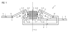
- FIG. 1 shows an example of a switching device 1 according to the invention according to a first embodiment in a side view.
- two switching contact pairs designated by the reference symbols 2, 3 are provided for interrupting a current path 4.
- the current i to be interrupted by the inventive switching device 1 flows in the FIG. 1 left to right.
- the switching contact pairs 2, 3 each have a movable switching contacts 21, 31 and in each case a fixed contact 22, 32.
- the switching contact pairs 2, 3 are connected in series in such a way that the same current i flowing in the two arcs 6 flows spatially in the same direction.
- the current direction is symbolized by an arrow approximately in the middle of the two arcs 6.
- This is achieved for the present embodiment in that exactly one of the movable switching contacts 31 is electrically connected to the fixed contact 22 of the other switching contact pair 2.
- the remaining switching contacts 21, 32 are each connected to the current path 4 via a connecting conductor 8.
- the current i coming from the left flows over the left partial arc 61 of the first switching contact pair 2 from top to bottom. It continues to flow via the connecting conductor 8 to the movable switching contact 31 of the right switching contact pair 3 to continue from there via the right part of the arc 62 from top to bottom to the right flow path 4 on.
- the current directions are reversed when the current i would flow from right to left into the switching device 1.
- the same current i flowing in both arcs 6 flows spatially in the same direction, ie from bottom to top.
- the deletion package 5 between the two opening paths 7, that is, between the free ends of the switching contacts 21, 22, 31, 32, respectively.
- the opening tracks 7 are characterized by an arrow opposite the direction of the flow.
- the opening of the switching contact pairs 2, 3 takes place in accordance with the illustration shown from bottom to top.
- the two movable switching contacts 21, 31 are each pivotally mounted about a pivot point 10. The two free ends of the switching contacts 21, 31, that is in particular the switching contact pieces 11 of the two switching contacts 21, 31, adjoin the extinguishing package 5.
- the Lorentz force F is the cross product of the current i as well as of the magnetic field, ie the magnetic induction B1, B2.
- the current i flows perpendicular to the magnetic field B1, which is generated by the right current i in the partial arc 62. Due to the Lorentz force F, the left partial arc 61 is pressed into the extinguishing package 5, so to speak.
- the magnetic field B2 is shown, which is generated by the left current i in the left partial arc 61.
- the reference symbol E denotes a sectional plane perpendicular to the image plane of the FIG. 1 runs and to which the switching contact pairs 2, 3 are arranged symmetrically.
- the reference character L designates the longitudinal extension or symmetry axis of the deletion package 5.
- a partition wall is referred to, which electrically separates the two arcs 6 from each other.
- the not further designated plates of the extinguishing package 5 itself are exemplified of an electrically non-conductive plastic, such as made of a thermoplastic.
- PBT polybutylene terephthalate
- POM polyoxymethylene
- the extinguishing package 5 can moreover be made of a magnetic material, in particular of a ferromagnetic material.
- the two arcs 6 are further pressed by the magnetic amplification in the deletion package 5 shown.
- An electrically non-conductive plastic and at the same time magnetically conductive plastic can e.g. be a previously described thermoplastic, in whose matrix ferromagnetic particles, such as metallic iron, cobalt, nickel particles or alloys thereof are introduced.
- Such a plastic preferably has a magnetic permeability of more than 10.
- the plastic may also be an electrically conductive plastic, if a corresponding electrically non-conductive partition wall 9 is inserted in the extinguishing package 5 in order to electrically separate the two switching contact pairs 2, 3 from each other.
- Conductive plastics can e.g. by the addition of electrically conductive substances, such as metals, carbon black or graphite, or by suitable doping of electrically non-conductive polymers.
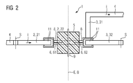
- FIG. 2 shows the switching device 1 according to FIG. 1 in a top view.
- the connecting conductor 8 is guided around the extinguishing package 5 and around the switching contact pair 3 in order to effect a corresponding current flow in the opposite direction.
- the reference character Q denotes a transverse symmetry axis of the erase packet 5.
- the pivot axes of the pivotally designed switching contacts 21, 31 are designated.
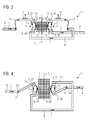
- FIG. 3 shows a second embodiment of the switching device 1 according to the invention in a side view.
- the movable switching contacts 21, 31 move linearly from the fixed contacts 22, 32 along the registered opening path 7 away from bottom to top. The movement takes place in the example of FIG. 3 in each case via an actuator designated by the reference numeral 12.
- the two actuators 12 are preferably summarized to an actuator 12.
- the two movable switching contacts 21, 31 are electrically connected via a movable strand to the current path 4 and to the connecting conductor 8, respectively.
- FIG. 4 shows a third embodiment of the switching device 1 according to the invention in a side view.
- the free ends of the two movable switching contacts 21, 32 ' are formed such that they move away from each other when opening.
- the illustrated left switch contact 21 moves from bottom to top.
- the right movable switch contact 32 ' moves from top to bottom.
- the two arcs 6 are driven by the acting Lorentz force F in the extinguishing package 5.
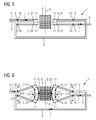
- FIG. 5 shows a fourth embodiment of the switching device 1 according to the invention in a side view with closed switching contacts 21, 22 ', 31, 32'.
- the latter are each arranged pivotably about a pivot point 10.
- the contact pieces 11 of the switching contact pairs 2, 3 lie in a ground plane G, which is arranged perpendicular to the sectional plane E.
- the switching contact pairs 2, 3 shown are preferably arranged in mirror image to both planes G, E.
- the free ends of the switching contacts 21, 22 ', 31, 32' in turn adjoin the extinguishing package 5.
- FIG. 6 shows the switching device 1 according to FIG. 5 with opening switching contacts 21, 22 ', 31, 32', which move away from each other. It is one of the movable switching contacts 22 'electrically connected to the respective movable switching contact 31 of the other switching contact pair 2, which moves when opening substantially in the opposite direction.
- the current i flows again in the same spatial direction, that is, from top to bottom.
- the current i flow in the two arcs 6 spatially in the same direction, regardless of whether the current i flows over the current paths 4 from left to right or vice versa from right to left.
- the switching device 1 according to the invention is thus suitable for interrupting direct currents as well as alternating currents.
Applications Claiming Priority (1)
| Application Number | Priority Date | Filing Date | Title |
|---|---|---|---|
| DE102008005115A DE102008005115A1 (de) | 2008-01-14 | 2008-01-14 | Schaltgerät, insbesondere Leistungsschaltgerät, mit zwei in Reihe, geschalteten Schaltkontaktpaaren zur Unterbrechung einer Strombahn |
Publications (2)
| Publication Number | Publication Date |
|---|---|
| EP2079088A2 true EP2079088A2 (fr) | 2009-07-15 |
| EP2079088A3 EP2079088A3 (fr) | 2010-08-18 |
Family
ID=40364504
Family Applications (1)
| Application Number | Title | Priority Date | Filing Date |
|---|---|---|---|
| EP09150080A Withdrawn EP2079088A3 (fr) | 2008-01-14 | 2009-01-06 | Commutateur, notamment commutateur de puissance doté de deux paires de contacts commutés en série pour interrompre une voie de courant |
Country Status (4)
| Country | Link |
|---|---|
| US (1) | US7902948B2 (fr) |
| EP (1) | EP2079088A3 (fr) |
| CN (1) | CN101488403B (fr) |
| DE (1) | DE102008005115A1 (fr) |
Cited By (1)
| Publication number | Priority date | Publication date | Assignee | Title |
|---|---|---|---|---|
| EP2393094A1 (fr) * | 2010-06-07 | 2011-12-07 | Eaton Industries GmbH | Unité de commutation dotée d'unités d'extinction d'arc |
Families Citing this family (14)
| Publication number | Priority date | Publication date | Assignee | Title |
|---|---|---|---|---|
| US8525526B2 (en) * | 2009-11-13 | 2013-09-03 | Hubbell Incorporated | High voltage test terminal having a shock-absorbing insulator |
| JP5134657B2 (ja) * | 2010-07-27 | 2013-01-30 | 富士電機機器制御株式会社 | 接点機構及びこれを使用した電磁接触器 |
| EP2425746B1 (fr) * | 2010-09-03 | 2018-01-24 | Electrolux Home Products Corporation N.V. | Appareil domestique avec socle ajustable |
| JP5838920B2 (ja) * | 2011-07-18 | 2016-01-06 | アンデン株式会社 | 継電器 |
| JP5585550B2 (ja) * | 2011-07-18 | 2014-09-10 | アンデン株式会社 | 継電器 |
| EP2631928A1 (fr) * | 2011-11-29 | 2013-08-28 | Eaton Industries GmbH | Système d'aimant permanent pour un circuit d'attaque à arc lumineux et appareil de commutation |
| CN102903576B (zh) * | 2012-10-27 | 2015-06-03 | 东莞市三友联众电器有限公司 | 磁保持继电器的簧片开关组件 |
| EP2782110B1 (fr) * | 2013-03-22 | 2017-07-05 | Tyco Electronics Austria GmbH | Dispositif de commutation électrique activé par force de Lorentz |
| EP2806441B1 (fr) * | 2013-05-24 | 2017-07-12 | Tyco Electronics Austria GmbH | Dispositif de commutation électrique avec une force de Lorentz améliorée |
| US9412549B2 (en) | 2014-02-18 | 2016-08-09 | General Electric Company | Electromagnetically enhanced contact separation in a circuit breaker |
| EP3146548B1 (fr) * | 2014-05-19 | 2018-12-05 | ABB Schweiz AG | Dispositif d'appareillage électrique de coupure limiteur ultrarapide |
| EP3101678B1 (fr) * | 2015-06-01 | 2017-09-13 | Wöhner GmbH & Co. KG Elektrotechnische Systeme | Disjoncteur |
| EP3557599B1 (fr) * | 2018-04-19 | 2024-01-10 | ABB S.p.A. | Disjoncteur basse tension |
| KR20200095210A (ko) | 2019-01-31 | 2020-08-10 | 엘지전자 주식회사 | 반도체 발광 소자, 이의 제조 방법, 및 이를 포함하는 디스플레이 장치 |
Citations (3)
| Publication number | Priority date | Publication date | Assignee | Title |
|---|---|---|---|---|
| EP0174904A1 (fr) * | 1984-08-23 | 1986-03-19 | Siemens Aktiengesellschaft | Dispositif de contact pour disjoncteur basse tension avec un levier de contact à deux bras |
| DE19629867A1 (de) * | 1996-07-24 | 1998-02-05 | Kloeckner Moeller Gmbh | Strombegrenzender Leistungsschalter |
| DE112007003283T5 (de) * | 2007-01-24 | 2010-02-04 | Siemens Aktiengesellschaft | Doppelunterbrechungskontaktsystem für einen Niederspannungsleistungsschalter und das Doppelunterbrechungskontaktsystem umfassender Kompaktleistungsschalter |
Family Cites Families (12)
| Publication number | Priority date | Publication date | Assignee | Title |
|---|---|---|---|---|
| GB236293A (en) * | 1924-04-05 | 1925-07-06 | Edmund Basil Wedmore | Improvements in or relating to electric circuit breakers |
| US3068379A (en) * | 1957-04-11 | 1962-12-11 | Fed Pacific Electric Co | Circuit protective apparatus |
| US3593227A (en) * | 1968-02-28 | 1971-07-13 | Gennady Fedosievich Mitskevich | Automatic electrodynamic blowoff breaker with stationary contact form of two series wound u-shaped members |
| US3959753A (en) * | 1974-01-25 | 1976-05-25 | Westinghouse Electric Corporation | Circuit interrupter with load side short circuit |
| US4656446A (en) * | 1985-12-17 | 1987-04-07 | Westinghouse Electric Corp. | Current limiting circuit breaker with series double break contact system per pole |
| DE3810977C2 (de) * | 1988-03-28 | 1996-10-24 | Siemens Ag | Strombegrenzende Schalteinrichtung mit elektrodynamisch öffnenden Schaltstücken |
| JPH088048B2 (ja) * | 1989-09-18 | 1996-01-29 | 三菱電機株式会社 | 限流装置 |
| DE19517634C2 (de) * | 1995-05-13 | 2002-01-31 | Abb Patent Gmbh | Elektrisches Installationsschaltgerät |
| US6232570B1 (en) * | 1999-09-16 | 2001-05-15 | General Electric Company | Arcing contact arrangement |
| US6184761B1 (en) * | 1999-12-20 | 2001-02-06 | General Electric Company | Circuit breaker rotary contact arrangement |
| US6534737B1 (en) * | 2002-02-19 | 2003-03-18 | Onan Corporation | Contact closing speed limiter for a transfer switch |
| JP2007280928A (ja) * | 2006-03-13 | 2007-10-25 | Fuji Electric Fa Components & Systems Co Ltd | 回路遮断器 |
-
2008
- 2008-01-14 DE DE102008005115A patent/DE102008005115A1/de not_active Withdrawn
-
2009
- 2009-01-06 EP EP09150080A patent/EP2079088A3/fr not_active Withdrawn
- 2009-01-13 US US12/319,859 patent/US7902948B2/en not_active Expired - Fee Related
- 2009-01-13 CN CN2009100001639A patent/CN101488403B/zh not_active Expired - Fee Related
Patent Citations (3)
| Publication number | Priority date | Publication date | Assignee | Title |
|---|---|---|---|---|
| EP0174904A1 (fr) * | 1984-08-23 | 1986-03-19 | Siemens Aktiengesellschaft | Dispositif de contact pour disjoncteur basse tension avec un levier de contact à deux bras |
| DE19629867A1 (de) * | 1996-07-24 | 1998-02-05 | Kloeckner Moeller Gmbh | Strombegrenzender Leistungsschalter |
| DE112007003283T5 (de) * | 2007-01-24 | 2010-02-04 | Siemens Aktiengesellschaft | Doppelunterbrechungskontaktsystem für einen Niederspannungsleistungsschalter und das Doppelunterbrechungskontaktsystem umfassender Kompaktleistungsschalter |
Cited By (3)
| Publication number | Priority date | Publication date | Assignee | Title |
|---|---|---|---|---|
| EP2393094A1 (fr) * | 2010-06-07 | 2011-12-07 | Eaton Industries GmbH | Unité de commutation dotée d'unités d'extinction d'arc |
| WO2011154380A1 (fr) * | 2010-06-07 | 2011-12-15 | Eaton Industries Gmbh | Unité de commutation munie d'unités d'extinction d'arc |
| US8921728B2 (en) | 2010-06-07 | 2014-12-30 | Eaton Electrical Ip Gmbh & Co. Kg | Switch unit with arc-extinguishing units |
Also Published As
| Publication number | Publication date |
|---|---|
| CN101488403B (zh) | 2011-06-15 |
| CN101488403A (zh) | 2009-07-22 |
| DE102008005115A1 (de) | 2009-07-16 |
| EP2079088A3 (fr) | 2010-08-18 |
| US20090179009A1 (en) | 2009-07-16 |
| US7902948B2 (en) | 2011-03-08 |
Similar Documents
| Publication | Publication Date | Title |
|---|---|---|
| EP2079088A2 (fr) | Commutateur, notamment commutateur de puissance doté de deux paires de contacts commutés en série pour interrompre une voie de courant | |
| EP2649630B1 (fr) | Interrupteur à chambre d'extinction | |
| EP2649628B1 (fr) | Interrupteur à chambre d'extinction | |
| EP3048626B1 (fr) | Appareil de commutation avec soufflage d'arc par aimant permanent | |
| EP2786385B1 (fr) | Appareil de commutation pour applications à courant continu | |
| EP2463878A1 (fr) | Commutateur doté d'une chambre d'extinction | |
| AT509277A1 (de) | Schaltgerät | |
| EP1683173B1 (fr) | Dispositif d'extinction d'arc | |
| WO2013064629A1 (fr) | Commutateur pour fonctionnement en courant continu multipolaire | |
| DE4332546A1 (de) | Niederspannungsschalter in isolierendem Gehäuse | |
| DE102018204104A1 (de) | Schalteinheit zur Trennung eines Stromkreises und Schutzschalter | |
| WO2012076605A1 (fr) | Interrupteur à chambre d'extinction | |
| EP2795643B1 (fr) | Disjonteur à courant continu | |
| EP1548773A1 (fr) | Chambre de soufflage pour un disjoncteur-protecteur possédant une double coupure | |
| DE1640262B2 (de) | Strombegrenzungsschalter | |
| DE102006028696A1 (de) | Leistungsschalter oder Leitungsschutzschalter | |
| EP3084794B1 (fr) | Dispositif de commutation | |
| EP2541574B1 (fr) | Disjoncteur électrique à double point de rupture | |
| EP2631928A1 (fr) | Système d'aimant permanent pour un circuit d'attaque à arc lumineux et appareil de commutation | |
| EP3291266B1 (fr) | Unité de circuit pour un commutateur électrique et commutateur électrique | |
| EP3084798A1 (fr) | Appareil de coupure | |
| WO2014068054A1 (fr) | Dispositif de commutation à courant continu | |
| WO2015177137A1 (fr) | Appareil de coupure électrique |
Legal Events
| Date | Code | Title | Description |
|---|---|---|---|
| PUAI | Public reference made under article 153(3) epc to a published international application that has entered the european phase |
Free format text: ORIGINAL CODE: 0009012 |
|
| AK | Designated contracting states |
Kind code of ref document: A2 Designated state(s): AT BE BG CH CY CZ DE DK EE ES FI FR GB GR HR HU IE IS IT LI LT LU LV MC MK MT NL NO PL PT RO SE SI SK TR |
|
| AX | Request for extension of the european patent |
Extension state: AL BA RS |
|
| PUAL | Search report despatched |
Free format text: ORIGINAL CODE: 0009013 |
|
| AK | Designated contracting states |
Kind code of ref document: A3 Designated state(s): AT BE BG CH CY CZ DE DK EE ES FI FR GB GR HR HU IE IS IT LI LT LU LV MC MK MT NL NO PL PT RO SE SI SK TR |
|
| AX | Request for extension of the european patent |
Extension state: AL BA RS |
|
| RIC1 | Information provided on ipc code assigned before grant |
Ipc: H01H 77/10 20060101ALI20100713BHEP Ipc: H01H 73/04 20060101ALI20100713BHEP Ipc: H01H 9/34 20060101AFI20090227BHEP |
|
| 17P | Request for examination filed |
Effective date: 20100921 |
|
| AKX | Designation fees paid |
Designated state(s): AT BE BG CH CY CZ DE DK EE ES FI FR GB GR HR HU IE IS IT LI LT LU LV MC MK MT NL NO PL PT RO SE SI SK TR |
|
| STAA | Information on the status of an ep patent application or granted ep patent |
Free format text: STATUS: THE APPLICATION IS DEEMED TO BE WITHDRAWN |
|
| 18D | Application deemed to be withdrawn |
Effective date: 20120801 |