EP2806441B1 - Dispositif de commutation électrique avec une force de Lorentz améliorée - Google Patents
Dispositif de commutation électrique avec une force de Lorentz améliorée Download PDFInfo
- Publication number
- EP2806441B1 EP2806441B1 EP13169164.4A EP13169164A EP2806441B1 EP 2806441 B1 EP2806441 B1 EP 2806441B1 EP 13169164 A EP13169164 A EP 13169164A EP 2806441 B1 EP2806441 B1 EP 2806441B1
- Authority
- EP
- European Patent Office
- Prior art keywords
- lorentz force
- conductor
- force generator
- contact
- members
- Prior art date
- Legal status (The legal status is an assumption and is not a legal conclusion. Google has not performed a legal analysis and makes no representation as to the accuracy of the status listed.)
- Not-in-force
Links
- 239000004020 conductor Substances 0.000 claims description 245
- 230000004888 barrier function Effects 0.000 description 10
- 238000002955 isolation Methods 0.000 description 10
- 239000006227 byproduct Substances 0.000 description 9
- 238000003825 pressing Methods 0.000 description 3
- 238000000926 separation method Methods 0.000 description 3
- 238000010276 construction Methods 0.000 description 2
- 230000000694 effects Effects 0.000 description 2
- 238000004519 manufacturing process Methods 0.000 description 2
- 229910001316 Ag alloy Inorganic materials 0.000 description 1
- BQCADISMDOOEFD-UHFFFAOYSA-N Silver Chemical compound [Ag] BQCADISMDOOEFD-UHFFFAOYSA-N 0.000 description 1
- 238000005299 abrasion Methods 0.000 description 1
- 230000003321 amplification Effects 0.000 description 1
- 238000005452 bending Methods 0.000 description 1
- 230000005540 biological transmission Effects 0.000 description 1
- 230000001627 detrimental effect Effects 0.000 description 1
- 230000005489 elastic deformation Effects 0.000 description 1
- 230000002401 inhibitory effect Effects 0.000 description 1
- 239000000463 material Substances 0.000 description 1
- 229910052751 metal Inorganic materials 0.000 description 1
- 239000002184 metal Substances 0.000 description 1
- 238000003199 nucleic acid amplification method Methods 0.000 description 1
- 238000013341 scale-up Methods 0.000 description 1
- 229910052709 silver Inorganic materials 0.000 description 1
- 239000004332 silver Substances 0.000 description 1
- 238000003466 welding Methods 0.000 description 1
Images


Classifications
-
- H—ELECTRICITY
- H01—ELECTRIC ELEMENTS
- H01H—ELECTRIC SWITCHES; RELAYS; SELECTORS; EMERGENCY PROTECTIVE DEVICES
- H01H1/00—Contacts
- H01H1/50—Means for increasing contact pressure, preventing vibration of contacts, holding contacts together after engagement, or biasing contacts to the open position
- H01H1/54—Means for increasing contact pressure, preventing vibration of contacts, holding contacts together after engagement, or biasing contacts to the open position by magnetic force
-
- H—ELECTRICITY
- H01—ELECTRIC ELEMENTS
- H01H—ELECTRIC SWITCHES; RELAYS; SELECTORS; EMERGENCY PROTECTIVE DEVICES
- H01H50/00—Details of electromagnetic relays
- H01H50/16—Magnetic circuit arrangements
- H01H50/18—Movable parts of magnetic circuits, e.g. armature
-
- H—ELECTRICITY
- H01—ELECTRIC ELEMENTS
- H01H—ELECTRIC SWITCHES; RELAYS; SELECTORS; EMERGENCY PROTECTIVE DEVICES
- H01H50/00—Details of electromagnetic relays
- H01H50/16—Magnetic circuit arrangements
- H01H50/36—Stationary parts of magnetic circuit, e.g. yoke
-
- H—ELECTRICITY
- H01—ELECTRIC ELEMENTS
- H01H—ELECTRIC SWITCHES; RELAYS; SELECTORS; EMERGENCY PROTECTIVE DEVICES
- H01H50/00—Details of electromagnetic relays
- H01H50/54—Contact arrangements
-
- H—ELECTRICITY
- H01—ELECTRIC ELEMENTS
- H01H—ELECTRIC SWITCHES; RELAYS; SELECTORS; EMERGENCY PROTECTIVE DEVICES
- H01H50/00—Details of electromagnetic relays
- H01H50/54—Contact arrangements
- H01H50/60—Contact arrangements moving contact being rigidly combined with movable part of magnetic circuit
Definitions
- the invention relates to an electric switching device, such as a relay, comprising a first and a second terminal, a contact sub-assembly having at least two contact members and configured to be moved from a connecting position, in which the contact members contact each other, to an interruption position, in which the contact members are spaced apart from each other, a current path extending, in the connection position of the contact sub-assembly, from the first terminal via the contact sub-assembly to the second terminal, said current path being interrupted in the interruption position of the contact sub-assembly, and a Lorentz force generator comprising at least two conductor members located in the current path and arranged to generate the Lorentz force acting on the conductor members and generating a contact force biasing the contact sub-assembly into the connecting position.
- a Lorentz force generator comprising at least two conductor members located in the current path and arranged to generate the Lorentz force acting on the conductor members and generating a contact force biasing the contact sub-a
- Such electric switching devices are generally known from the prior art. If the contact members are in the connecting position, the current path extends continuously through the electric switching device and a current is flowing through the electric switching device along the current path. If the contact members are moved apart, the current path and thus the current flowing through the electric switching device is disrupted.
- Electric switching devices in particular relays, are mass-produced articles which need to be of simple structure and inexpensive to manufacture. Moreover, the switching action should be reliable over many cycles.
- an electromagnetic repulsive force arises between the contact members of the contact sub-assembly because currents flow in the opposite directions in portions where the contact members contact each other in the connecting position.
- the electromagnetic repulsive force acts to separate the contact members from each other.
- the contact sub-assembly is biased into the connecting position by, e.g. pressure springs or a Lorentz force.
- the electromagnetic repulsive force increases as the flowing current increases. Therefore, the elastic force of a biasing spring or the Lorentz force has to be increased in accordance with the increase in the current value. As a result, the body size of the contact spring or the length of the conductor members of the Lorentz force generator enlarges. This requires, in turn, to scale up the size of the electric switching device.
- US 6,034,581 relates to an electric switching device according to the preamble of claim 1. It discloses a contact assembly which is adapted for use with a circuit breaker that is set to open a circuit above a predetermined current load.
- the contact assembly is adapted to reciprocate between a closed position to permit the flow of current through the circuit and an open position to prevent the flow of current.
- the contact assembly is further adapted to resist unintended reciprocation from the closed position to the open position at current loads up to or exceeding the predetermined current load.
- the contact assembly includes a line side conductor and a load side conductor.
- a surface of the line side conductor When in the closed position, a surface of the line side conductor extends proximal to a surface of the load side conductor and current flows in substantially the same direction along the line side and load side surfaces to generate an electromagnetic attraction between the conductors in order to resist unintended reciprocation of the contact assembly from the closed position to the open position due to inherent repulsion forces present across the contact points (contact constriction forces).
- a circuit breaker assembly and an automated control system are also described.
- WO 93/23863 refers to a contact spring arrangement which has an elongated contact spring with a rigid connection leg which extends approximately parallel to the contact spring and which conducts the switching current in a direction opposite to the contact spring.
- the contact spring On the side opposite to the connection leg, the contact spring has a contact piece which co-operates with an opposite counter-contact element provided with a contact piece. The repulsion forces between the connection leg and the contact spring are thus so increased that no welding of the contacts occurs, even at the highest short circuit currents, provided that the width of the gap between the contact spring and the connection leg be at least 20 times larger than the average spring spacing in the gap, when the contact pieces are made of silver or a silver alloy.
- the present invention strives to address these issues and aims to provide an electric switching device, such as relay, which can be produced cost-efficiently, has a simple structure, is reliable and yet inhibits the accidental separation of the contact members of the contact sub-assembly due to an electromagnetic repulsive force even at high current values.
- the electric switching device further comprises at least one support Lorentz force generator arranged to generate an enforcing Lorentz force amplifying the contact force biasing the contact sub-assembly into the connecting position.
- the electric switching device further comprises a joint conductor member, said joint conductor member being a conductor member of the Lorentz force generator and also being a conductor member of the support Lorentz force generator. This way, the Lorentz force generator and at least one support Lorentz force generator share one conductor member, allowing for a configuration in which, e.g. a design with three conductor members constitutes one Lorentz force generator and one support Lorentz force generator.
- the joint conductor member is arranged adjacent to a conductor member of the Lorentz force generator, and the conductor member of the at least one support Lorentz force generator is arranged adjacent to said conductor member of the Lorentz force generator opposite to the joint conductor member.
- the conductor members of the Lorentz force generator and the at least one support Lorentz force generator are arranged on the same side of the joint conductor member, said same side being with respect to a plane defined by the Lorentz force acting on the joint conductor member.
- the electric switching device does not increase the existing biasing component, e.g. the size of a spring or a Lorentz force. Rather, the electric switching device of the invention comprises at least one further Lorentz force generator, a support Lorentz force generator which generates an additional supplementary Lorentz force, hereafter called enforcing Lorentz force.
- the enforcing Lorentz force of the support Lorentz force generator and the Lorentz force of the Lorentz force generator sum up and thus amplify the contact force biasing the contact sub-assembly in the connecting position. This amplification allows the electric switching device of the invention to sustain much higher current values flowing therethrough without an accidental electromagnetic repulsion of the contact members of the contact sub-assembly.
- an electric switching device with a support Lorentz force generator enables an electric switching device to be designed with a simple structure which is inexpensive to manufacture.
- the electric switching device according to the invention is reliable over many switching cycles because the generation of a Lorentz force does not lead to mechanic abrasion or other wear at the conductor members.
- the size of the support Lorentz force generator can be easily matched to the size of the Lorentz force generator, in particular the length of the conductor members thereof, so there is no need to increase the length of the conductor members of the Lorentz generator in order to increase the Lorentz force in the electric switching device of the invention.
- the at least one support Lorentz force generator may comprise at least two conductor members located in the current path and arranged to the enforcing Lorentz force acting on the conductor members. This allows for a simple yet effective design of the support Lorentz force generator.
- the Lorentz force and/or the enforcing Lorentz force may be applied immediately on at least one of the contact members, e.g. by pressing them against each other.
- the Lorentz force and/or the enforcing Lorentz force may also be indirectly applied in that at least one translation element, such as a mechanical element, is interposed operatively between the conductor members, on which the generated Lorentz force/enforcing Lorentz force acts, and the contact sub-assembly.
- the translation element receives the Lorentz forces acting on the conductor members, and in turn generating the contact force biasing the contact sub-assembly into the connecting position.
- the path of the Lorentz force is then extended via the transmission element to the contact sub-assembly.
- the Lorentz force generator is preferably arranged in series to the contact sub-assembly, i.e. either in front of or behind the contact sub-assembly in the current path.
- the at least one support Lorentz force generator is also preferably arranged in series to the contact sub-assembly, either in front of or behind the contact sub-assembly (and/or the Lorentz force generator or another support Lorentz force generator) in the current path.
- At least one of the conductor members is configured to be deflected by the Lorentz force and/or the support Lorentz force relative to the currentless state.
- the deflection may be used as the driving motion which generates the contact force biasing the contact sub-assembly into the connecting position.
- the deflectable conductor may be provided with an affixed end and a moveable end opposite the fixed end. Such a lever-like configuration can increase the Lorentz force and allows for an effective biasing of the contact sub-assembly into the connecting position.
- the moveable end of the preferably deflectable conductor member may be provided with at least one contact member, which contact member may be directly driven by the Lorentz force, thereby achieving a simple and reliable yet effective and compact structure.
- At least one conductor member of the Lorentz force generator and/or the support Lorentz force generator may be more rigid than a deflectable contact member.
- the more rigid contact members may be regarded as a rigid body over the operational range of currents of the Lorentz force generator and the at least one support Lorentz force generator, which rigid body does not substantially deform under the Lorentz forces acting thereon.
- the electric switching device may comprise an isolation barrier, which isolates adjacent conductors from each other and assures that the deformation of the contact members of the Lorentz force generator and of the at least one support Lorentz force generator is kept to a degree that does not negatively effect the functioning of the electric switching device.
- the barrier may be a non-conductive structure, such as a pin, wall or other support or boundary inhibiting an undesired deformation of a conductor member.
- the various components of the current path need to have a large cross-section to safely conduct the current.
- the high cross-sectional area needed for the large currents may be detrimental to the flexibility thereof.
- the deflectable conductor member needs to have a certain flexibility.
- the deflectable conductor member comprises a mid-section end sections bordering the mid-section and where the deflectability of the deflectable conductor members is higher in the mid-section than in the end sections. The increased deflectability in the mid-section will lead to an easier deformation of the conductor member in this area and thus to a large stroke generated by the Lorentz force generator and/or the at least one supporting Lorentz force generator.
- a multi-layered deflectable conductor member that comprises several layers of the conductive sheet metal may be used.
- the layers may, at least partially, be non-parallel to each other in the mid-section to increase deflectability there.
- at least one of the layers may be bent at the mid-section.
- the at least two conductor members of the Lorentz force generator may be fixed to one another, preferably at at least one of their ends.
- the affixation of the at least two connector elements to one another is an easy way of connecting them electrically.
- the affixation should allow the Lorentz force to be taped, e.g. by allowing a deflection of at least one of the conductor members.
- the at least two conductor members of the Lorentz force generator and/or the at least one support Lorentz force generator, preferably of all conductor members of the Lorentz force generator and of all the support Lorentz force generators may be connected in series to obtain a simple configuration of the switching device.
- the at least two conductor members of the Lorentz force generator and/or the at least one support Lorentz force generator extend parallel to each other.
- At least one conductor member of the Lorentz force generator and at least one conductor of the support Lorentz force generator may extend parallel to each other and, in a further embodiment, all conductor members of the Lorentz force generator and all conductor members of the support Lorentz force generators extend parallel to each other, which allows for a very compact design and may reduce the total number of conductor members.
- the joint conductor member is a deflectable conductor member.
- Such joint, deflectable conductor member may be, in an arbitrary combination, attracted to or repelled from the other conductor member, with which it builds a Lorentz force generator/support Lorentz force generator.
- the at least two conductor members of the Lorentz force generator and/or the at least one support Lorentz force generator may extend adjacent to one another, thereby minimizing the distance in between and thus increasing the Lorentz force generated.
- the conductor members may not only extend adjacent to one another, but also extend parallel, i.e. they may be arranged adjacent and parallel to each other.
- the contact force biasing the contact sub-assembly into the connecting position may be efficiently amplified reliably at low costs and with a simple structure.
- Figs. 1 and 2 the configuration of the switching device according to the first embodiment of the invention is explained with reference to Figs. 1 and 2 .
- Fig. 2 some of the reference signs of Fig. 1 have been omitted for clarity.
- the schematic representation of the electric switching device is reduced in (all of) the figures only to the components constituting the current path of the electric switching device,
- the electric switching device 1 comprises a first terminal 2 and a second terminal 4, which may be electrically connected to machinery or circuitry (both not shown).
- the electric switching device 1 further comprises a contact sub-assembly 6, which includes at least two contact members 8, 10.
- the contact sub-assembly 6 may be moved from an interrupting position 14 shown in Fig. 1 , in which the contact members 8, 10 are spaced apart from each other, to a connecting position 12 shown in Fig. 2 .
- the contact members 8, 10 contact each other.
- a current path 16 indicated by the small arrows in the figures, extends between the first and the second terminals 2, 4.
- an electric current may flow between the first terminal 2 and the second terminal 4 along the current path 16.
- the current path is interrupted at the contact sub-assembly 6, whose contact members 8, 10 are spaced apart from each other, and no current may flow between the terminals 2, 4.
- the electric switching device 1 further comprises a Lorentz force generator 18, which may be located in series to the contact sub-assembly 6. It may be located in the current path 16 in front of or behind the contact sub-assembly 6. In the embodiment shown in Figs. 1 and 2 , the Lorentz force generator 18 is located in the current path 16 in front of the contact sub-assembly 6.
- the Lorentz force generator 18 which comprises at least two conductor members 20, 22, generates a Lorentz force 24.
- the conductor members 20, 22 are preferably located in the current path 16. If an electric current path is applied along the current path 16, the Lorentz force 24 is generated, which acts between the conductor members 20, 22.
- the direction of a Lorentz force 24 depends on the direction of the current in the conductor members 20, 22. If the current is of the same direction in the conductor members 20, 22, the Lorentz force 24 will act to attract the conductor members 20, 22 to each other.
- the direction of the current in the conductor member 20 is opposite to the direction of the current in the conductor member 22.
- the Lorentz force 24 will push the conductor members 20, 22 apart. This immediate effect of the Lorentz force 24 results in a contact force 25 pressing the contact members 8, 10 into contact with each other.
- At least one of the conductor members 20, 22 may be configured to be deflected by the Lorentz force 24 relative to an initial currentless state, which may be the interrupting position 14 shown in Fig. 1 .
- an initial currentless state which may be the interrupting position 14 shown in Fig. 1 .
- the deflectable conductor member 20 is fixed at one end 26, while the other end 28 is moveable.
- the deflection of the conductor member 20 may in particular be an elastic deformation. If the conductor member 20 is in the deflected state, the moveable end 28, which may be provided with a contact member 10 of the contact sub-assembly 6, is pressed against the contact member 8 of the contact sub-assembly 6, thereby biasing the contact sub-assembly 6 into the connecting position 12 shown in Fig. 2 .
- the contact member 8 is fixed in position, i.e. non-moveable.
- the at least two conductor members 20, 22 of the Lorentz force generator 18 preferably extend parallel and adjacent to each other, as shown in Figs. 1 and 2 . This ensures that the Lorentz force 24 is generated with maximum efficiency.
- the conductor members 20, 22 are fixed to each other at the fixed end 26 of the conductor member 20, the conductor members 20, 22 may be connected in series within the current path 16.
- the electromagnetic repulsive force 30 While the maximum Lorentz force 24 that the Lorentz force generator 18 is capable of generating is limited, for example by the distance between the conductor members 20, 22 and the length of the two conductor members 20, 22, the electromagnetic repulsive force 30 continues to rise with increasing currents flowing through the current path 16. At very high currents flowing through the current path 16, the electromagnetic repulsive force 30, acting to separate the contact members 8, 10 from each other, may exceed the Lorentz force 24 of the Lorentz force generator 18, pressing the contact members 8, 10 against each other and thus biasing the contact sub-assembly 6 into the connecting position.
- the contact force 25 biasing the contact sub-assembly 6 into the connecting position 12 generated by the Lorentz force generator 18 is amplified by means of at least one support Lorentz force generator 32 as explained in the following by reference to the exemplary first embodiment of the electric switching device 1 according to the invention shown in Figs. 1 and 2 .
- the support Lorentz force generator 32 comprises at least two conductor members 20, 34.
- the conductor members 20, 34 are located in the current path 16. If a current is applied along the current path 16, a further Lorentz force, called an enforcing Lorentz force 36, is generated which acts between the conductor members 20, 34. In the embodiment shown, the direction of the current in the conductor member 20 is opposite to the direction of the current in the conductor member 34. Thus, the enforcing Lorentz force 36 will also push the contact member 10 against the contact member 8, thus generating a second component of the contact force 25 and amplifying the contact force 25 biasing the contact sub-assembly 6 into the connecting position 12.
- the deflector conductor member 20 is a joint conductor member 38, which is a conductor member 20 of the Lorentz force generator 18 and also a conductor member 20 of the at least one support Lorentz force generator 32.
- the total number of conductor members in the Lorentz force generator 18 and the support Lorentz force generator 32 can be reduced, which makes the construction of the electric switching device 1 of the invention easier. Further, it reduces the conductor material needed, and thus the costs for an electric switching device 1.
- the conductor members 20, 22 of the Lorentz force generator 18 are connected in series.
- the conductor members 20, 34 of the support Lorentz force generator 32 are also connected in series.
- the serial connection from the first terminal 2 to the second terminal 4 which constitutes the current path 16, in the following order: first terminal 2, conductor member 22, flexible conductor member 20, contact sub-assembly 6 with contact members 8, 10, a crossover conductor 40, conductor member 34 and finally second terminal 4.
- the conductor members 20, 22 of the Lorentz force generator 18 extend parallel to each other, which maximizes the Lorentz force 24 generated.
- the at least two conductor members 20, 34 of the support Lorentz force generator 32 also extend parallel to each other, which maximizes the enforcing Lorentz force 36, thereby maximizing the contact force 25 which is the result of the combined Lorentz force 24 and enforcing Lorentz force 36 acting in the same direction on the deflectable conductor member 20.
- the one conductor member 22 of the Lorentz force generator 18 and the conductor member 34 of the support Lorentz force generator 32 may also extend parallel to each other, which minimizes the spatial requirements for placing the conductor members and allows for a compact construction of the electric switching device 1.
- all conductor members 20, 22 of the Lorentz force generator 18 and all conductor members 20, 34 of the at least one support Lorentz force generator 32 extend parallel to each other.
- the generated Lorentz force 24, 36 may be increased by placing the conductor members 20, 22/20, 34 extending adjacent to each other, preferably as close as possible.
- the conductor members 20, 22 of the Lorentz force generator 18 extend immediately adjacent to each other, thereby maximizing the Lorentz force 24 generated.
- Conductor member 34 of the support Lorentz force generator 32 extends adjacent to the conductor member 22 of the Lorentz force generator 18 and opposite to the joint conductor member 38, which is the deflectable conductor member 20.
- the conductor members 20, 22, 34 are placed adjacent to each other in the arrangement: conductor member 34 of the support Lorentz force generator 32, conductor member 22 of the Lorentz force generator 18 and joint conductor member 38 of the Lorentz force generator 18 and the support Lorentz force generator 32.
- a crossover conductor 40 connects the contact member 8 of the contact sub-assembly 6 and the conductor member 34.
- the design of the crossover conductor 40 will be explained with reference to Figs. 3 and 4 below.
- the current is flowing in the same direction through the conductor members 22 and 34 of the Lorentz force generator 18 and the support Lorentz force generator 32, respectively.
- This results in a further by-product Lorentz force 42, which acts to attract the conductor members 22, 34.
- the conductor members 22, 34 may be more rigid than the deflectable conductor member 20, which has spring-like abilities.
- the rigid conductor members 22, 34 may be regarded as a rigid body which does not deform over the operational range currents of the Lorentz force generators 18, 32.
- an isolation barrier 44 is formed interposed between the conductor members 22, 34.
- This barrier 44 first isolates the conductor members 22, 34 electrically. Further, the isolation barrier 44 may be a supporting element compensating and absorbing the by-product Lorentz force 42. Hence, even if the conductor members 22, 34 deform under the by-product Lorentz force 42, the supporting element 44 will prevent a short circuit due to the interposed isolation barrier 44.
- the isolation barrier 44 is shown as a wall in the figures. Alternative embodiments of the isolation barrier may be at least one isolation post placed where the by-product Lorentz force 42 results in the largest deformation of the conductor members 22, 34.
- the current path 16 extends, in this series, from the first terminal 2 to the conductor member 22, the deflectable conductor member 20, which is the joint conductor member 38, the contact members 8, 10 of the contact sub-assembly 6, the crossover conductor 40, to the conductor member 34 of the support Lorentz force generator 32 and finally the second terminal 4.
- the crossover conductor 40 is supporting and, at this position, electrically contacted to the contact members 8 of the contact sub-assembly 6.
- the crossover conductor 40 then bridges and passes along the deflectable conductor member 20, the conductor member 22 and the isolation barrier (not shown) in Figs. 3 and 4 up to the point where it is connected to the conductor member 34 of the supporting Lorentz force generator 32.
- the deflectable conductor member 20 is shown in more detail.
- the deflectable conductor member 20 may be divided into two or more parallel sections. Each of the sections is provided with one contact member 10 on its moveable end 28.
- the deflectable conductor member 20 may have an area of increased deflectability. If the deflectable conductor member 20 comprises two or more layers 48, 50, the layers may be separated at the mid-section 46, e.g. by bending the layer 50 while keeping the layer 48 straight. This will ensure high flexibility of deflectable conductor member 20 in spite of the large cross-sections needed for high current.
- the electric switching device shown in Fig. 5 comprises a first Lorentz force generator 18, a deflectable conductor member 20 and a rigid conductor member 22, as well as a contact sub-assembly 6 having two contact members 8, 10, similar to the electric switching device 1 shown in Fig. 1 .
- the current path 16 is different in that the first terminal 2 is directly connected with the contact sub-assembly 6, and then continues, in series, to the deflectable conductor member 20 and the conductor member 22 of the Lorentz force generator 18.
- the support Lorentz force generator 32 comprises the deflectable conductor member 20, which is hence also a joint conductor member 38, as well as a conductor member 34. Contrary to the embodiment of Figs. 1 to 4 , the conductor member 34 is arranged such that the deflectable conductor member 20 is interposed between the conductor members 22 and 34. For transferring current from the conductor member 22 to the conductor member 34, a crossover conductor 40 is used, which may be of similar design as the crossover conductor 40 shown in Fig. 1 for bridging the deflectable conductor member 20 and the contact sub-assembly 6.
- an enforcing Lorentz force 36 is generated, which acts between the conductor members 20, 34 of the support Lorentz force generator 32.
- the current is of the same direction as in the conductor members 20, 34.
- the support Lorentz force generator 32 will generate an enforcing Lorentz force 36 that will act to attract the conductor members 20, 34 to each other, thereby deflecting the deflectable conductor member 20 towards the conductor member 34, resulting in an amplified contact force 25 biasing the contact sub-assembly into the connecting position 12.
- the by-product Lorentz force 42 generated between the conductor members 22, 34 is omitted in Figs. 5 to 7 .
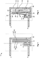
- Fig. 6 shows a second embodiment of the electric switching device 1 of the present invention.
- the electric switching device 1 of Fig. 6 principally corresponds to the switching device 1 of the first embodiment shown in Figs. 1 to 4 .
- the conductor member 34 is not directly connected in series with the second terminal 4. Rather, a second crossover conductor 40' is connecting the conductor member 34 followed by a further conductor member 52, which is in turn connected to the second terminal 4.
- the conductor member 52 extends substantially parallel to the other conductor members 20, 22, 34.
- the conductor member 52 is arranged, with respect to the deflectable conductor member 20, opposite to the conductor member 22, so the conductor member 20 is arranged in between the conductor members 52, 22.
- the conductor member 52 and the deflectable conductor member 20 constitute a second support Lorentz force generator 54. If an electric current is applied along the current path 16, a second enforcing Lorentz force 56 is generated, which acts between the conductor members 52 and 20. Since the current is of the same direction as in the conductor members 20, 52, the second enforcing Lorentz force 56 will act to attract the conductor members 20, 52 to each other, resulting in the deformation of the deflectable conductor member 20 towards the conductor member 52. Thus, the second enforcing Lorentz force 56 may directly act on the contact sub-assembly as a further amplifying contact force 25. To keep Fig. 6 simple, the by-product Lorentz forces generated between the conductor members 22, 34 and 52 are omitted in Fig. 6 .
- the deflectable conductor member 20 is a joint conductor member 38 of the Lorentz force generator 18, of the first support Lorentz force generator 32 as well as of the second support Lorentz force generator 54.
- Fig. 7 shows another electric switching device using Lorentz force.
- the electric switching device 1 of Fig. 7 principally corresponds to the switching device 1 shown in Fig 5 .
- the conductor member 34 is not directly connected in series with the second terminal 4. Rather, a second crossover conductor 40' is connecting the conductor member 34 with a further conductor member 52, which is in turn connected to the second terminal 4.
- the conductor member 52 extends substantially parallel to the other conductor members 20, 22, 34.
- the conductor member 52 is arranged, with respect to the conductor member 22, opposite to the deflectable conductor member 20, so the conductor member 22 is arranged in between the conductor members 52, 20, similar to the configuration of the Lorentz force generator 18 and the support Lorentz force generator 32 of Figs. 1 to 4 .
- the conductor member 52 and the deflectable conductor member 20 constitute a second support Lorentz force generator 54. If an electric current is applied along the current path 16, a second enforcing Lorentz force 56 is generated, which acts between the conductor members 52 and 20. Since the current is of opposite direction in the conductor members 20, 52, the second enforcing Lorentz force 56 will act to push the conductor members 20, 52 away from each other. Thus, the second enforcing Lorentz force 56 may directly act on the contact sub-assembly as a further amplifying contact force 25. To keep Fig. 7 simple, the by-product Lorentz force 42 generated between the conductor members 22, 34 and 52 is omitted in Fig. 7 .
- the deflectable conductor member 20 is a joint conductor member 38 of the Lorentz force generator 18, of the first support Lorentz force generator 32 as well as of the second support Lorentz force generator 54.
- the illustrated embodiments of the electric switching device 1 according to the invention may be furthermore defined by adding additional conductor members constituting further support Lorentz force generators, which may further amplify the contact force biasing the contact sub-assembly 6 in the connecting position 12. In this way, a compact electric switching device 1 generating a very high contact force 25 biasing the contact sub-assembly 6 in the connecting position 12 may be provided.
Landscapes
- Physics & Mathematics (AREA)
- Electromagnetism (AREA)
- Contacts (AREA)
- Micromachines (AREA)
- Arc-Extinguishing Devices That Are Switches (AREA)
- Switch Cases, Indication, And Locking (AREA)
- Gas-Insulated Switchgears (AREA)
Claims (12)
- Dispositif de commutation électrique (1), tel qu'un relais, comprenant- des première et deuxième bornes (2, 4),- un sous-ensemble de contact (6) comportant au moins deux éléments de contact (8, 10) et configuré pour être déplacé d'une position de connexion (12), dans laquelle les éléments de contact (8, 10) entrent en contact entre eux, jusqu'à une position d'interruption (14), dans laquelle les éléments de contact (8, 10) sont espacés entre eux,- un chemin de courant (16) qui s'étend dans la position de connexion (12) du sous-ensemble de contact (6) depuis la première borne (2) via le sous-ensemble de contact (6) jusqu'à la deuxième borne (4), ledit chemin de courant (16) étant interrompu dans la position d'interruption (14) du sous-ensemble de contact (6),- un générateur de force de Lorentz (18) comprenant au moins deux éléments conducteurs (20, 22) situés dans le chemin de courant (16) et agencés pour générer une force de Lorentz (24) qui agit sur les éléments conducteurs (20, 22) et génère une force de contact (25) qui pousse le sous-ensemble de contact (6) en position de connexion (12), et- au moins un générateur de force de Lorentz d'appoint (32) agencé pour générer une force de Lorentz de renfort (36) qui augmente la force de contact (25) en poussant le sous-ensemble de contact (6) dans la position de connexion (12), et- un élément conducteur adjoint (38) qui est un élément conducteur (20) du générateur de force de Lorentz (18) et également un élément conducteur (20) dudit au moins un générateur de force de Lorentz d'appoint (32), dans lequel l'élément conducteur adjoint (38) est agencé de manière adjacente à un élément conducteur (22) du générateur de force de Lorentz (18),caractérisé en ce que
un élément conducteur (34) dudit au moins un générateur de force de Lorentz d'appoint (32) est agencé de manière adjacente à l'élément conducteur (22) du générateur de force de Lorentz (18) opposé à l'élément conducteur adjoint (38). - Dispositif de commutation électrique (1) selon la revendication 1, dans lequel ledit au moins un générateur de force de Lorentz d'appoint (32) comprend au moins deux éléments conducteurs (20, 34) situés dans le chemin de courant (16) et agencés pour générer une force de Lorentz de renfort (36) qui agit sur les éléments conducteurs.
- Dispositif de commutation électrique (1) selon la revendication 1 ou 2, dans lequel au moins l'un des éléments conducteurs (20) est configuré pour être dévié par la force de Lorentz (24) et/ou par la force de Lorentz de renfort (36) par rapport à un état sans courant.
- Dispositif de commutation électrique (1) selon la revendication 3, dans lequel l'élément conducteur qui peut être dévié (20) est pourvu d'une extrémité fixe (26) et d'une extrémité mobile (28) opposée à l'extrémité fixe (26).
- Dispositif de commutation électrique (1) selon la revendication 4, dans lequel l'extrémité mobile (28) de l'élément conducteur qui peut être dévié (20) est pourvue d'un élément de contact (10).
- Dispositif de commutation électrique (1) selon l'une quelconque des revendications 1 à 5, dans lequel lesdits au moins deux éléments conducteurs (20, 22) du générateur de force de Lorentz (18) sont fixés l'un à l'autre.
- Dispositif de commutation électrique (1) selon l'une quelconque des revendications 2 à 6, dans lequel les éléments conducteurs (20, 22) du générateur de force de Lorentz (18) et/ou les éléments conducteurs (20, 34) dudit au moins un générateur de force de Lorentz d'appoint (32) sont connectés en série, et de préférence tous les éléments conducteurs (20, 22, 34, 52) du générateur de force de Lorentz (18) et tous les générateurs de force de Lorentz de renfort (32, 54) sont connectés en série.
- Dispositif de commutation électrique (1) selon l'une quelconque des revendications 2 à 7, dans lequel lesdits au moins deux éléments conducteurs (20, 22) du générateur de force de Lorentz (18) et/ou lesdits au moins deux éléments conducteurs (20, 34) dudit au moins un générateur de force de Lorentz d'appoint (32) s'étendent parallèlement entre eux.
- Dispositif de commutation électrique (1) selon la revendication 8, dans lequel au moins un élément conducteur (20, 22) du générateur de force de Lorentz (18) et au moins un élément conducteur (34) dudit au moins un générateur de force de Lorentz d'appoint (32) s'étendent parallèlement entre eux.
- Dispositif de commutation électrique (1) selon la revendication 9, dans lequel tous les éléments conducteurs (20, 22) du générateur de force de Lorentz (18) et tous les éléments conducteurs (20, 34, 54) dudit au moins un générateur de force de Lorentz d'appoint (32, 54) s'étendent parallèlement entre eux.
- Dispositif de commutation électrique (1) selon les revendications 1 à 10, dans lequel l'élément conducteur adjoint (38) est un élément conducteur (20) qui peut être dévié.
- Dispositif de commutation électrique (1) selon l'une quelconque des revendications 2 à 11, dans lequel lesdits au moins deux éléments conducteurs (20, 22) du générateur de force de Lorentz (18) et/ou lesdits au moins deux éléments conducteurs (20, 34) dudit au moins un générateur de force de Lorentz d'appoint (32) s'étendent de manière adjacente entre eux.
Priority Applications (9)
| Application Number | Priority Date | Filing Date | Title |
|---|---|---|---|
| EP13169164.4A EP2806441B1 (fr) | 2013-05-24 | 2013-05-24 | Dispositif de commutation électrique avec une force de Lorentz améliorée |
| MX2015016128A MX354322B (es) | 2013-05-24 | 2014-05-08 | Dispositivo electrico de conmutacion con mejorada polarizacion de fuerza de lorentz. |
| CN201480029935.0A CN105247643B (zh) | 2013-05-24 | 2014-05-08 | 具有增强洛伦兹力偏压的电气开关设备 |
| CA2910505A CA2910505A1 (fr) | 2013-05-24 | 2014-05-08 | Dispositif de commutateur electrique comportant une polarisation accrue par force de lorentz |
| PCT/EP2014/059404 WO2014187673A1 (fr) | 2013-05-24 | 2014-05-08 | Dispositif de commutateur électrique comportant une polarisation accrue par force de lorentz |
| JP2016514323A JP6622188B2 (ja) | 2013-05-24 | 2014-05-08 | ローレンツ力バイアスが向上された電気スイッチデバイス |
| BR112015029016A BR112015029016A2 (pt) | 2013-05-24 | 2014-05-08 | Dispositivo de ligação elétrica com predisposição da força de lorentz acentuada |
| KR1020157035507A KR20160011648A (ko) | 2013-05-24 | 2014-05-08 | 보강된 로렌츠 힘 편이를 갖는 전기 스위칭 장치 |
| US14/942,413 US9691562B2 (en) | 2013-05-24 | 2015-11-16 | Electric switching device with enhanced Lorentz force bias |
Applications Claiming Priority (1)
| Application Number | Priority Date | Filing Date | Title |
|---|---|---|---|
| EP13169164.4A EP2806441B1 (fr) | 2013-05-24 | 2013-05-24 | Dispositif de commutation électrique avec une force de Lorentz améliorée |
Publications (2)
| Publication Number | Publication Date |
|---|---|
| EP2806441A1 EP2806441A1 (fr) | 2014-11-26 |
| EP2806441B1 true EP2806441B1 (fr) | 2017-07-12 |
Family
ID=48482957
Family Applications (1)
| Application Number | Title | Priority Date | Filing Date |
|---|---|---|---|
| EP13169164.4A Not-in-force EP2806441B1 (fr) | 2013-05-24 | 2013-05-24 | Dispositif de commutation électrique avec une force de Lorentz améliorée |
Country Status (9)
| Country | Link |
|---|---|
| US (1) | US9691562B2 (fr) |
| EP (1) | EP2806441B1 (fr) |
| JP (1) | JP6622188B2 (fr) |
| KR (1) | KR20160011648A (fr) |
| CN (1) | CN105247643B (fr) |
| BR (1) | BR112015029016A2 (fr) |
| CA (1) | CA2910505A1 (fr) |
| MX (1) | MX354322B (fr) |
| WO (1) | WO2014187673A1 (fr) |
Families Citing this family (15)
| Publication number | Priority date | Publication date | Assignee | Title |
|---|---|---|---|---|
| EP3101678B1 (fr) * | 2015-06-01 | 2017-09-13 | Wöhner GmbH & Co. KG Elektrotechnische Systeme | Disjoncteur |
| JP6132043B1 (ja) * | 2016-02-23 | 2017-05-24 | オムロン株式会社 | 電力開閉装置 |
| CN106504949A (zh) * | 2016-11-25 | 2017-03-15 | 厦门宏发电力电器有限公司 | 一种能够抵抗短路电流的磁保持继电器 |
| ES2949563T3 (es) | 2016-11-25 | 2023-09-29 | Xiamen Hongfa Electric Power Controls Co Ltd | Relé de enclavamiento magnético capaz de posicionar con precisión un circuito magnético |
| JP7066996B2 (ja) * | 2017-08-10 | 2022-05-16 | オムロン株式会社 | 電磁継電器 |
| CN109427506B (zh) * | 2017-08-25 | 2020-11-20 | 佛山市顺德区美的电热电器制造有限公司 | 压力开关及电压力锅 |
| US11368031B2 (en) | 2017-11-08 | 2022-06-21 | Eaton Intelligent Power Limited | Power distribution and circuit protection for a mobile application having a high efficiency inverter |
| US11070049B2 (en) | 2017-11-08 | 2021-07-20 | Eaton Intelligent Power Limited | System, method, and apparatus for power distribution in an electric mobile application using a combined breaker and relay |
| CN116742575A (zh) | 2017-11-08 | 2023-09-12 | 伊顿智能动力有限公司 | 用于电动移动应用的电源分配单元和熔断器管理 |
| US11108225B2 (en) | 2017-11-08 | 2021-08-31 | Eaton Intelligent Power Limited | System, method, and apparatus for power distribution in an electric mobile application using a combined breaker and relay |
| EP3719825A1 (fr) * | 2017-11-27 | 2020-10-07 | Panasonic Intellectual Property Management Co., Ltd. | Dispositif de contact, relais électromagnétique et appareil électrique |
| JP6822436B2 (ja) | 2018-03-30 | 2021-01-27 | オムロン株式会社 | リレー |
| US11689010B2 (en) | 2019-02-22 | 2023-06-27 | Eaton Intelligent Power Limited | Coolant fitting promoting turbulent flow |
| WO2021009217A2 (fr) | 2019-07-15 | 2021-01-21 | Eaton Intelligent Power Limited | Distribution de puissance et protection de circuit d'application mobile comportant un onduleur à haut rendement |
| DE102020205869B4 (de) * | 2020-05-11 | 2023-08-03 | Siemens Aktiengesellschaft | Elektromagnetisch unterstützter Antrieb für einen Leistungsschalter mit Vakuumröhre |
Family Cites Families (23)
| Publication number | Priority date | Publication date | Assignee | Title |
|---|---|---|---|---|
| US3593227A (en) * | 1968-02-28 | 1971-07-13 | Gennady Fedosievich Mitskevich | Automatic electrodynamic blowoff breaker with stationary contact form of two series wound u-shaped members |
| FR2185853B1 (fr) * | 1972-05-26 | 1977-12-30 | Merlin Gerin | |
| US4467301A (en) * | 1982-08-27 | 1984-08-21 | Essex Group, Inc. | Electric switch having enhanced fault current capability |
| JPS63237317A (ja) * | 1987-03-25 | 1988-10-03 | 松下電工株式会社 | 接点装置 |
| US4849590A (en) * | 1988-04-01 | 1989-07-18 | Kohler Company | Electric switch with counteracting electro-electro-dynamic forces |
| DE4026425C1 (fr) * | 1990-08-21 | 1992-02-27 | Siemens Ag, 8000 Muenchen, De | |
| SI9300215A (sl) * | 1992-05-15 | 1993-12-31 | Siemens Ag | Priprava s kontaktno vzmetjo za rele za prevajanje in preklapljanje velikih tokov |
| DE19715261C1 (de) * | 1997-04-12 | 1998-12-10 | Gruner Ag | Relais |
| US6034581A (en) * | 1998-06-30 | 2000-03-07 | Siemens Energy & Automation, Inc. | Remote controlled circuit breaker |
| KR100442068B1 (ko) * | 1999-10-14 | 2004-07-30 | 마츠시타 덴코 가부시키가이샤 | 접점 장치 |
| DE10162585C1 (de) * | 2001-12-19 | 2003-04-24 | Gruner Ag | Prellreduziertes Relais |
| JP2006032131A (ja) * | 2004-07-16 | 2006-02-02 | Matsushita Electric Works Ltd | 接点機構およびそれを用いるパワーリレー |
| US7772943B2 (en) * | 2006-07-13 | 2010-08-10 | Siemens Industry, Inc. | Design and method for keeping electrical contacts closed during short circuits |
| US7710224B2 (en) * | 2007-08-01 | 2010-05-04 | Clodi, L.L.C. | Electromagnetic relay assembly |
| US7659800B2 (en) * | 2007-08-01 | 2010-02-09 | Philipp Gruner | Electromagnetic relay assembly |
| DE102008005115A1 (de) * | 2008-01-14 | 2009-07-16 | Siemens Aktiengesellschaft | Schaltgerät, insbesondere Leistungsschaltgerät, mit zwei in Reihe, geschalteten Schaltkontaktpaaren zur Unterbrechung einer Strombahn |
| JP5131218B2 (ja) * | 2008-09-12 | 2013-01-30 | アンデン株式会社 | 電磁継電器 |
| EP2251887B1 (fr) * | 2009-05-15 | 2016-03-16 | Abb Ag | Dispositif de déclenchement électromagnétique |
| DE102010017872B4 (de) * | 2010-04-21 | 2012-06-06 | Saia-Burgess Dresden Gmbh | Bistabiles Kleinrelais großer Leistung |
| US8564386B2 (en) * | 2011-01-18 | 2013-10-22 | Tyco Electronics Corporation | Electrical switching device |
| JP5585550B2 (ja) | 2011-07-18 | 2014-09-10 | アンデン株式会社 | 継電器 |
| JP5923749B2 (ja) * | 2011-07-27 | 2016-05-25 | パナソニックIpマネジメント株式会社 | 接点装置及び該接点装置を用いた電磁リレー |
| CN102903576B (zh) * | 2012-10-27 | 2015-06-03 | 东莞市三友联众电器有限公司 | 磁保持继电器的簧片开关组件 |
-
2013
- 2013-05-24 EP EP13169164.4A patent/EP2806441B1/fr not_active Not-in-force
-
2014
- 2014-05-08 JP JP2016514323A patent/JP6622188B2/ja not_active Expired - Fee Related
- 2014-05-08 BR BR112015029016A patent/BR112015029016A2/pt active Search and Examination
- 2014-05-08 MX MX2015016128A patent/MX354322B/es active IP Right Grant
- 2014-05-08 KR KR1020157035507A patent/KR20160011648A/ko not_active Abandoned
- 2014-05-08 WO PCT/EP2014/059404 patent/WO2014187673A1/fr active Application Filing
- 2014-05-08 CA CA2910505A patent/CA2910505A1/fr not_active Abandoned
- 2014-05-08 CN CN201480029935.0A patent/CN105247643B/zh not_active Expired - Fee Related
-
2015
- 2015-11-16 US US14/942,413 patent/US9691562B2/en active Active
Also Published As
| Publication number | Publication date |
|---|---|
| US9691562B2 (en) | 2017-06-27 |
| CA2910505A1 (fr) | 2014-11-27 |
| CN105247643A (zh) | 2016-01-13 |
| KR20160011648A (ko) | 2016-02-01 |
| JP2016522548A (ja) | 2016-07-28 |
| EP2806441A1 (fr) | 2014-11-26 |
| MX2015016128A (es) | 2016-08-08 |
| WO2014187673A1 (fr) | 2014-11-27 |
| JP6622188B2 (ja) | 2019-12-18 |
| CN105247643B (zh) | 2017-12-08 |
| BR112015029016A2 (pt) | 2017-10-03 |
| MX354322B (es) | 2018-02-26 |
| US20160071677A1 (en) | 2016-03-10 |
Similar Documents
| Publication | Publication Date | Title |
|---|---|---|
| EP2806441B1 (fr) | Dispositif de commutation électrique avec une force de Lorentz améliorée | |
| EP2782110B1 (fr) | Dispositif de commutation électrique activé par force de Lorentz | |
| EP1879204B1 (fr) | Conception et procédé pour maintenir les contacts électriques fermés pendant les court circuits | |
| CN103545153A (zh) | 保护开关装置和磁轭 | |
| CN110235215B (zh) | 用于高强度电流切换应用的改进的接触器装置 | |
| CN103515154A (zh) | 在介电液体中使用的接触器装置 | |
| US10665407B2 (en) | Spring member for an electric switching device such as a cradle relay | |
| GB2562866A (en) | Contact system and relay having the same | |
| PL188169B1 (pl) | Wyłącznik elektryczny | |
| CN105393328B (zh) | 电开关触头和具有相同电开关触头的开关设备 | |
| CN111900006B (zh) | 用于电气开关的限制器极和包括该限制器极的dc电气开关 | |
| CN113841214B (zh) | 开关系统的开关触点系统 | |
| EP3078043B1 (fr) | Arrangement de contacts pour relais a courant fort | |
| EP3059749B1 (fr) | Disjoncteur comprenant des géométries de trajet de courant qui augmentent le niveau d'auto-ecartement des contacts | |
| JP2022524883A (ja) | 改良された接触面を有するコンタクトを備えた電気アセンブリ | |
| EP2482295B1 (fr) | Relais avec plusieurs contacts | |
| JP2016170861A (ja) | 電気回路切替装置及び電気回路切替システム | |
| JP2020009571A (ja) | 可動端子片構造およびこれを備えたリレー | |
| SE501134C2 (sv) | Fångkontaktanordning och användning av dito vid utdragbar högspänningsapparat | |
| JP2016177914A (ja) | 開閉装置 | |
| JP2014139913A5 (fr) |
Legal Events
| Date | Code | Title | Description |
|---|---|---|---|
| PUAI | Public reference made under article 153(3) epc to a published international application that has entered the european phase |
Free format text: ORIGINAL CODE: 0009012 |
|
| 17P | Request for examination filed |
Effective date: 20130524 |
|
| AK | Designated contracting states |
Kind code of ref document: A1 Designated state(s): AL AT BE BG CH CY CZ DE DK EE ES FI FR GB GR HR HU IE IS IT LI LT LU LV MC MK MT NL NO PL PT RO RS SE SI SK SM TR |
|
| AX | Request for extension of the european patent |
Extension state: BA ME |
|
| R17P | Request for examination filed (corrected) |
Effective date: 20150522 |
|
| RBV | Designated contracting states (corrected) |
Designated state(s): AL AT BE BG CH CY CZ DE DK EE ES FI FR GB GR HR HU IE IS IT LI LT LU LV MC MK MT NL NO PL PT RO RS SE SI SK SM TR |
|
| GRAP | Despatch of communication of intention to grant a patent |
Free format text: ORIGINAL CODE: EPIDOSNIGR1 |
|
| RIC1 | Information provided on ipc code assigned before grant |
Ipc: H01H 50/54 20060101ALI20160330BHEP Ipc: H01H 1/54 20060101AFI20160330BHEP |
|
| INTG | Intention to grant announced |
Effective date: 20160415 |
|
| GRAP | Despatch of communication of intention to grant a patent |
Free format text: ORIGINAL CODE: EPIDOSNIGR1 |
|
| INTC | Intention to grant announced (deleted) | ||
| INTG | Intention to grant announced |
Effective date: 20160829 |
|
| GRAJ | Information related to disapproval of communication of intention to grant by the applicant or resumption of examination proceedings by the epo deleted |
Free format text: ORIGINAL CODE: EPIDOSDIGR1 |
|
| INTC | Intention to grant announced (deleted) | ||
| GRAP | Despatch of communication of intention to grant a patent |
Free format text: ORIGINAL CODE: EPIDOSNIGR1 |
|
| INTG | Intention to grant announced |
Effective date: 20170130 |
|
| GRAS | Grant fee paid |
Free format text: ORIGINAL CODE: EPIDOSNIGR3 |
|
| GRAA | (expected) grant |
Free format text: ORIGINAL CODE: 0009210 |
|
| AK | Designated contracting states |
Kind code of ref document: B1 Designated state(s): AL AT BE BG CH CY CZ DE DK EE ES FI FR GB GR HR HU IE IS IT LI LT LU LV MC MK MT NL NO PL PT RO RS SE SI SK SM TR |
|
| REG | Reference to a national code |
Ref country code: GB Ref legal event code: FG4D |
|
| REG | Reference to a national code |
Ref country code: CH Ref legal event code: EP |
|
| REG | Reference to a national code |
Ref country code: AT Ref legal event code: REF Ref document number: 909064 Country of ref document: AT Kind code of ref document: T Effective date: 20170715 |
|
| REG | Reference to a national code |
Ref country code: IE Ref legal event code: FG4D |
|
| REG | Reference to a national code |
Ref country code: DE Ref legal event code: R096 Ref document number: 602013023304 Country of ref document: DE |
|
| REG | Reference to a national code |
Ref country code: DE Ref legal event code: R082 Ref document number: 602013023304 Country of ref document: DE Representative=s name: HARRASZ, JULIA, DE Ref country code: DE Ref legal event code: R082 Ref document number: 602013023304 Country of ref document: DE Representative=s name: MURGITROYD & COMPANY, DE |
|
| REG | Reference to a national code |
Ref country code: DE Ref legal event code: R082 Ref document number: 602013023304 Country of ref document: DE Representative=s name: MURGITROYD & COMPANY, DE |
|
| REG | Reference to a national code |
Ref country code: NL Ref legal event code: MP Effective date: 20170712 |
|
| REG | Reference to a national code |
Ref country code: LT Ref legal event code: MG4D |
|
| REG | Reference to a national code |
Ref country code: AT Ref legal event code: MK05 Ref document number: 909064 Country of ref document: AT Kind code of ref document: T Effective date: 20170712 |
|
| PG25 | Lapsed in a contracting state [announced via postgrant information from national office to epo] |
Ref country code: SE Free format text: LAPSE BECAUSE OF FAILURE TO SUBMIT A TRANSLATION OF THE DESCRIPTION OR TO PAY THE FEE WITHIN THE PRESCRIBED TIME-LIMIT Effective date: 20170712 Ref country code: FI Free format text: LAPSE BECAUSE OF FAILURE TO SUBMIT A TRANSLATION OF THE DESCRIPTION OR TO PAY THE FEE WITHIN THE PRESCRIBED TIME-LIMIT Effective date: 20170712 Ref country code: NO Free format text: LAPSE BECAUSE OF FAILURE TO SUBMIT A TRANSLATION OF THE DESCRIPTION OR TO PAY THE FEE WITHIN THE PRESCRIBED TIME-LIMIT Effective date: 20171012 Ref country code: AT Free format text: LAPSE BECAUSE OF FAILURE TO SUBMIT A TRANSLATION OF THE DESCRIPTION OR TO PAY THE FEE WITHIN THE PRESCRIBED TIME-LIMIT Effective date: 20170712 Ref country code: LT Free format text: LAPSE BECAUSE OF FAILURE TO SUBMIT A TRANSLATION OF THE DESCRIPTION OR TO PAY THE FEE WITHIN THE PRESCRIBED TIME-LIMIT Effective date: 20170712 Ref country code: HR Free format text: LAPSE BECAUSE OF FAILURE TO SUBMIT A TRANSLATION OF THE DESCRIPTION OR TO PAY THE FEE WITHIN THE PRESCRIBED TIME-LIMIT Effective date: 20170712 Ref country code: NL Free format text: LAPSE BECAUSE OF FAILURE TO SUBMIT A TRANSLATION OF THE DESCRIPTION OR TO PAY THE FEE WITHIN THE PRESCRIBED TIME-LIMIT Effective date: 20170712 |
|
| PG25 | Lapsed in a contracting state [announced via postgrant information from national office to epo] |
Ref country code: IS Free format text: LAPSE BECAUSE OF FAILURE TO SUBMIT A TRANSLATION OF THE DESCRIPTION OR TO PAY THE FEE WITHIN THE PRESCRIBED TIME-LIMIT Effective date: 20171112 Ref country code: ES Free format text: LAPSE BECAUSE OF FAILURE TO SUBMIT A TRANSLATION OF THE DESCRIPTION OR TO PAY THE FEE WITHIN THE PRESCRIBED TIME-LIMIT Effective date: 20170712 Ref country code: RS Free format text: LAPSE BECAUSE OF FAILURE TO SUBMIT A TRANSLATION OF THE DESCRIPTION OR TO PAY THE FEE WITHIN THE PRESCRIBED TIME-LIMIT Effective date: 20170712 Ref country code: BG Free format text: LAPSE BECAUSE OF FAILURE TO SUBMIT A TRANSLATION OF THE DESCRIPTION OR TO PAY THE FEE WITHIN THE PRESCRIBED TIME-LIMIT Effective date: 20171012 Ref country code: PL Free format text: LAPSE BECAUSE OF FAILURE TO SUBMIT A TRANSLATION OF THE DESCRIPTION OR TO PAY THE FEE WITHIN THE PRESCRIBED TIME-LIMIT Effective date: 20170712 Ref country code: LV Free format text: LAPSE BECAUSE OF FAILURE TO SUBMIT A TRANSLATION OF THE DESCRIPTION OR TO PAY THE FEE WITHIN THE PRESCRIBED TIME-LIMIT Effective date: 20170712 Ref country code: GR Free format text: LAPSE BECAUSE OF FAILURE TO SUBMIT A TRANSLATION OF THE DESCRIPTION OR TO PAY THE FEE WITHIN THE PRESCRIBED TIME-LIMIT Effective date: 20171013 |
|
| REG | Reference to a national code |
Ref country code: FR Ref legal event code: PLFP Year of fee payment: 6 |
|
| REG | Reference to a national code |
Ref country code: DE Ref legal event code: R097 Ref document number: 602013023304 Country of ref document: DE |
|
| PG25 | Lapsed in a contracting state [announced via postgrant information from national office to epo] |
Ref country code: RO Free format text: LAPSE BECAUSE OF FAILURE TO SUBMIT A TRANSLATION OF THE DESCRIPTION OR TO PAY THE FEE WITHIN THE PRESCRIBED TIME-LIMIT Effective date: 20170712 Ref country code: CZ Free format text: LAPSE BECAUSE OF FAILURE TO SUBMIT A TRANSLATION OF THE DESCRIPTION OR TO PAY THE FEE WITHIN THE PRESCRIBED TIME-LIMIT Effective date: 20170712 Ref country code: DK Free format text: LAPSE BECAUSE OF FAILURE TO SUBMIT A TRANSLATION OF THE DESCRIPTION OR TO PAY THE FEE WITHIN THE PRESCRIBED TIME-LIMIT Effective date: 20170712 |
|
| PLBE | No opposition filed within time limit |
Free format text: ORIGINAL CODE: 0009261 |
|
| STAA | Information on the status of an ep patent application or granted ep patent |
Free format text: STATUS: NO OPPOSITION FILED WITHIN TIME LIMIT |
|
| PG25 | Lapsed in a contracting state [announced via postgrant information from national office to epo] |
Ref country code: SM Free format text: LAPSE BECAUSE OF FAILURE TO SUBMIT A TRANSLATION OF THE DESCRIPTION OR TO PAY THE FEE WITHIN THE PRESCRIBED TIME-LIMIT Effective date: 20170712 Ref country code: SK Free format text: LAPSE BECAUSE OF FAILURE TO SUBMIT A TRANSLATION OF THE DESCRIPTION OR TO PAY THE FEE WITHIN THE PRESCRIBED TIME-LIMIT Effective date: 20170712 Ref country code: EE Free format text: LAPSE BECAUSE OF FAILURE TO SUBMIT A TRANSLATION OF THE DESCRIPTION OR TO PAY THE FEE WITHIN THE PRESCRIBED TIME-LIMIT Effective date: 20170712 Ref country code: IT Free format text: LAPSE BECAUSE OF FAILURE TO SUBMIT A TRANSLATION OF THE DESCRIPTION OR TO PAY THE FEE WITHIN THE PRESCRIBED TIME-LIMIT Effective date: 20170712 |
|
| 26N | No opposition filed |
Effective date: 20180413 |
|
| PG25 | Lapsed in a contracting state [announced via postgrant information from national office to epo] |
Ref country code: SI Free format text: LAPSE BECAUSE OF FAILURE TO SUBMIT A TRANSLATION OF THE DESCRIPTION OR TO PAY THE FEE WITHIN THE PRESCRIBED TIME-LIMIT Effective date: 20170712 |
|
| REG | Reference to a national code |
Ref country code: CH Ref legal event code: PL |
|
| REG | Reference to a national code |
Ref country code: BE Ref legal event code: MM Effective date: 20180531 |
|
| PG25 | Lapsed in a contracting state [announced via postgrant information from national office to epo] |
Ref country code: MC Free format text: LAPSE BECAUSE OF FAILURE TO SUBMIT A TRANSLATION OF THE DESCRIPTION OR TO PAY THE FEE WITHIN THE PRESCRIBED TIME-LIMIT Effective date: 20170712 |
|
| REG | Reference to a national code |
Ref country code: IE Ref legal event code: MM4A |
|
| PG25 | Lapsed in a contracting state [announced via postgrant information from national office to epo] |
Ref country code: CH Free format text: LAPSE BECAUSE OF NON-PAYMENT OF DUE FEES Effective date: 20180531 Ref country code: LI Free format text: LAPSE BECAUSE OF NON-PAYMENT OF DUE FEES Effective date: 20180531 |
|
| PG25 | Lapsed in a contracting state [announced via postgrant information from national office to epo] |
Ref country code: LU Free format text: LAPSE BECAUSE OF NON-PAYMENT OF DUE FEES Effective date: 20180524 |
|
| PG25 | Lapsed in a contracting state [announced via postgrant information from national office to epo] |
Ref country code: IE Free format text: LAPSE BECAUSE OF NON-PAYMENT OF DUE FEES Effective date: 20180524 |
|
| PG25 | Lapsed in a contracting state [announced via postgrant information from national office to epo] |
Ref country code: BE Free format text: LAPSE BECAUSE OF NON-PAYMENT OF DUE FEES Effective date: 20180531 |
|
| PG25 | Lapsed in a contracting state [announced via postgrant information from national office to epo] |
Ref country code: MT Free format text: LAPSE BECAUSE OF NON-PAYMENT OF DUE FEES Effective date: 20180524 |
|
| PG25 | Lapsed in a contracting state [announced via postgrant information from national office to epo] |
Ref country code: TR Free format text: LAPSE BECAUSE OF FAILURE TO SUBMIT A TRANSLATION OF THE DESCRIPTION OR TO PAY THE FEE WITHIN THE PRESCRIBED TIME-LIMIT Effective date: 20170712 |
|
| PG25 | Lapsed in a contracting state [announced via postgrant information from national office to epo] |
Ref country code: PT Free format text: LAPSE BECAUSE OF FAILURE TO SUBMIT A TRANSLATION OF THE DESCRIPTION OR TO PAY THE FEE WITHIN THE PRESCRIBED TIME-LIMIT Effective date: 20170712 Ref country code: HU Free format text: LAPSE BECAUSE OF FAILURE TO SUBMIT A TRANSLATION OF THE DESCRIPTION OR TO PAY THE FEE WITHIN THE PRESCRIBED TIME-LIMIT; INVALID AB INITIO Effective date: 20130524 |
|
| PG25 | Lapsed in a contracting state [announced via postgrant information from national office to epo] |
Ref country code: MK Free format text: LAPSE BECAUSE OF NON-PAYMENT OF DUE FEES Effective date: 20170712 Ref country code: CY Free format text: LAPSE BECAUSE OF FAILURE TO SUBMIT A TRANSLATION OF THE DESCRIPTION OR TO PAY THE FEE WITHIN THE PRESCRIBED TIME-LIMIT Effective date: 20170712 |
|
| PG25 | Lapsed in a contracting state [announced via postgrant information from national office to epo] |
Ref country code: AL Free format text: LAPSE BECAUSE OF FAILURE TO SUBMIT A TRANSLATION OF THE DESCRIPTION OR TO PAY THE FEE WITHIN THE PRESCRIBED TIME-LIMIT Effective date: 20170712 |
|
| PGFP | Annual fee paid to national office [announced via postgrant information from national office to epo] |
Ref country code: FR Payment date: 20200414 Year of fee payment: 8 Ref country code: DE Payment date: 20200512 Year of fee payment: 8 |
|
| PGFP | Annual fee paid to national office [announced via postgrant information from national office to epo] |
Ref country code: GB Payment date: 20200513 Year of fee payment: 8 |
|
| REG | Reference to a national code |
Ref country code: DE Ref legal event code: R119 Ref document number: 602013023304 Country of ref document: DE |
|
| GBPC | Gb: european patent ceased through non-payment of renewal fee |
Effective date: 20210524 |
|
| PG25 | Lapsed in a contracting state [announced via postgrant information from national office to epo] |
Ref country code: GB Free format text: LAPSE BECAUSE OF NON-PAYMENT OF DUE FEES Effective date: 20210524 Ref country code: DE Free format text: LAPSE BECAUSE OF NON-PAYMENT OF DUE FEES Effective date: 20211201 |
|
| PG25 | Lapsed in a contracting state [announced via postgrant information from national office to epo] |
Ref country code: FR Free format text: LAPSE BECAUSE OF NON-PAYMENT OF DUE FEES Effective date: 20210531 |