EP1548701B1 - Kanal mit integrierten akustischen Dämpfer und Verfahren zu dessen Herstellung - Google Patents
Kanal mit integrierten akustischen Dämpfer und Verfahren zu dessen Herstellung Download PDFInfo
- Publication number
- EP1548701B1 EP1548701B1 EP04106752.1A EP04106752A EP1548701B1 EP 1548701 B1 EP1548701 B1 EP 1548701B1 EP 04106752 A EP04106752 A EP 04106752A EP 1548701 B1 EP1548701 B1 EP 1548701B1
- Authority
- EP
- European Patent Office
- Prior art keywords
- conduit
- silencer
- attenuators
- quarter
- segment
- Prior art date
- Legal status (The legal status is an assumption and is not a legal conclusion. Google has not performed a legal analysis and makes no representation as to the accuracy of the status listed.)
- Expired - Lifetime
Links
Images


Classifications
-
- F—MECHANICAL ENGINEERING; LIGHTING; HEATING; WEAPONS; BLASTING
- F01—MACHINES OR ENGINES IN GENERAL; ENGINE PLANTS IN GENERAL; STEAM ENGINES
- F01N—GAS-FLOW SILENCERS OR EXHAUST APPARATUS FOR MACHINES OR ENGINES IN GENERAL; GAS-FLOW SILENCERS OR EXHAUST APPARATUS FOR INTERNAL-COMBUSTION ENGINES
- F01N13/00—Exhaust or silencing apparatus characterised by constructional features
- F01N13/18—Construction facilitating manufacture, assembly, or disassembly
-
- F—MECHANICAL ENGINEERING; LIGHTING; HEATING; WEAPONS; BLASTING
- F01—MACHINES OR ENGINES IN GENERAL; ENGINE PLANTS IN GENERAL; STEAM ENGINES
- F01N—GAS-FLOW SILENCERS OR EXHAUST APPARATUS FOR MACHINES OR ENGINES IN GENERAL; GAS-FLOW SILENCERS OR EXHAUST APPARATUS FOR INTERNAL-COMBUSTION ENGINES
- F01N1/00—Silencing apparatus characterised by method of silencing
- F01N1/003—Silencing apparatus characterised by method of silencing by using dead chambers communicating with exhaust gas flow passages
-
- G—PHYSICS
- G10—MUSICAL INSTRUMENTS; ACOUSTICS
- G10K—SOUND-PRODUCING DEVICES; METHODS OR DEVICES FOR PROTECTING AGAINST, OR FOR DAMPING, NOISE OR OTHER ACOUSTIC WAVES IN GENERAL; ACOUSTICS NOT OTHERWISE PROVIDED FOR
- G10K11/00—Methods or devices for transmitting, conducting or directing sound in general; Methods or devices for protecting against, or for damping, noise or other acoustic waves in general
- G10K11/16—Methods or devices for protecting against, or for damping, noise or other acoustic waves in general
- G10K11/172—Methods or devices for protecting against, or for damping, noise or other acoustic waves in general using resonance effects
Definitions
- the present invention relates to the field of gaseous fluid circulation conduits and pipes, in particular those forming part of the equipment and parts of vehicles with an internal combustion engine and has for its object a conduit or pipe of the aforementioned type comprising integrated acoustic attenuators, and a method for the production thereof.
- Document EP 0 646 447 A discloses a method of producing a gaseous fluid circulation conduit or pipe in accordance with the preamble of claim 12.
- conduit/attenuator assembly of this type should be easy and inexpensive to produce, and have high vibration and impact resistance.
- the object of the present invention is, in particular, to respond to the aforementioned demand.
- the invention relates to a gaseous fluid circulation conduit or pipe, provided with an arrangement of acoustic attenuators, extending laterally in the region of an intermediate segment of said conduit or pipe and opening into the interior volume of said segment, wherein said arrangement comprises a multi-hole silencer and two quarter-wave attenuators, said quarter-wave attenuators being disposed so as to be acoustically coupled to said silencer, wherein said intermediate segment has a substantially rectilinear structure with a central circulation axis or median axis, and wherein the multi-hole silencer, on the one hand, and the two quarter-wave attenuators, on the other hand, are located either side of said median axis of said segment, so as to form, together with this silencer and these two attenuators, a single-piece structure with a substantially flat configuration or constitution.
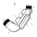
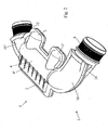
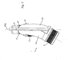
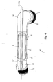
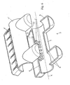
- FIGS 1 to 4 and 7 of the accompanying drawings show a conduit or pipe 1 for the circulation of gaseous fluid, in particular a gaseous mixture of various gaseous fluids, provided with an arrangement of acoustic attenuators 2, 3, 3' extending laterally in the region of an intermediate segment 4 of said conduit or pipe 1 and opening into the interior volume of said segment 4.
- gaseous fluid in particular a gaseous mixture of various gaseous fluids
- acoustic attenuators 2, 3, 3' extending laterally in the region of an intermediate segment 4 of said conduit or pipe 1 and opening into the interior volume of said segment 4.
- said arrangement of attenuators comprises a multi-hole silencer 2 and two quarter-wave attenuators 3 and 3', said quarter-wave attenuators 3 and 3' being disposed so as to be acoustically coupled to said silencer 2.
- Said intermediate segment 4 has a structure that is substantially rectilinear with a central circulation axis or median axis X, and the multi-hole silencer 2, on the one hand, and the two quarter-wave attenuators 3 and 3', on the other hand, are located either side of said median axis X of said segment 4, so as to form, together with this silencer 2 and these two attenuators 3 and 3', a single-piece structure 5 with a substantially flat configuration or constitution.
- the multi-hole silencer 2 and the two quarter-wave attenuators 3 and 3' have, viewed in lateral elevation in the median plane PM of the structure 5 with a flat configuration, formed by the multi-hole silencer 2/intermediate segment 4/quarter-wave attenuators 3 and 3' assembly, or in a plane parallel to this median plane, a thickness or an exterior height at most substantially equal to the thickness or the exterior height of the intermediate segment 4, in the direction perpendicular to said median plane PM, said median plane PM containing the central circulation or median axis X of said intermediate segment 4.
- the multi-hole silencer 2 consists of a caisson or similar closed hollow body, formed on the wall of the intermediate segment 4 and communicating with the interior volume thereof through a plurality of openings 2', and each of the two quarter-wave attenuators 3 and 3' consists of a hollow body in the form of a deformation towards the exterior, forming a cavity in the wall of the intermediate segment 4, the two attenuators 3 and 3' having different dimensions, in particular different depths.
- openings 2' may, for example, be in the form of through-perforations provided in the wall portion, common with the silencer 2, of the intermediate segment 4, and forming a wall portion contributing to the delimitation of the interior volume of said silencer.
- the openings 2' may also be in the form of through-perforations provided in a plate or the like, made of a metallic or rigid synthetic material, mounted in a cut-out of the wall portion, common with the silencer 2, of the intermediate segment 4, the edges of said plate defining baffle structures with the edges of said cut-out.
- the multi-hole silencer 2 may, for example, have a parallelepiped, preferably rectangular, shape, and each of the quarter-wave attenuators 3 and 3' consist of a cylindrical cavity, with a circular or non-circular section.
- the large opposite walls delimiting the sound-proofing caisson of the multi-hole silencer in the form of a flattened parallelepiped, may advantageously be connected to the wall of the intermediate segment 4 by reinforcing ribs 4', rigidifying their mutual connection.
- the respective relative dispositions of the quarter-wave attenuators 3 and 3' in relation to the multi-hole silencer 2, in the direction of fluid flow in the segment 4, may be varied, as a function, in particular, of the desired attenuation profile.
- the two attenuators 3 and 3' may thus both be located upstream or downstream of said silencer 2, or alternatively, as shown in the accompanying figures, be located facing each other, either side of the apertures forming communication openings 2' between the internal volumes of said silencer 2 and said intermediate segment 4.
- the conduit or pipe consists of a conduit 1 through which the gaseous flow emitted from a turbocompressor of an internal combustion engine passes, it may advantageously be provided that the shapes, the dimensions, the relative dispositions and the degree of acoustic coupling of the multi-hole silencer 2 and the two quarter-wave attenuators 3 and 3' are defined in such a way that the arrangement of acoustic attenuators 2, 3, 3' has an attenuation of at least 20 dB in the 1,500 Hz to 3,200 Hz frequency range.
- the two quarter-wave attenuators 3 and 3' allow attenuation to be reinforced in the region of the extreme values of the frequency range to be attenuated, and will consequently be configured and dimensioned with this object.
- At least the assembly formed by said intermediate segment 4 with the multi-hole silencer 2 and the two quarter-wave attenuators 3 and 3' is formed by joining two single-piece parts 7 and 7', in the region of assembly zones 6 located in the median plane PM of the structure with a flat configuration 5 formed by the aforementioned assembly, containing the central circulation or median X axis of the intermediate rectilinear conduit segment 4, each of the single-piece parts 7, 7' being formed by wall portions of the intermediate segment 4, the multi-hole silencer 2 and two quarter-wave attenuators 3 and 3'.
- any conduit segments and/or additional fittings also forming part of the conduit or pipe 1 may be connected to the opposite ends of the intermediate segment 4 by an appropriate joining technique, after production of the structure 5.
- the conduit or pipe 1 is formed by joining two constituent parts 8 and 8', each of a single piece, a first part 8 comprising a first tubular fitting 9, optionally a wall portion of a first conduit segment, first wall portions 7 of the multi-hole silencer 2/intermediate segment 4/quarter-wave attenuators 3 and 3' assembly, optionally a wall portion of a third conduit segment 11 and a second tubular fitting 12, and a second part 8' comprising second wall portions 7' of the multi-hole silencer 2/intermediate segment 4/quarter-wave attenuators 3 and 3' assembly, which second wall portions 7' are complementary to the aforementioned first wall portions 7, and, optionally, wall portions 10', 11' complementary to the first and/or third conduit segment(s), the assembly zones 6 of these two constituent parts 8, 8' preferably being located, in the region of the structure 5 with a flat configuration formed by the aforementioned assembly, in the median plane PM of this structure.
- the first and/or the third conduit segment(s) 10 and 10', 11 and 11' may optionally be omitted, the corresponding fitting(s) 9, 12 then being directly contiguous to the intermediate segment 4 (variants not shown).
- Each of the constituent single-piece parts 7, 7'; 8, 8' is produced by injection-moulding of thermoplastic material(s), optionally filled or reinforced with fibres, and the joining of the two parts 7, 7'; 8, 8' in the region of their assembly zones consists in vibration welding.
- the openings 2' are provided in the common wall portion between the segment 4 and the silencer 2.
- the openings 2' are provided in a connected plate forming an insert, said plate forming part of the wall portion, common with the silencer 2 and comprising the openings 2', of the intermediate segment 4 is mounted with locking in the corresponding receiving cut-out of this wall portion, in the region of a peripheral groove, and is held by compression between the two parts 7, 7'; 8, 8'.
- the present invention also relates to a method of producing a gaseous fluid circulation conduit or pipe of the above-described type.
- This method is characterised in that it consists in separately producing, by injection moulding, two complementary constituent parts 8 and 8', each of a single piece, i.e. a first part 8 comprising a first tubular fitting 9, optionally a wall portion of a first conduit segment, first wall portions 7 of the multi-hole silencer 2/intermediate segment 4/quarter-wave attenuators 3 and 3' assembly, optionally a wall portion of a third conduit segment 11 and a second tubular fitting 12, and a second part 8' comprising second wall portions 7' of the multi-hole silencer 2/intermediate segment 4/quarter-wave attenuators 3 and 3' assembly, which second wall portions are complementary to the aforementioned first wall portions 7, and, optionally, wall portions 10', 11' complementary to the first and/or third conduit segment(s), and in joining the two complementary constituent parts 8 and 8' by vibration welding, in the region of assembly zones defined by the partition of the walls of the conduit or pipe, the multi-hole silencer 2 and the two quarter-wave attenuators
- the two parts 7 and 7' may first be produced, then joined into a single structure 5 and, finally, the additional (first and third) conduit segments and the fittings 9 and 12 be connected.
- This example will involve additional assembly processes, but will allow greater flexibility with regard to the construction of the final conduit or pipe 1 (possibility of introducing various segments or fittings).
- the complementary wall portions forming, by cooperation and joining, the rectilinear intermediate segment 4 of the conduit or pipe 1 each comprise a part, preferably half, of the through-openings 2' of the multi-hole silencer 2, these openings 2' being formed during the production of the corresponding constituent part 8, 8', by demoulding in an inclined movement in relation to the principal demoulding axis formed by the direction, perpendicular to the imaginary plane containing the assembly zones 6, of the wall portions 7, 7' of the structure 5 with a substantially flat configuration.
- the complementary wall portions forming, by cooperation and joining, the rectilinear intermediate segment 4 may each comprise, in the region of their parts forming, by cooperation, a wall portion common with the multi-hole silencer 2, a cut-out part, these two cut-out parts forming by cooperation, at the moment when the two constituent parts 8 and 8' are joined, a receiving cut-out for a plate or the like comprising openings 2', this plate being mounted in one of said parts 8, 8' prior to assembly and held after assembly in a peripheral groove of the receiving cut-out, by being locked by compression.
Landscapes
- Engineering & Computer Science (AREA)
- Chemical & Material Sciences (AREA)
- Combustion & Propulsion (AREA)
- Mechanical Engineering (AREA)
- General Engineering & Computer Science (AREA)
- Physics & Mathematics (AREA)
- Acoustics & Sound (AREA)
- Multimedia (AREA)
- Exhaust Silencers (AREA)
Claims (15)
- Kanal oder Rohr zum Umlauf gasförmiger Fluide (1) mit entgegengesetztem erstem und zweitem röhrenförmigem Anschlussstück (9, 12), versehen mit einer Anordnung akustischer Dämpfungselemente (2, 3, 3'), die sich in dem Bereich eines Zwischensegmentes (4) des Kanals oder Rohrs seitlich erstrecken und sich in das Innenvolumen des Segmentes öffnen,
wobei die Anordnung einen Mehrloch-Geräuschdämpfer (2) und zwei andere Dämpfungselemente (3 und 3') aufweist, wobei die anderen Dämpfungselemente (3 und 3') angeordnet sind, um mit dem Geräuschdämpfer (2) akustisch gekoppelt zu sein, und das Zwischensegment (4) eine Struktur aufweist, die im Wesentlichen geradlinig zu einer zentralen Umlaufachse oder Mittelachse (X) ist,
wobei der Kanal oder das Rohr (1) dadurch gekennzeichnet ist, dass die zwei Dämpfungselemente (3 und 3') Viertelwellen-Dämpfungselemente sind, dass sich der Mehrloch-Geräuschdämpfer (2) einerseits und die zwei Viertelwellen-Dämpfungselemente (3 und 3') andererseits auf beiden Seiten der Mittelachse (X) des Segmentes (4) befinden, um zusammen mit diesem Geräuschdämpfer (2) und diesen zwei Dämpfungselementen (3 und 3') eine einstückige Struktur (5) mit einer im Wesentlichen flachen Konfiguration oder Konstitution zu bilden, und dass die Struktur (5) aus zwei komplementären einstückigen Bestandteilen (8, 8') hergestellt ist, die jeweils durch Spritzgießen von thermoplastischem (-n) Material (-ien) erhalten wurden und beide durch Vibrationsschweißen verbunden sind, wobei eines der Teile (8, 8') auch mindestens das erste und das zweite röhrenförmige Anschlussstück (9, 12) aufweist. - Kanal nach Anspruch 1, dadurch gekennzeichnet, dass der Mehrloch-Geräuschdämpfer (2) und die zwei Viertelwellen-Dämpfungselemente (3 und 3'), betrachtet im Seitenaufriss in der Mittelebene (PM) der Struktur (5) mit einer flachen Konfiguration, die von der Baugruppe Mehrloch-Geräuschdämpfer (2) / Zwischensegment (4) / Viertelwellen-Dämpfungselemente (3 und 3') gebildet ist, oder in einer Ebene parallel zu dieser Mittelebene, eine Dicke oder eine Außenhöhe von höchstens im Wesentlichen gleich der Dicke oder der Außenhöhe des Zwischensegmentes (4) in der Richtung im rechten Winkel zu der Mittelebene (PM) aufweisen, wobei die Mittelebene (PM) die zentrale Umlauf- oder Mittelachse (X) des Zwischensegmentes (4) enthält.
- Kanal nach einem der Ansprüche 1 oder 2, dadurch gekennzeichnet, dass der Mehrloch-Geräuschdämpfer (2) aus einem Senkkasten oder einem ähnlichen geschlossenen Hohlkörper besteht, der an der Wand des Zwischensegmentes (4) gebildet ist und mit dessen Innenvolumen durch mehrere Durchgangsöffnungen (2'), die in der Wand geschaffen sind, in Verbindung ist und dass jedes der zwei Viertelwellen-Dämpfungselemente (3 und 3') aus einem Hohlkörper in Form einer Verformung nach außen hin besteht, die eine Höhlung in der Wand des Zwischensegmentes (4) bildet, wobei die zwei Dämpfungselemente (3 und 3') unterschiedliche Abmessungen, insbesondere unterschiedliche Tiefen aufweisen.
- Kanal nach Anspruch 3, dadurch gekennzeichnet, dass die Öffnungen (2') in Form von Durchbohrungen vorliegen, die in dem Wandabschnitt des Zwischensegmentes (4) geschaffen sind, der mit dem Geräuschdämpfer (2) gemeinsam ist und einen Wandabschnitt bildet, der zur Abgrenzung des Innenvolumens des Geräuschdämpfers beiträgt.
- Kanal nach Anspruch 3, dadurch gekennzeichnet, dass die Öffnungen (2') in Form von Durchbohrungen vorliegen, die in einer Platte oder dergleichen geschaffen sind, die aus einem metallischen oder steifen synthetischen Material gebildet ist, die in einer Ausnehmung des Wandabschnitts des Zwischensegmentes (4) angebracht ist, der mit dem Geräuschdämpfer (2) gemeinsam ist, wobei die Kanten der Platte mit den Kanten der Ausnehmung Leitblechstrukturen definieren.
- Kanal nach einem der Ansprüche 3 bis 5, dadurch gekennzeichnet, dass der Mehrloch-Geräuschdämpfer (2) eine quaderförmige, vorzugsweise rechteckige Form aufweist und dass jedes der Viertelwellen-Dämpfungselemente (3 und 3') aus einer zylindrischen Höhlung mit einem kreisförmigen oder nicht kreisförmigen Querschnitt besteht.
- Kanal nach einem der Ansprüche 1 bis 6, dadurch gekennzeichnet, dass die Formen, die Abmessungen, die relativen Anordnungen und der Grad der akustischen Kopplung des Mehrloch-Geräuschdämpfers (2) und der zwei Viertelwellen-Dämpfungselemente (3 und 3') derart definiert sind, dass die Anordnung akustischer Dämpfungselemente (2, 3, 3') in dem Frequenzbereich von 1.500 Hz bis 3.200 Hz eine Dämpfung von mindestens 20 dB aufweist.
- Kanal nach einem der Ansprüche 1 bis 7, dadurch gekennzeichnet, dass mindestens die Baugruppe, die von dem Zwischensegment (4) mit dem Mehrloch-Geräuschdämpfer (2) und den zwei Viertelwellen-Dämpfungselementen (3 und 3') gebildet ist, durch Verbinden von zwei einstückigen Teilen (7 und 7') in dem Bereich der Zusammenbauzonen (6), die sich in der Mittelebene (PM) der Struktur mit einer flachen Konfiguration (5) befinden, die durch die oben genannte Baugruppe gebildet ist, welche die zentrale Umlauf- oder Mittelachse (X) des geradlinigen Kanalzwischensegmentes (4) enthält, gebildet ist, wobei jedes der einstückigen Teile (7, 7') durch Wandabschnitte des Zwischensegmentes (4), des Mehrloch-Geräuschdämpfers (2) und der zwei Viertelwellen-Dämpfungselemente (3 und 3') gebildet ist.
- Kanal nach einem der Ansprüche 1 bis 8, dadurch gekennzeichnet, dass er durch Verbinden zweier Bestandteile (8 und 8'), jeder aus einem einzelnen Stück, gebildet ist, dass ein erstes Teil (8) ein erstes röhrenförmiges Anschlussstück (9), wahlweise einen Wandabschnitt eines ersten Kanalsegmentes, erste Wandabschnitte (7) der Baugruppe Mehrloch-Geräuschdämpfer (2) / Zwischensegment (4) / Viertelwellen-Dämpfungselemente (3 und 3'), wahlweise einen Wandabschnitt eines dritten Kanalsegmentes (11) und ein zweites röhrenförmiges Anschlussstück (12), aufweist und dass ein zweites Teil (8') zweite Wandabschnitte (7') der Baugruppe Mehrloch-Geräuschdämpfer (2) / Zwischensegment (4) / Viertelwellen-Dämpfungselemente (3 und 3'), die zu den oben genannten ersten Wandabschnitten (7) komplementär sind, und wahlweise Wandabschnitte (10', 11'), die zu dem ersten und/oder dritten Kanalsegment(en) komplementär sind, aufweist, wobei sich die Zusammenbauzonen (6) dieser zwei Bestandteile (8, 8') vorzugsweise in dem Bereich der Struktur (5) mit einer flachen Konfiguration, die durch die oben genannte Baugruppe gebildet ist, in der Mittelebene (PM) dieser Struktur befinden.
- Kanal nach einem der Ansprüche 8 oder 9, insoweit er Anspruch 5 betrifft, dadurch gekennzeichnet, dass die Platte, die einen Teil des Wandabschnittes des Zwischensegmentes (4) bildet, der mit dem Geräuschdämpfer (2) gemeinsam ist und die Öffnungen (2') aufweist, unter Verriegelung in der entsprechenden aufnehmenden Ausnehmung dieses Wandabschnitts in dem Bereich einer Umfangsnut angebracht ist und durch Zusammendrücken zwischen den beiden Teilen (7, 7'; 8, 8') gehalten wird.
- Kanal nach einem der Ansprüche 1 bis 10, dadurch gekennzeichnet, dass er aus einem Kanal (1) besteht, durch den der Gasstrom, der aus einem Turbokompressor eines Verbrennungsmotors austritt, hindurchtritt.
- Verfahren zum Herstellen eines Kanals oder Rohrs zum Umlauf von gasförmigem Fluid nach einem der Ansprüche 1 bis 11, das in dem getrennten Erzeugen von zwei komplementären Bestandteilen (8 und 8'), jeder aus einem einzelnen Stück, durch Spritzgießen besteht,
wobei das Verfahren dadurch gekennzeichnet ist, dass ein erstes Teil (8) ein erstes röhrenförmiges Anschlussstück (9), wahlweise einen Wandabschnitt eines ersten Kanalsegmentes, erste Wandabschnitte (7) der Baugruppe Mehrloch-Geräuschdämpfer (2) / Zwischensegment (4) / Viertelwellen-Dämpfungselemente (3 und 3'), wahlweise einen Wandabschnitt eines dritten Kanalsegmentes (11) und ein zweites röhrenförmiges Anschlussstück (12) aufweist und dass ein zweites Teil (8') zweite Wandabschnitte (7') der Baugruppe Mehrloch-Geräuschdämpfer (2) / Zwischensegment (4) / Viertelwellen-Dämpfungselemente (3 und 3') aufweist, wobei die zweiten Wandabschnitte zu den oben genannten ersten Wandabschnitten (7) komplementär sind und wahlweise Wandabschnitte (10', 11') komplementär zu dem ersten und/oder dritten Kanalsegment(en) sind, und dass die zwei komplementären Bestandteile (8, 8') in dem Bereich von Zusammenbauzonen, die durch die Teilung der Wände des Kanals oder Rohrs, des Mehrloch-Geräuschdämpfers (2) und der zwei Viertelwellen-Dämpfungselemente (3 und 3') definiert werden, durch Vibrationsschweißen verbunden werden, um eine einstückige Struktur (5) mit einer im Wesentlichen flachen Konfiguration oder Konstitution zu erhalten. - Herstellungsverfahren nach Anspruch 12, dadurch gekennzeichnet, dass die komplementären Wandabschnitte, die durch Zusammenwirken und Verbinden das geradlinige Zwischensegment (4) des Kanals oder Rohrs (1) bilden, jeweils einen Teil, vorzugsweise die Hälfte, der Durchgangsöffnungen (2') des Mehrloch-Geräuschdämpfers (2) aufweisen, wobei diese Öffnungen (2') während der Herstellung des entsprechenden Bestandteils (8, 8') durch Entformen in einer Schrägbewegung in Bezug auf die Haupt-Entformungsachse gebildet werden, die durch die Richtung gebildet ist, die im rechten Winkel zu der imaginären Ebene ist, welche die Zusammenbauzonen (6) der Wandabschnitte (7, 7') der Struktur (5) mit einer im Wesentlichen flachen Konfiguration enthält.
- Herstellungsverfahren nach Anspruch 12, dadurch gekennzeichnet, dass die komplementären Wandabschnitte, die durch Zusammenwirken und Verbinden das geradlinige Zwischensegment (4) bilden, jeweils in dem Bereich ihrer Teile, die durch Zusammenwirken einen Wandabschnitt bilden, der mit dem Mehrlochgeräuschdämpfer (2) gemeinsam ist, ein Ausnehmungsteil aufweisen, wobei diese zwei Ausnehmungsteile durch Zusammenwirken in dem Moment, in dem die zwei Bestandteile (8 und 8') verbunden werden, eine aufnehmende Ausnehmung für eine Platte oder dergleichen bilden, die Öffnungen (2') aufweist, wobei diese Platte vor dem Zusammenbau in einem der Teile (8, 8') angebracht wird und nach dem Zusammenbau in einer Umfangsnut der aufnehmenden Ausnehmung gehalten wird, indem sie durch Zusammendrücken verriegelt wird.
- Herstellungsverfahren nach einem der Ansprüche 12 bis 14, dadurch gekennzeichnet, dass die zwei Bestandteile (8 und 8') in dem Bereich der Zusammenbauzonen, komplementäre Rastausnehmungen (13) aufweisen, die präzises relatives Platzieren der zwei Teile in Bezug aufeinander ermöglichen, bevor sie durch Vibrationsschweißen verbunden werden.
Applications Claiming Priority (2)
| Application Number | Priority Date | Filing Date | Title |
|---|---|---|---|
| FR0315280A FR2864199B1 (fr) | 2003-12-23 | 2003-12-23 | Conduit a attenuateurs acoustiques integres et son procede fabrication |
| FR0315280 | 2003-12-23 |
Publications (2)
| Publication Number | Publication Date |
|---|---|
| EP1548701A1 EP1548701A1 (de) | 2005-06-29 |
| EP1548701B1 true EP1548701B1 (de) | 2015-12-16 |
Family
ID=34531339
Family Applications (1)
| Application Number | Title | Priority Date | Filing Date |
|---|---|---|---|
| EP04106752.1A Expired - Lifetime EP1548701B1 (de) | 2003-12-23 | 2004-12-20 | Kanal mit integrierten akustischen Dämpfer und Verfahren zu dessen Herstellung |
Country Status (2)
| Country | Link |
|---|---|
| EP (1) | EP1548701B1 (de) |
| FR (1) | FR2864199B1 (de) |
Families Citing this family (10)
| Publication number | Priority date | Publication date | Assignee | Title |
|---|---|---|---|---|
| US7526094B2 (en) * | 2003-03-25 | 2009-04-28 | Robert Hickling | Normalization and calibration of microphones in sound-intensity probes |
| DE102005052619B4 (de) * | 2005-11-02 | 2012-10-18 | J. Eberspächer GmbH & Co. KG | Schalldämpfer für eine Abgasanlage |
| FR2894645B1 (fr) * | 2005-12-13 | 2009-03-20 | Coutier Moulage Gen Ind | Conduit de transport de gaz ayant un ecoulement a pression variable avec attenuation acoustique integree |
| US9452840B2 (en) * | 2014-04-15 | 2016-09-27 | The Boeing Company | Monolithic part and method of forming the monolithic part |
| JP6169035B2 (ja) * | 2014-04-22 | 2017-07-26 | 小島プレス工業株式会社 | 燃料電池車の排気音の消音構造 |
| FR3027995B1 (fr) | 2014-11-05 | 2018-06-15 | Systemes Moteurs | Conduit integrant un dispositif d'attenuation acoustique |
| CN105587373B (zh) * | 2015-03-31 | 2018-11-23 | 徐工集团工程机械股份有限公司 | 一种消声装置及车辆发动机 |
| DE102015211460A1 (de) * | 2015-06-22 | 2016-12-22 | Bayerische Motoren Werke Aktiengesellschaft | Abgasanlage |
| CN115050347B (zh) * | 2022-07-12 | 2025-06-03 | 合肥美的电冰箱有限公司 | 消音器 |
| CN116698393B (zh) * | 2023-08-08 | 2023-11-14 | 江苏垒博汽配制造有限公司 | 散音器与消音器壳体的装配检测工装以及检测方法 |
Family Cites Families (7)
| Publication number | Priority date | Publication date | Assignee | Title |
|---|---|---|---|---|
| JPS5815708A (ja) * | 1981-07-22 | 1983-01-29 | Nissan Motor Co Ltd | 消音器 |
| US5252788A (en) * | 1992-04-10 | 1993-10-12 | Ap Parts Manufacturing Co. | Stamp formed muffler with in-line expansion chamber and arcuately formed effective flow tubes |
| JP3443140B2 (ja) * | 1993-10-04 | 2003-09-02 | 富士重工業株式会社 | 多層プラスチック成形体とその製造方法 |
| JPH09144986A (ja) * | 1995-11-27 | 1997-06-03 | Nissan Motor Co Ltd | 吸音ダクト構造体 |
| DE29607010U1 (de) * | 1996-04-18 | 1997-08-14 | Heinrich Gillet Gmbh & Co Kg, 67480 Edenkoben | Schalldämpfer |
| US6679215B2 (en) * | 2001-11-30 | 2004-01-20 | Delphi Technologies, Inc. | Injection-molded air intake manifold for a V-style engine |
| FR2840847B1 (fr) * | 2002-06-13 | 2004-10-22 | Mark Iv Systemes Moteurs Sa | Procede de fabrication d'un tuyau muni d'au moins un attenuateur et tuyau resultant |
-
2003
- 2003-12-23 FR FR0315280A patent/FR2864199B1/fr not_active Expired - Lifetime
-
2004
- 2004-12-20 EP EP04106752.1A patent/EP1548701B1/de not_active Expired - Lifetime
Also Published As
| Publication number | Publication date |
|---|---|
| FR2864199B1 (fr) | 2006-02-24 |
| FR2864199A1 (fr) | 2005-06-24 |
| EP1548701A1 (de) | 2005-06-29 |
Similar Documents
| Publication | Publication Date | Title |
|---|---|---|
| EP0859906B2 (de) | Ein schalldämpfer für ansaugsystem oder abgassystem | |
| EP1548701B1 (de) | Kanal mit integrierten akustischen Dämpfer und Verfahren zu dessen Herstellung | |
| KR100674125B1 (ko) | 흡기 덕트 | |
| JP2006046327A (ja) | 吸気騒音減衰器 | |
| US6205968B1 (en) | Induction system, especially for use as an induction port of an internal combustion engine | |
| EP2317115A2 (de) | Einlassverteilter mit integriertem Schallschutz | |
| EP1975380B1 (de) | Auspufftopfstruktur für ein fahrzeug | |
| CN207093249U (zh) | 复合型进气谐振腔和汽车 | |
| CN104602933A (zh) | 车辆用车门结构 | |
| US20040262076A1 (en) | Fluid guideline, especially in the form of a tube for taking up untreated air in an air filter of a motor vehicle | |
| JP3653763B2 (ja) | 消音器 | |
| US7322381B2 (en) | Intake duct | |
| EP0897060A2 (de) | Einlassgeräuschdämpfer | |
| US20030221651A1 (en) | Air intake system for engine | |
| KR100393930B1 (ko) | 흡입관 | |
| JP6808697B2 (ja) | 消音部材、遮音された車体を製作する方法および自動車 | |
| WO1998049440A1 (en) | Integrated duct and resonator for an automobile engine air induction system | |
| US10443550B2 (en) | Intake manifold with impressions for improved NVH performance | |
| JP3325498B2 (ja) | 通気型遮音壁構造 | |
| JP3894619B2 (ja) | 内燃機関用合成樹脂製吸気マニホールド | |
| JP3346084B2 (ja) | 吸音装置 | |
| CN110792536B (zh) | 进气系部件 | |
| JP3440128B2 (ja) | 複合型消音器 | |
| CN115898591B (zh) | 一种消声器结构和汽车 | |
| JP3610367B2 (ja) | レゾネータ内蔵サージタンク |
Legal Events
| Date | Code | Title | Description |
|---|---|---|---|
| PUAI | Public reference made under article 153(3) epc to a published international application that has entered the european phase |
Free format text: ORIGINAL CODE: 0009012 |
|
| AK | Designated contracting states |
Kind code of ref document: A1 Designated state(s): AT BE BG CH CY CZ DE DK EE ES FI FR GB GR HU IE IS IT LI LT LU MC NL PL PT RO SE SI SK TR |
|
| AX | Request for extension of the european patent |
Extension state: AL BA HR LV MK YU |
|
| 17P | Request for examination filed |
Effective date: 20051221 |
|
| AKX | Designation fees paid |
Designated state(s): AT BE BG CH CY CZ DE DK EE ES FI FR GB GR HU IE IS IT LI LT LU MC NL PL PT RO SE SI SK TR |
|
| 17Q | First examination report despatched |
Effective date: 20120330 |
|
| GRAP | Despatch of communication of intention to grant a patent |
Free format text: ORIGINAL CODE: EPIDOSNIGR1 |
|
| RIC1 | Information provided on ipc code assigned before grant |
Ipc: F01N 1/00 20060101ALI20150622BHEP Ipc: F01N 13/18 20100101ALI20150622BHEP Ipc: G10K 11/172 20060101AFI20150622BHEP |
|
| INTG | Intention to grant announced |
Effective date: 20150706 |
|
| GRAS | Grant fee paid |
Free format text: ORIGINAL CODE: EPIDOSNIGR3 |
|
| GRAA | (expected) grant |
Free format text: ORIGINAL CODE: 0009210 |
|
| RAP1 | Party data changed (applicant data changed or rights of an application transferred) |
Owner name: SYSTEMES MOTEURS |
|
| AK | Designated contracting states |
Kind code of ref document: B1 Designated state(s): AT BE BG CH CY CZ DE DK EE ES FI FR GB GR HU IE IS IT LI LT LU MC NL PL PT RO SE SI SK TR |
|
| REG | Reference to a national code |
Ref country code: GB Ref legal event code: FG4D |
|
| REG | Reference to a national code |
Ref country code: CH Ref legal event code: EP |
|
| REG | Reference to a national code |
Ref country code: IE Ref legal event code: FG4D |
|
| REG | Reference to a national code |
Ref country code: AT Ref legal event code: REF Ref document number: 765883 Country of ref document: AT Kind code of ref document: T Effective date: 20160115 |
|
| REG | Reference to a national code |
Ref country code: FR Ref legal event code: PLFP Year of fee payment: 12 |
|
| REG | Reference to a national code |
Ref country code: DE Ref legal event code: R096 Ref document number: 602004048369 Country of ref document: DE |
|
| REG | Reference to a national code |
Ref country code: NL Ref legal event code: MP Effective date: 20151216 |
|
| REG | Reference to a national code |
Ref country code: LT Ref legal event code: MG4D |
|
| PG25 | Lapsed in a contracting state [announced via postgrant information from national office to epo] |
Ref country code: LT Free format text: LAPSE BECAUSE OF FAILURE TO SUBMIT A TRANSLATION OF THE DESCRIPTION OR TO PAY THE FEE WITHIN THE PRESCRIBED TIME-LIMIT Effective date: 20151216 |
|
| REG | Reference to a national code |
Ref country code: AT Ref legal event code: MK05 Ref document number: 765883 Country of ref document: AT Kind code of ref document: T Effective date: 20151216 |
|
| PG25 | Lapsed in a contracting state [announced via postgrant information from national office to epo] |
Ref country code: BE Free format text: LAPSE BECAUSE OF NON-PAYMENT OF DUE FEES Effective date: 20151231 Ref country code: NL Free format text: LAPSE BECAUSE OF FAILURE TO SUBMIT A TRANSLATION OF THE DESCRIPTION OR TO PAY THE FEE WITHIN THE PRESCRIBED TIME-LIMIT Effective date: 20151216 Ref country code: FI Free format text: LAPSE BECAUSE OF FAILURE TO SUBMIT A TRANSLATION OF THE DESCRIPTION OR TO PAY THE FEE WITHIN THE PRESCRIBED TIME-LIMIT Effective date: 20151216 Ref country code: SE Free format text: LAPSE BECAUSE OF FAILURE TO SUBMIT A TRANSLATION OF THE DESCRIPTION OR TO PAY THE FEE WITHIN THE PRESCRIBED TIME-LIMIT Effective date: 20151216 Ref country code: GR Free format text: LAPSE BECAUSE OF FAILURE TO SUBMIT A TRANSLATION OF THE DESCRIPTION OR TO PAY THE FEE WITHIN THE PRESCRIBED TIME-LIMIT Effective date: 20160317 |
|
| PG25 | Lapsed in a contracting state [announced via postgrant information from national office to epo] |
Ref country code: CZ Free format text: LAPSE BECAUSE OF FAILURE TO SUBMIT A TRANSLATION OF THE DESCRIPTION OR TO PAY THE FEE WITHIN THE PRESCRIBED TIME-LIMIT Effective date: 20151216 Ref country code: IT Free format text: LAPSE BECAUSE OF FAILURE TO SUBMIT A TRANSLATION OF THE DESCRIPTION OR TO PAY THE FEE WITHIN THE PRESCRIBED TIME-LIMIT Effective date: 20151216 Ref country code: ES Free format text: LAPSE BECAUSE OF FAILURE TO SUBMIT A TRANSLATION OF THE DESCRIPTION OR TO PAY THE FEE WITHIN THE PRESCRIBED TIME-LIMIT Effective date: 20151216 |
|
| REG | Reference to a national code |
Ref country code: CH Ref legal event code: PL |
|
| PG25 | Lapsed in a contracting state [announced via postgrant information from national office to epo] |
Ref country code: IS Free format text: LAPSE BECAUSE OF FAILURE TO SUBMIT A TRANSLATION OF THE DESCRIPTION OR TO PAY THE FEE WITHIN THE PRESCRIBED TIME-LIMIT Effective date: 20160416 Ref country code: EE Free format text: LAPSE BECAUSE OF FAILURE TO SUBMIT A TRANSLATION OF THE DESCRIPTION OR TO PAY THE FEE WITHIN THE PRESCRIBED TIME-LIMIT Effective date: 20151216 Ref country code: PT Free format text: LAPSE BECAUSE OF FAILURE TO SUBMIT A TRANSLATION OF THE DESCRIPTION OR TO PAY THE FEE WITHIN THE PRESCRIBED TIME-LIMIT Effective date: 20160418 Ref country code: SK Free format text: LAPSE BECAUSE OF FAILURE TO SUBMIT A TRANSLATION OF THE DESCRIPTION OR TO PAY THE FEE WITHIN THE PRESCRIBED TIME-LIMIT Effective date: 20151216 Ref country code: RO Free format text: LAPSE BECAUSE OF FAILURE TO SUBMIT A TRANSLATION OF THE DESCRIPTION OR TO PAY THE FEE WITHIN THE PRESCRIBED TIME-LIMIT Effective date: 20151216 Ref country code: AT Free format text: LAPSE BECAUSE OF FAILURE TO SUBMIT A TRANSLATION OF THE DESCRIPTION OR TO PAY THE FEE WITHIN THE PRESCRIBED TIME-LIMIT Effective date: 20151216 |
|
| REG | Reference to a national code |
Ref country code: DE Ref legal event code: R097 Ref document number: 602004048369 Country of ref document: DE |
|
| REG | Reference to a national code |
Ref country code: IE Ref legal event code: MM4A |
|
| PG25 | Lapsed in a contracting state [announced via postgrant information from national office to epo] |
Ref country code: MC Free format text: LAPSE BECAUSE OF FAILURE TO SUBMIT A TRANSLATION OF THE DESCRIPTION OR TO PAY THE FEE WITHIN THE PRESCRIBED TIME-LIMIT Effective date: 20151216 |
|
| PLBE | No opposition filed within time limit |
Free format text: ORIGINAL CODE: 0009261 |
|
| STAA | Information on the status of an ep patent application or granted ep patent |
Free format text: STATUS: NO OPPOSITION FILED WITHIN TIME LIMIT |
|
| PG25 | Lapsed in a contracting state [announced via postgrant information from national office to epo] |
Ref country code: CH Free format text: LAPSE BECAUSE OF NON-PAYMENT OF DUE FEES Effective date: 20151231 Ref country code: DK Free format text: LAPSE BECAUSE OF FAILURE TO SUBMIT A TRANSLATION OF THE DESCRIPTION OR TO PAY THE FEE WITHIN THE PRESCRIBED TIME-LIMIT Effective date: 20151216 Ref country code: IE Free format text: LAPSE BECAUSE OF NON-PAYMENT OF DUE FEES Effective date: 20151220 Ref country code: PL Free format text: LAPSE BECAUSE OF FAILURE TO SUBMIT A TRANSLATION OF THE DESCRIPTION OR TO PAY THE FEE WITHIN THE PRESCRIBED TIME-LIMIT Effective date: 20151216 Ref country code: LI Free format text: LAPSE BECAUSE OF NON-PAYMENT OF DUE FEES Effective date: 20151231 |
|
| REG | Reference to a national code |
Ref country code: FR Ref legal event code: PLFP Year of fee payment: 13 |
|
| 26N | No opposition filed |
Effective date: 20160919 |
|
| GBPC | Gb: european patent ceased through non-payment of renewal fee |
Effective date: 20160316 |
|
| PG25 | Lapsed in a contracting state [announced via postgrant information from national office to epo] |
Ref country code: BE Free format text: LAPSE BECAUSE OF FAILURE TO SUBMIT A TRANSLATION OF THE DESCRIPTION OR TO PAY THE FEE WITHIN THE PRESCRIBED TIME-LIMIT Effective date: 20151216 |
|
| PG25 | Lapsed in a contracting state [announced via postgrant information from national office to epo] |
Ref country code: GB Free format text: LAPSE BECAUSE OF NON-PAYMENT OF DUE FEES Effective date: 20160316 |
|
| PG25 | Lapsed in a contracting state [announced via postgrant information from national office to epo] |
Ref country code: SI Free format text: LAPSE BECAUSE OF FAILURE TO SUBMIT A TRANSLATION OF THE DESCRIPTION OR TO PAY THE FEE WITHIN THE PRESCRIBED TIME-LIMIT Effective date: 20151216 |
|
| PG25 | Lapsed in a contracting state [announced via postgrant information from national office to epo] |
Ref country code: HU Free format text: LAPSE BECAUSE OF FAILURE TO SUBMIT A TRANSLATION OF THE DESCRIPTION OR TO PAY THE FEE WITHIN THE PRESCRIBED TIME-LIMIT; INVALID AB INITIO Effective date: 20041220 Ref country code: BG Free format text: LAPSE BECAUSE OF FAILURE TO SUBMIT A TRANSLATION OF THE DESCRIPTION OR TO PAY THE FEE WITHIN THE PRESCRIBED TIME-LIMIT Effective date: 20151216 |
|
| PG25 | Lapsed in a contracting state [announced via postgrant information from national office to epo] |
Ref country code: CY Free format text: LAPSE BECAUSE OF FAILURE TO SUBMIT A TRANSLATION OF THE DESCRIPTION OR TO PAY THE FEE WITHIN THE PRESCRIBED TIME-LIMIT Effective date: 20151216 |
|
| PG25 | Lapsed in a contracting state [announced via postgrant information from national office to epo] |
Ref country code: TR Free format text: LAPSE BECAUSE OF FAILURE TO SUBMIT A TRANSLATION OF THE DESCRIPTION OR TO PAY THE FEE WITHIN THE PRESCRIBED TIME-LIMIT Effective date: 20151216 |
|
| REG | Reference to a national code |
Ref country code: FR Ref legal event code: PLFP Year of fee payment: 14 |
|
| PG25 | Lapsed in a contracting state [announced via postgrant information from national office to epo] |
Ref country code: LU Free format text: LAPSE BECAUSE OF NON-PAYMENT OF DUE FEES Effective date: 20151220 |
|
| PGFP | Annual fee paid to national office [announced via postgrant information from national office to epo] |
Ref country code: FR Payment date: 20231122 Year of fee payment: 20 Ref country code: DE Payment date: 20231121 Year of fee payment: 20 |
|
| REG | Reference to a national code |
Ref country code: DE Ref legal event code: R071 Ref document number: 602004048369 Country of ref document: DE |