EP1548701B1 - Conduit with integrated acoustic attenuators and method for the production thereof - Google Patents
Conduit with integrated acoustic attenuators and method for the production thereof Download PDFInfo
- Publication number
- EP1548701B1 EP1548701B1 EP04106752.1A EP04106752A EP1548701B1 EP 1548701 B1 EP1548701 B1 EP 1548701B1 EP 04106752 A EP04106752 A EP 04106752A EP 1548701 B1 EP1548701 B1 EP 1548701B1
- Authority
- EP
- European Patent Office
- Prior art keywords
- conduit
- silencer
- attenuators
- quarter
- segment
- Prior art date
- Legal status (The legal status is an assumption and is not a legal conclusion. Google has not performed a legal analysis and makes no representation as to the accuracy of the status listed.)
- Expired - Lifetime
Links
Images


Classifications
-
- F—MECHANICAL ENGINEERING; LIGHTING; HEATING; WEAPONS; BLASTING
- F01—MACHINES OR ENGINES IN GENERAL; ENGINE PLANTS IN GENERAL; STEAM ENGINES
- F01N—GAS-FLOW SILENCERS OR EXHAUST APPARATUS FOR MACHINES OR ENGINES IN GENERAL; GAS-FLOW SILENCERS OR EXHAUST APPARATUS FOR INTERNAL-COMBUSTION ENGINES
- F01N13/00—Exhaust or silencing apparatus characterised by constructional features
- F01N13/18—Construction facilitating manufacture, assembly, or disassembly
-
- F—MECHANICAL ENGINEERING; LIGHTING; HEATING; WEAPONS; BLASTING
- F01—MACHINES OR ENGINES IN GENERAL; ENGINE PLANTS IN GENERAL; STEAM ENGINES
- F01N—GAS-FLOW SILENCERS OR EXHAUST APPARATUS FOR MACHINES OR ENGINES IN GENERAL; GAS-FLOW SILENCERS OR EXHAUST APPARATUS FOR INTERNAL-COMBUSTION ENGINES
- F01N1/00—Silencing apparatus characterised by method of silencing
- F01N1/003—Silencing apparatus characterised by method of silencing by using dead chambers communicating with exhaust gas flow passages
-
- G—PHYSICS
- G10—MUSICAL INSTRUMENTS; ACOUSTICS
- G10K—SOUND-PRODUCING DEVICES; METHODS OR DEVICES FOR PROTECTING AGAINST, OR FOR DAMPING, NOISE OR OTHER ACOUSTIC WAVES IN GENERAL; ACOUSTICS NOT OTHERWISE PROVIDED FOR
- G10K11/00—Methods or devices for transmitting, conducting or directing sound in general; Methods or devices for protecting against, or for damping, noise or other acoustic waves in general
- G10K11/16—Methods or devices for protecting against, or for damping, noise or other acoustic waves in general
- G10K11/172—Methods or devices for protecting against, or for damping, noise or other acoustic waves in general using resonance effects
Definitions
- the present invention relates to the field of gaseous fluid circulation conduits and pipes, in particular those forming part of the equipment and parts of vehicles with an internal combustion engine and has for its object a conduit or pipe of the aforementioned type comprising integrated acoustic attenuators, and a method for the production thereof.
- Document EP 0 646 447 A discloses a method of producing a gaseous fluid circulation conduit or pipe in accordance with the preamble of claim 12.
- conduit/attenuator assembly of this type should be easy and inexpensive to produce, and have high vibration and impact resistance.
- the object of the present invention is, in particular, to respond to the aforementioned demand.
- the invention relates to a gaseous fluid circulation conduit or pipe, provided with an arrangement of acoustic attenuators, extending laterally in the region of an intermediate segment of said conduit or pipe and opening into the interior volume of said segment, wherein said arrangement comprises a multi-hole silencer and two quarter-wave attenuators, said quarter-wave attenuators being disposed so as to be acoustically coupled to said silencer, wherein said intermediate segment has a substantially rectilinear structure with a central circulation axis or median axis, and wherein the multi-hole silencer, on the one hand, and the two quarter-wave attenuators, on the other hand, are located either side of said median axis of said segment, so as to form, together with this silencer and these two attenuators, a single-piece structure with a substantially flat configuration or constitution.
- FIGS 1 to 4 and 7 of the accompanying drawings show a conduit or pipe 1 for the circulation of gaseous fluid, in particular a gaseous mixture of various gaseous fluids, provided with an arrangement of acoustic attenuators 2, 3, 3' extending laterally in the region of an intermediate segment 4 of said conduit or pipe 1 and opening into the interior volume of said segment 4.
- gaseous fluid in particular a gaseous mixture of various gaseous fluids
- acoustic attenuators 2, 3, 3' extending laterally in the region of an intermediate segment 4 of said conduit or pipe 1 and opening into the interior volume of said segment 4.
- said arrangement of attenuators comprises a multi-hole silencer 2 and two quarter-wave attenuators 3 and 3', said quarter-wave attenuators 3 and 3' being disposed so as to be acoustically coupled to said silencer 2.
- Said intermediate segment 4 has a structure that is substantially rectilinear with a central circulation axis or median axis X, and the multi-hole silencer 2, on the one hand, and the two quarter-wave attenuators 3 and 3', on the other hand, are located either side of said median axis X of said segment 4, so as to form, together with this silencer 2 and these two attenuators 3 and 3', a single-piece structure 5 with a substantially flat configuration or constitution.
- the multi-hole silencer 2 and the two quarter-wave attenuators 3 and 3' have, viewed in lateral elevation in the median plane PM of the structure 5 with a flat configuration, formed by the multi-hole silencer 2/intermediate segment 4/quarter-wave attenuators 3 and 3' assembly, or in a plane parallel to this median plane, a thickness or an exterior height at most substantially equal to the thickness or the exterior height of the intermediate segment 4, in the direction perpendicular to said median plane PM, said median plane PM containing the central circulation or median axis X of said intermediate segment 4.
- the multi-hole silencer 2 consists of a caisson or similar closed hollow body, formed on the wall of the intermediate segment 4 and communicating with the interior volume thereof through a plurality of openings 2', and each of the two quarter-wave attenuators 3 and 3' consists of a hollow body in the form of a deformation towards the exterior, forming a cavity in the wall of the intermediate segment 4, the two attenuators 3 and 3' having different dimensions, in particular different depths.
- openings 2' may, for example, be in the form of through-perforations provided in the wall portion, common with the silencer 2, of the intermediate segment 4, and forming a wall portion contributing to the delimitation of the interior volume of said silencer.
- the openings 2' may also be in the form of through-perforations provided in a plate or the like, made of a metallic or rigid synthetic material, mounted in a cut-out of the wall portion, common with the silencer 2, of the intermediate segment 4, the edges of said plate defining baffle structures with the edges of said cut-out.
- the multi-hole silencer 2 may, for example, have a parallelepiped, preferably rectangular, shape, and each of the quarter-wave attenuators 3 and 3' consist of a cylindrical cavity, with a circular or non-circular section.
- the large opposite walls delimiting the sound-proofing caisson of the multi-hole silencer in the form of a flattened parallelepiped, may advantageously be connected to the wall of the intermediate segment 4 by reinforcing ribs 4', rigidifying their mutual connection.
- the respective relative dispositions of the quarter-wave attenuators 3 and 3' in relation to the multi-hole silencer 2, in the direction of fluid flow in the segment 4, may be varied, as a function, in particular, of the desired attenuation profile.
- the two attenuators 3 and 3' may thus both be located upstream or downstream of said silencer 2, or alternatively, as shown in the accompanying figures, be located facing each other, either side of the apertures forming communication openings 2' between the internal volumes of said silencer 2 and said intermediate segment 4.
- the conduit or pipe consists of a conduit 1 through which the gaseous flow emitted from a turbocompressor of an internal combustion engine passes, it may advantageously be provided that the shapes, the dimensions, the relative dispositions and the degree of acoustic coupling of the multi-hole silencer 2 and the two quarter-wave attenuators 3 and 3' are defined in such a way that the arrangement of acoustic attenuators 2, 3, 3' has an attenuation of at least 20 dB in the 1,500 Hz to 3,200 Hz frequency range.
- the two quarter-wave attenuators 3 and 3' allow attenuation to be reinforced in the region of the extreme values of the frequency range to be attenuated, and will consequently be configured and dimensioned with this object.
- At least the assembly formed by said intermediate segment 4 with the multi-hole silencer 2 and the two quarter-wave attenuators 3 and 3' is formed by joining two single-piece parts 7 and 7', in the region of assembly zones 6 located in the median plane PM of the structure with a flat configuration 5 formed by the aforementioned assembly, containing the central circulation or median X axis of the intermediate rectilinear conduit segment 4, each of the single-piece parts 7, 7' being formed by wall portions of the intermediate segment 4, the multi-hole silencer 2 and two quarter-wave attenuators 3 and 3'.
- any conduit segments and/or additional fittings also forming part of the conduit or pipe 1 may be connected to the opposite ends of the intermediate segment 4 by an appropriate joining technique, after production of the structure 5.
- the conduit or pipe 1 is formed by joining two constituent parts 8 and 8', each of a single piece, a first part 8 comprising a first tubular fitting 9, optionally a wall portion of a first conduit segment, first wall portions 7 of the multi-hole silencer 2/intermediate segment 4/quarter-wave attenuators 3 and 3' assembly, optionally a wall portion of a third conduit segment 11 and a second tubular fitting 12, and a second part 8' comprising second wall portions 7' of the multi-hole silencer 2/intermediate segment 4/quarter-wave attenuators 3 and 3' assembly, which second wall portions 7' are complementary to the aforementioned first wall portions 7, and, optionally, wall portions 10', 11' complementary to the first and/or third conduit segment(s), the assembly zones 6 of these two constituent parts 8, 8' preferably being located, in the region of the structure 5 with a flat configuration formed by the aforementioned assembly, in the median plane PM of this structure.
- the first and/or the third conduit segment(s) 10 and 10', 11 and 11' may optionally be omitted, the corresponding fitting(s) 9, 12 then being directly contiguous to the intermediate segment 4 (variants not shown).
- Each of the constituent single-piece parts 7, 7'; 8, 8' is produced by injection-moulding of thermoplastic material(s), optionally filled or reinforced with fibres, and the joining of the two parts 7, 7'; 8, 8' in the region of their assembly zones consists in vibration welding.
- the openings 2' are provided in the common wall portion between the segment 4 and the silencer 2.
- the openings 2' are provided in a connected plate forming an insert, said plate forming part of the wall portion, common with the silencer 2 and comprising the openings 2', of the intermediate segment 4 is mounted with locking in the corresponding receiving cut-out of this wall portion, in the region of a peripheral groove, and is held by compression between the two parts 7, 7'; 8, 8'.
- the present invention also relates to a method of producing a gaseous fluid circulation conduit or pipe of the above-described type.
- This method is characterised in that it consists in separately producing, by injection moulding, two complementary constituent parts 8 and 8', each of a single piece, i.e. a first part 8 comprising a first tubular fitting 9, optionally a wall portion of a first conduit segment, first wall portions 7 of the multi-hole silencer 2/intermediate segment 4/quarter-wave attenuators 3 and 3' assembly, optionally a wall portion of a third conduit segment 11 and a second tubular fitting 12, and a second part 8' comprising second wall portions 7' of the multi-hole silencer 2/intermediate segment 4/quarter-wave attenuators 3 and 3' assembly, which second wall portions are complementary to the aforementioned first wall portions 7, and, optionally, wall portions 10', 11' complementary to the first and/or third conduit segment(s), and in joining the two complementary constituent parts 8 and 8' by vibration welding, in the region of assembly zones defined by the partition of the walls of the conduit or pipe, the multi-hole silencer 2 and the two quarter-wave attenuators
- the two parts 7 and 7' may first be produced, then joined into a single structure 5 and, finally, the additional (first and third) conduit segments and the fittings 9 and 12 be connected.
- This example will involve additional assembly processes, but will allow greater flexibility with regard to the construction of the final conduit or pipe 1 (possibility of introducing various segments or fittings).
- the complementary wall portions forming, by cooperation and joining, the rectilinear intermediate segment 4 of the conduit or pipe 1 each comprise a part, preferably half, of the through-openings 2' of the multi-hole silencer 2, these openings 2' being formed during the production of the corresponding constituent part 8, 8', by demoulding in an inclined movement in relation to the principal demoulding axis formed by the direction, perpendicular to the imaginary plane containing the assembly zones 6, of the wall portions 7, 7' of the structure 5 with a substantially flat configuration.
- the complementary wall portions forming, by cooperation and joining, the rectilinear intermediate segment 4 may each comprise, in the region of their parts forming, by cooperation, a wall portion common with the multi-hole silencer 2, a cut-out part, these two cut-out parts forming by cooperation, at the moment when the two constituent parts 8 and 8' are joined, a receiving cut-out for a plate or the like comprising openings 2', this plate being mounted in one of said parts 8, 8' prior to assembly and held after assembly in a peripheral groove of the receiving cut-out, by being locked by compression.
Landscapes
- Engineering & Computer Science (AREA)
- Chemical & Material Sciences (AREA)
- Combustion & Propulsion (AREA)
- Mechanical Engineering (AREA)
- General Engineering & Computer Science (AREA)
- Physics & Mathematics (AREA)
- Acoustics & Sound (AREA)
- Multimedia (AREA)
- Exhaust Silencers (AREA)
Description
- The present invention relates to the field of gaseous fluid circulation conduits and pipes, in particular those forming part of the equipment and parts of vehicles with an internal combustion engine and has for its object a conduit or pipe of the aforementioned type comprising integrated acoustic attenuators, and a method for the production thereof.
- Numerous constructions of fluid circulation conduits or pipes comprising acoustic attenuators, designed to reduce the noises and sounds conveyed by said fluids, or resulting from the flow thereof, are already known. French patent application No.
01 00191, dated 8 January 2001 02 07303, dated 13 June 2002 - Document
US 5 783 780 A discloses a gaseous fluid circulation conduit or pipe in accordance with the preamble of claim 1. -
Document EP 0 646 447 A discloses a method of producing a gaseous fluid circulation conduit or pipe in accordance with the preamble ofclaim 12. - There is, however, a constant demand for assemblies of the aforementioned type having higher attenuation performance levels and a smaller size, in particular when they are designed to be fitted in the space under the bonnet of a motor vehicle.
- Moreover, a conduit/attenuator assembly of this type should be easy and inexpensive to produce, and have high vibration and impact resistance.
- The object of the present invention is, in particular, to respond to the aforementioned demand.
- This problem is solved with a gaseous fluid circulation conduit or pipe in accordance with claim 1 and the corresponding method of producing said conduit or pipe in accordance with
claim 12. - For this purpose, the invention relates to a gaseous fluid circulation conduit or pipe, provided with an arrangement of acoustic attenuators, extending laterally in the region of an intermediate segment of said conduit or pipe and opening into the interior volume of said segment, wherein said arrangement comprises a multi-hole silencer and two quarter-wave attenuators, said quarter-wave attenuators being disposed so as to be acoustically coupled to said silencer, wherein said intermediate segment has a substantially rectilinear structure with a central circulation axis or median axis, and wherein the multi-hole silencer, on the one hand, and the two quarter-wave attenuators, on the other hand, are located either side of said median axis of said segment, so as to form, together with this silencer and these two attenuators, a single-piece structure with a substantially flat configuration or constitution.
- A better understanding of the invention will be facilitated by the following description, which relates to a preferred embodiment, given by way of a non-limiting example, and explained with reference to the accompanying schematic drawings, in which:
-
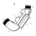
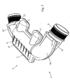
Figures 1 and2 are perspective views, from two different angles, of a conduit or pipe with integrated acoustic or vibration attenuators according to the invention; -
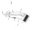
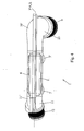
Figures 3 and4 are a lateral elevation and a rear view, respectively, of the conduit or pipe shown inFigures 1 and2 ; -
Figures 5 and6 are exploded perspective views showing the two constituent parts of the structure with a substantially flat constitution, formed by the multi-hole silencer/intermediate segment/quarter-wave attenuators assembly forming part of the conduit or pipe shown inFigures 1 to 4 , and -
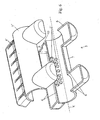
Figure 7 is an exploded perspective view showing the two constituent parts forming, by joining, the conduit or pipe shown inFigures 1 to 4 . -
Figures 1 to 4 and7 of the accompanying drawings show a conduit or pipe 1 for the circulation of gaseous fluid, in particular a gaseous mixture of various gaseous fluids, provided with an arrangement ofacoustic attenuators intermediate segment 4 of said conduit or pipe 1 and opening into the interior volume of saidsegment 4. - According to the invention, said arrangement of attenuators comprises a
multi-hole silencer 2 and two quarter-wave attenuators 3 and 3', said quarter-wave attenuators 3 and 3' being disposed so as to be acoustically coupled to saidsilencer 2. Saidintermediate segment 4 has a structure that is substantially rectilinear with a central circulation axis or median axis X, and themulti-hole silencer 2, on the one hand, and the two quarter-wave attenuators 3 and 3', on the other hand, are located either side of said median axis X of saidsegment 4, so as to form, together with thissilencer 2 and these twoattenuators 3 and 3', a single-piece structure 5 with a substantially flat configuration or constitution. - Preferably, as emerges, in particular, from
Figures 3 ,4 and5 of the accompanying drawings, themulti-hole silencer 2 and the two quarter-wave attenuators 3 and 3' have, viewed in lateral elevation in the median plane PM of thestructure 5 with a flat configuration, formed by themulti-hole silencer 2/intermediate segment 4/quarter-wave attenuators 3 and 3' assembly, or in a plane parallel to this median plane, a thickness or an exterior height at most substantially equal to the thickness or the exterior height of theintermediate segment 4, in the direction perpendicular to said median plane PM, said median plane PM containing the central circulation or median axis X of saidintermediate segment 4. - According to an advantageous practical construction variant of the invention, the
multi-hole silencer 2 consists of a caisson or similar closed hollow body, formed on the wall of theintermediate segment 4 and communicating with the interior volume thereof through a plurality of openings 2', and each of the two quarter-wave attenuators 3 and 3' consists of a hollow body in the form of a deformation towards the exterior, forming a cavity in the wall of theintermediate segment 4, the twoattenuators 3 and 3' having different dimensions, in particular different depths. - These openings 2' may, for example, be in the form of through-perforations provided in the wall portion, common with the
silencer 2, of theintermediate segment 4, and forming a wall portion contributing to the delimitation of the interior volume of said silencer. - As an alternative, not shown in the accompanying drawings, the openings 2' may also be in the form of through-perforations provided in a plate or the like, made of a metallic or rigid synthetic material, mounted in a cut-out of the wall portion, common with the
silencer 2, of theintermediate segment 4, the edges of said plate defining baffle structures with the edges of said cut-out. - The
multi-hole silencer 2 may, for example, have a parallelepiped, preferably rectangular, shape, and each of the quarter-wave attenuators 3 and 3' consist of a cylindrical cavity, with a circular or non-circular section. - The large opposite walls delimiting the sound-proofing caisson of the multi-hole silencer, in the form of a flattened parallelepiped, may advantageously be connected to the wall of the
intermediate segment 4 by reinforcing ribs 4', rigidifying their mutual connection. - The respective relative dispositions of the quarter-
wave attenuators 3 and 3' in relation to themulti-hole silencer 2, in the direction of fluid flow in thesegment 4, may be varied, as a function, in particular, of the desired attenuation profile. - The two
attenuators 3 and 3' may thus both be located upstream or downstream of saidsilencer 2, or alternatively, as shown in the accompanying figures, be located facing each other, either side of the apertures forming communication openings 2' between the internal volumes of saidsilencer 2 and saidintermediate segment 4. - In particular, if the conduit or pipe consists of a conduit 1 through which the gaseous flow emitted from a turbocompressor of an internal combustion engine passes, it may advantageously be provided that the shapes, the dimensions, the relative dispositions and the degree of acoustic coupling of the
multi-hole silencer 2 and the two quarter-wave attenuators 3 and 3' are defined in such a way that the arrangement ofacoustic attenuators - The specific definitions of the various components may be calculated using simulation software known to a person skilled in the art.
- The two quarter-
wave attenuators 3 and 3' allow attenuation to be reinforced in the region of the extreme values of the frequency range to be attenuated, and will consequently be configured and dimensioned with this object. - According to an example, shown in
Figures 5 and6 of the accompanying drawings, it may be provided that at least the assembly formed by saidintermediate segment 4 with themulti-hole silencer 2 and the two quarter-wave attenuators 3 and 3' is formed by joining two single-piece parts 7 and 7', in the region ofassembly zones 6 located in the median plane PM of the structure with aflat configuration 5 formed by the aforementioned assembly, containing the central circulation or median X axis of the intermediaterectilinear conduit segment 4, each of the single-piece parts 7, 7' being formed by wall portions of theintermediate segment 4, themulti-hole silencer 2 and two quarter-wave attenuators 3 and 3'. - According to this example, any conduit segments and/or additional fittings also forming part of the conduit or pipe 1 may be connected to the opposite ends of the
intermediate segment 4 by an appropriate joining technique, after production of thestructure 5. - According to the invention, shown in
Figure 7 of the accompanying drawings, the conduit or pipe 1 is formed by joining twoconstituent parts 8 and 8', each of a single piece, afirst part 8 comprising a firsttubular fitting 9, optionally a wall portion of a first conduit segment, first wall portions 7 of themulti-hole silencer 2/intermediate segment 4/quarter-wave attenuators 3 and 3' assembly, optionally a wall portion of athird conduit segment 11 and a secondtubular fitting 12, and a second part 8' comprising second wall portions 7' of themulti-hole silencer 2/intermediate segment 4/quarter-wave attenuators 3 and 3' assembly, which second wall portions 7' are complementary to the aforementioned first wall portions 7, and, optionally, wall portions 10', 11' complementary to the first and/or third conduit segment(s), theassembly zones 6 of these twoconstituent parts 8, 8' preferably being located, in the region of thestructure 5 with a flat configuration formed by the aforementioned assembly, in the median plane PM of this structure. - The first and/or the third conduit segment(s) 10 and 10', 11 and 11' may optionally be omitted, the corresponding fitting(s) 9, 12 then being directly contiguous to the intermediate segment 4 (variants not shown).
- Each of the constituent single-piece parts 7, 7'; 8, 8' is produced by injection-moulding of thermoplastic material(s), optionally filled or reinforced with fibres, and the joining of the two parts 7, 7'; 8, 8' in the region of their assembly zones consists in vibration welding.
- Advantageously, the openings 2' are provided in the common wall portion between the
segment 4 and thesilencer 2. - If, alternatively, the openings 2' are provided in a connected plate forming an insert, said plate forming part of the wall portion, common with the
silencer 2 and comprising the openings 2', of theintermediate segment 4 is mounted with locking in the corresponding receiving cut-out of this wall portion, in the region of a peripheral groove, and is held by compression between the two parts 7, 7'; 8, 8'. - The present invention also relates to a method of producing a gaseous fluid circulation conduit or pipe of the above-described type.
- This method is characterised in that it consists in separately producing, by injection moulding, two complementary
constituent parts 8 and 8', each of a single piece, i.e. afirst part 8 comprising a firsttubular fitting 9, optionally a wall portion of a first conduit segment, first wall portions 7 of themulti-hole silencer 2/intermediate segment 4/quarter-wave attenuators 3 and 3' assembly, optionally a wall portion of athird conduit segment 11 and a secondtubular fitting 12, and a second part 8' comprising second wall portions 7' of themulti-hole silencer 2/intermediate segment 4/quarter-wave attenuators 3 and 3' assembly, which second wall portions are complementary to the aforementioned first wall portions 7, and, optionally, wall portions 10', 11' complementary to the first and/or third conduit segment(s), and in joining the two complementaryconstituent parts 8 and 8' by vibration welding, in the region of assembly zones defined by the partition of the walls of the conduit or pipe, themulti-hole silencer 2 and the two quarter-wave attenuators 3 and 3'. - In an example, the two parts 7 and 7' may first be produced, then joined into a
single structure 5 and, finally, the additional (first and third) conduit segments and thefittings - According to an additional characteristic, the complementary wall portions forming, by cooperation and joining, the rectilinear
intermediate segment 4 of the conduit or pipe 1 each comprise a part, preferably half, of the through-openings 2' of themulti-hole silencer 2, these openings 2' being formed during the production of the correspondingconstituent part 8, 8', by demoulding in an inclined movement in relation to the principal demoulding axis formed by the direction, perpendicular to the imaginary plane containing theassembly zones 6, of the wall portions 7, 7' of thestructure 5 with a substantially flat configuration. - In a variant, the complementary wall portions forming, by cooperation and joining, the rectilinear
intermediate segment 4 may each comprise, in the region of their parts forming, by cooperation, a wall portion common with themulti-hole silencer 2, a cut-out part, these two cut-out parts forming by cooperation, at the moment when the twoconstituent parts 8 and 8' are joined, a receiving cut-out for a plate or the like comprising openings 2', this plate being mounted in one of saidparts 8, 8' prior to assembly and held after assembly in a peripheral groove of the receiving cut-out, by being locked by compression.
Claims (15)
- Gaseous fluid circulation conduit or pipe (1) having opposed first and second tubular fittings (9, 12), provided with an arrangement of acoustic attenuators (2, 3, 3'), extending laterally in the region of an intermediate segment (4) of said conduit or pipe and opening into the interior volume of said segment,
said arrangement comprising a multi-hole silencer (2) and two other attenuators (3 and 3'),
said other attenuators (3 and 3') being disposed so as to be acoustically coupled to said silencer (2), and said intermediate segment (4) has a structure substantially rectilinear with a central circulation axis or median axis (X),
the conduit or pipe (1) being characterised in that the two attenuators (3 and 3') are quarter-wave attenuators, in that the multi-hole silencer (2), on the one hand, and the two quarter-wave attenuators (3 and 3'), on the other hand, are located either side of said median axis (X) of said segment (4), so as to form, together with this silencer (2) and these two attenuators (3 and 3'), a single-piece structure (5) with a substantially flat configuration or constitution and
in that said structure (5) is made of two complementary constituent single-piece parts (8, 8*), each obtained by injection moulding of thermoplastic material(s) and both joined together by vibration welding, one of said parts (8, 8') also comprising at least said first and second tubular fittings (9, 12). - Conduit according to claim 1, characterised in that the multi-hole silencer (2) and the two quarter-wave attenuators (3 and 3') have, viewed in lateral elevation in the median plane (PM) of the structure (5) with a flat configuration, formed by the multi-hole silencer (2)/intermediate segment (4)/quarter-wave attenuators (3 and 3') assembly, or in a plane parallel to this median plane, a thickness or an exterior height at most substantially equal to the thickness or the exterior height of the intermediate segment (4), in the direction perpendicular to said median plane (PM), said median plane (PM) containing the central circulation or median axis (X) of said intermediate segment (4).
- Conduit according to any one of claims 1 and 2, characterised in that the multi-hole silencer (2) consists of a caisson or similar closed hollow body, formed on the wall of the intermediate segment (4) and communicating with the interior volume thereof through a plurality of through-openings (2') provided in said wall, and in that each of the two quarter-wave attenuators (3 and 3') consists of a hollow body in the form of a deformation towards the exterior, forming a cavity in the wall of the intermediate segment (4), the two attenuators (3 and 3') having different dimensions, in particular different depths.
- Conduit according to claim 3, characterised in that the openings (2') are in the form of through-perforations provided in the wall portion, common with the silencer (2), of the intermediate segment (4), and forming a wall portion contributing to the delimitation of the interior volume of said silencer.
- Conduit according to claim 3, characterised in that the openings (2') are in the form of through-perforations provided in a plate or the like, made of a metallic or rigid synthetic material, mounted in a cut-out of the wall portion, common with the silencer (2), of the intermediate segment (4), the edges of said plate defining baffle structures with the edges of said cut-out.
- Conduit according to any one of claims 3 to 5, characterised in that the multi-hole silencer (2) has a parallelepiped, preferably rectangular, shape, and in that each of the quarter-wave attenuators (3 and 3') consists of a cylindrical cavity, with a circular or non-circular section.
- Conduit according to any one of claims 1 to 6, characterised in that the shapes, the dimensions, the relative dispositions and the degree of acoustic coupling of the multi-hole silencer (2) and the two quarter-wave attenuators (3 and 3') are defined in such a way that the arrangement of acoustic attenuators (2, 3, 3') has an attenuation of at least 20 dB in the 1,500 Hz to 3,200 Hz frequency range.
- Conduit according to any one of claims 1 to 7, characterised in that at least the assembly formed by said intermediate segment (4) with the multi-hole silencer (2) and the two quarter-wave attenuators (3 and 3') is formed by joining two single-piece parts (7 and 7'), in the region of assembly zones (6) located in the median plane (PM) of the structure with a flat configuration (5) formed by the aforementioned assembly, containing the central circulation or median (X) axis of the intermediate rectilinear conduit segment (4), each of the single-piece parts (7, 7') being formed by wall portions of the intermediate segment (4), the multi-hole silencer (2) and two quarter-wave attenuators (3 and 3').
- Conduit according to any one of claims 1 to 8, characterised in that it is formed by joining two constituent parts (8 and 8'), each of a single piece, in that a first part (8) comprises a first tubular fitting (9), optionally a wall portion of a first conduit segment, first wall portions (7) of the multi-hole silencer (2)/intermediate segment (4)/quarter-wave attenuators (3 and 3') assembly, optionally a wall portion of a third conduit segment (11) and a second tubular fitting (12), and in that a second part (8') comprises second wall portions (7') of the multi-hole silencer (2)/intermediate segment (4)/quarter-wave attenuators (3 and 3') assembly, which second wall portions (7') are complementary to the aforementioned first wall portions (7), and, optionally, wall potions (10', 11') complementary to the first and/or third conduit segment(s), the assembly zones (6) of these two constituent parts (8, 8') preferably being located, in the region of the structure (5) with a flat configuration formed by the aforementioned assembly, in the median plane (PM) of this structure.
- Conduit according to any one of claims 8 and 9, in so far as it relates to claim 5, characterised in that the plate forming part of the wall portion, common with the silencer (2) and comprising the openings (2'), of the intermediate segment (4) is mounted with locking in the corresponding receiving cut-out of this wall portion, in the region of a peripheral groove, and is held by compression between the two parts (7, 7'; 8, 8').
- Conduit according to any one of claims 1 to 10, characterised in that it consists of a conduit (1) through which the gaseous flow emitted from a turbocompressor of an internal combustion engine passes.
- Method of producing a gaseous fluid circulation conduit or pipe according to any one of claims 1 to 11, consisting in separately producing, by injection moulding, two complementary constituent parts (8 and 8'), each of a single piece,
the method being characterised in that a first part (8) comprises a first tubular fitting (9), optionally a wall portion of a first conduit segment, first wall portions (7) of the multi-hole silencer (2)/intermediate segment (4)/quarter-wave attenuators (3 and 3') assembly, optionally a wall portion of a third conduit segment (11) and a second tubular fitting (12), and in that a second part (8') comprises second wall portions (7') of the multi-hole silencer (2)/intermediate segment (4)/quarter-wave attenuators (3 and 3') assembly, which second wall portions are complementary to the aforementioned first wall portions (7), and, optionally, wall portions (10', 11') complementary to the first and/or third conduit segment(s), and in that the two complementary constituent parts (8 and 8') are joined together by vibration welding, in the region of assembly zones defined by the partition of the walls of the conduit or pipe, the multi-hole silencer (2) and the two quarter-wave attenuators (3 and 3'), so as to obtain a single-piece structure (5) with a substantially flat configuration or constitution. - Production method according to claim 12, characterised in that the complementary wall portions forming, by cooperation and joining, the rectilinear intermediate segment (4) of the conduit or pipe (1) each comprise a part, preferably half, of the through-openings (2') of the multi-hole silencer (2), these openings (2') being formed during the production of the corresponding constituent part (8, 8'), by demoulding in an inclined movement in relation to the principal demoulding axis formed by the direction, perpendicular to the imaginary plane containing the assembly zones (6) of the wall portions (7, 7') of the structure (5) with a substantially flat configuration.
- Production method according to claim 12, characterised in that the complementary wall portions forming, by cooperation and joining, the rectilinear intermediate segment (4) each comprise, in the region of their parts forming, by cooperation, a wall portion common with the multi-hole silencer (2), a cut-out part, these two cut-out parts forming by cooperation, at the moment when the two constituent parts (8 and 8') are joined, a receiving cut-out for a plate or the like comprising openings (2'), this plate being mounted in one of said parts (8, 8') prior to assembly and held after assembly in a peripheral groove of the receiving cut-out, by being locked by compression.
- Production method according to any one of claims 12 to 14, characterised in that the two constituent parts (8 and 8') comprise, in the region of the assembly zones, complementary indexing cut-outs (13), allowing precise relative positioning of said two parts in relation to each other, before they are joined by vibration welding.
Applications Claiming Priority (2)
| Application Number | Priority Date | Filing Date | Title |
|---|---|---|---|
| FR0315280A FR2864199B1 (en) | 2003-12-23 | 2003-12-23 | INTEGRATED ACOUSTICAL ATTENUATOR CONDUIT AND ITS MANUFACTURING METHOD |
| FR0315280 | 2003-12-23 |
Publications (2)
| Publication Number | Publication Date |
|---|---|
| EP1548701A1 EP1548701A1 (en) | 2005-06-29 |
| EP1548701B1 true EP1548701B1 (en) | 2015-12-16 |
Family
ID=34531339
Family Applications (1)
| Application Number | Title | Priority Date | Filing Date |
|---|---|---|---|
| EP04106752.1A Expired - Lifetime EP1548701B1 (en) | 2003-12-23 | 2004-12-20 | Conduit with integrated acoustic attenuators and method for the production thereof |
Country Status (2)
| Country | Link |
|---|---|
| EP (1) | EP1548701B1 (en) |
| FR (1) | FR2864199B1 (en) |
Families Citing this family (10)
| Publication number | Priority date | Publication date | Assignee | Title |
|---|---|---|---|---|
| US7526094B2 (en) * | 2003-03-25 | 2009-04-28 | Robert Hickling | Normalization and calibration of microphones in sound-intensity probes |
| DE102005052619B4 (en) * | 2005-11-02 | 2012-10-18 | J. Eberspächer GmbH & Co. KG | Silencer for an exhaust system |
| FR2894645B1 (en) * | 2005-12-13 | 2009-03-20 | Coutier Moulage Gen Ind | GAS TRANSPORT DUCT HAVING A VARIABLE PRESSURE FLOW WITH INTEGRATED ACOUSTICAL ATTENUATION |
| US9452840B2 (en) * | 2014-04-15 | 2016-09-27 | The Boeing Company | Monolithic part and method of forming the monolithic part |
| JP6169035B2 (en) * | 2014-04-22 | 2017-07-26 | 小島プレス工業株式会社 | Silencer structure for exhaust noise of fuel cell vehicles |
| FR3027995B1 (en) | 2014-11-05 | 2018-06-15 | Systemes Moteurs | DUCT INTEGRATING AN ACOUSTICAL ATTENUATION DEVICE |
| CN105587373B (en) * | 2015-03-31 | 2018-11-23 | 徐工集团工程机械股份有限公司 | A kind of silencing apparatus and vehicle motor |
| DE102015211460A1 (en) * | 2015-06-22 | 2016-12-22 | Bayerische Motoren Werke Aktiengesellschaft | exhaust system |
| CN115050347B (en) * | 2022-07-12 | 2025-06-03 | 合肥美的电冰箱有限公司 | Muffler |
| CN116698393B (en) * | 2023-08-08 | 2023-11-14 | 江苏垒博汽配制造有限公司 | Assembly detection tool and detection method for sound dissipater and silencer shell |
Family Cites Families (7)
| Publication number | Priority date | Publication date | Assignee | Title |
|---|---|---|---|---|
| JPS5815708A (en) * | 1981-07-22 | 1983-01-29 | Nissan Motor Co Ltd | Muffler |
| US5252788A (en) * | 1992-04-10 | 1993-10-12 | Ap Parts Manufacturing Co. | Stamp formed muffler with in-line expansion chamber and arcuately formed effective flow tubes |
| JP3443140B2 (en) * | 1993-10-04 | 2003-09-02 | 富士重工業株式会社 | Multilayer plastic molded article and method for producing the same |
| JPH09144986A (en) * | 1995-11-27 | 1997-06-03 | Nissan Motor Co Ltd | Sound absorbing duct structure |
| DE29607010U1 (en) * | 1996-04-18 | 1997-08-14 | Heinrich Gillet Gmbh & Co Kg, 67480 Edenkoben | Silencer |
| US6679215B2 (en) * | 2001-11-30 | 2004-01-20 | Delphi Technologies, Inc. | Injection-molded air intake manifold for a V-style engine |
| FR2840847B1 (en) * | 2002-06-13 | 2004-10-22 | Mark Iv Systemes Moteurs Sa | METHOD FOR MANUFACTURING A PIPE PROVIDED WITH AT LEAST ONE ATTENUATOR AND RESULTING PIPE |
-
2003
- 2003-12-23 FR FR0315280A patent/FR2864199B1/en not_active Expired - Lifetime
-
2004
- 2004-12-20 EP EP04106752.1A patent/EP1548701B1/en not_active Expired - Lifetime
Also Published As
| Publication number | Publication date |
|---|---|
| EP1548701A1 (en) | 2005-06-29 |
| FR2864199B1 (en) | 2006-02-24 |
| FR2864199A1 (en) | 2005-06-24 |
Similar Documents
| Publication | Publication Date | Title |
|---|---|---|
| JPH088305Y2 (en) | Silencer | |
| EP0859906B2 (en) | A noise attenuator for an induction system or an exhaust system | |
| EP1548701B1 (en) | Conduit with integrated acoustic attenuators and method for the production thereof | |
| JP2006046327A (en) | Intake noise attenuator | |
| KR20010042404A (en) | Suction Duct | |
| US6205968B1 (en) | Induction system, especially for use as an induction port of an internal combustion engine | |
| EP2317115A2 (en) | Intake manifold with integrated sound barrier | |
| EP1975380B1 (en) | Muffler structure for vehicle | |
| CN207093249U (en) | Compound air inlet resonant cavity and automobile | |
| CN104602933A (en) | vehicle door structure | |
| US20040262076A1 (en) | Fluid guideline, especially in the form of a tube for taking up untreated air in an air filter of a motor vehicle | |
| JP3653763B2 (en) | Silencer | |
| US20070068589A1 (en) | Intake duct | |
| EP0897060A2 (en) | Intake silencer system | |
| US20030221651A1 (en) | Air intake system for engine | |
| US6092499A (en) | Intake pipe | |
| JP6808697B2 (en) | Silent members, how to make sound-insulated bodies and cars | |
| WO2002027166A1 (en) | Reduced-noise device | |
| WO1998049440A1 (en) | Integrated duct and resonator for an automobile engine air induction system | |
| US10443550B2 (en) | Intake manifold with impressions for improved NVH performance | |
| JP3894619B2 (en) | Synthetic resin intake manifold for internal combustion engines | |
| JP3346084B2 (en) | Sound absorbing device | |
| JP3019838B2 (en) | Tank with divider | |
| JPH1115476A (en) | Ventilated sound insulation wall structure | |
| CN110792536B (en) | Air intake system component |
Legal Events
| Date | Code | Title | Description |
|---|---|---|---|
| PUAI | Public reference made under article 153(3) epc to a published international application that has entered the european phase |
Free format text: ORIGINAL CODE: 0009012 |
|
| AK | Designated contracting states |
Kind code of ref document: A1 Designated state(s): AT BE BG CH CY CZ DE DK EE ES FI FR GB GR HU IE IS IT LI LT LU MC NL PL PT RO SE SI SK TR |
|
| AX | Request for extension of the european patent |
Extension state: AL BA HR LV MK YU |
|
| 17P | Request for examination filed |
Effective date: 20051221 |
|
| AKX | Designation fees paid |
Designated state(s): AT BE BG CH CY CZ DE DK EE ES FI FR GB GR HU IE IS IT LI LT LU MC NL PL PT RO SE SI SK TR |
|
| 17Q | First examination report despatched |
Effective date: 20120330 |
|
| GRAP | Despatch of communication of intention to grant a patent |
Free format text: ORIGINAL CODE: EPIDOSNIGR1 |
|
| RIC1 | Information provided on ipc code assigned before grant |
Ipc: F01N 1/00 20060101ALI20150622BHEP Ipc: F01N 13/18 20100101ALI20150622BHEP Ipc: G10K 11/172 20060101AFI20150622BHEP |
|
| INTG | Intention to grant announced |
Effective date: 20150706 |
|
| GRAS | Grant fee paid |
Free format text: ORIGINAL CODE: EPIDOSNIGR3 |
|
| GRAA | (expected) grant |
Free format text: ORIGINAL CODE: 0009210 |
|
| RAP1 | Party data changed (applicant data changed or rights of an application transferred) |
Owner name: SYSTEMES MOTEURS |
|
| AK | Designated contracting states |
Kind code of ref document: B1 Designated state(s): AT BE BG CH CY CZ DE DK EE ES FI FR GB GR HU IE IS IT LI LT LU MC NL PL PT RO SE SI SK TR |
|
| REG | Reference to a national code |
Ref country code: GB Ref legal event code: FG4D |
|
| REG | Reference to a national code |
Ref country code: CH Ref legal event code: EP |
|
| REG | Reference to a national code |
Ref country code: IE Ref legal event code: FG4D |
|
| REG | Reference to a national code |
Ref country code: AT Ref legal event code: REF Ref document number: 765883 Country of ref document: AT Kind code of ref document: T Effective date: 20160115 |
|
| REG | Reference to a national code |
Ref country code: FR Ref legal event code: PLFP Year of fee payment: 12 |
|
| REG | Reference to a national code |
Ref country code: DE Ref legal event code: R096 Ref document number: 602004048369 Country of ref document: DE |
|
| REG | Reference to a national code |
Ref country code: NL Ref legal event code: MP Effective date: 20151216 |
|
| REG | Reference to a national code |
Ref country code: LT Ref legal event code: MG4D |
|
| PG25 | Lapsed in a contracting state [announced via postgrant information from national office to epo] |
Ref country code: LT Free format text: LAPSE BECAUSE OF FAILURE TO SUBMIT A TRANSLATION OF THE DESCRIPTION OR TO PAY THE FEE WITHIN THE PRESCRIBED TIME-LIMIT Effective date: 20151216 |
|
| REG | Reference to a national code |
Ref country code: AT Ref legal event code: MK05 Ref document number: 765883 Country of ref document: AT Kind code of ref document: T Effective date: 20151216 |
|
| PG25 | Lapsed in a contracting state [announced via postgrant information from national office to epo] |
Ref country code: BE Free format text: LAPSE BECAUSE OF NON-PAYMENT OF DUE FEES Effective date: 20151231 Ref country code: NL Free format text: LAPSE BECAUSE OF FAILURE TO SUBMIT A TRANSLATION OF THE DESCRIPTION OR TO PAY THE FEE WITHIN THE PRESCRIBED TIME-LIMIT Effective date: 20151216 Ref country code: FI Free format text: LAPSE BECAUSE OF FAILURE TO SUBMIT A TRANSLATION OF THE DESCRIPTION OR TO PAY THE FEE WITHIN THE PRESCRIBED TIME-LIMIT Effective date: 20151216 Ref country code: SE Free format text: LAPSE BECAUSE OF FAILURE TO SUBMIT A TRANSLATION OF THE DESCRIPTION OR TO PAY THE FEE WITHIN THE PRESCRIBED TIME-LIMIT Effective date: 20151216 Ref country code: GR Free format text: LAPSE BECAUSE OF FAILURE TO SUBMIT A TRANSLATION OF THE DESCRIPTION OR TO PAY THE FEE WITHIN THE PRESCRIBED TIME-LIMIT Effective date: 20160317 |
|
| PG25 | Lapsed in a contracting state [announced via postgrant information from national office to epo] |
Ref country code: CZ Free format text: LAPSE BECAUSE OF FAILURE TO SUBMIT A TRANSLATION OF THE DESCRIPTION OR TO PAY THE FEE WITHIN THE PRESCRIBED TIME-LIMIT Effective date: 20151216 Ref country code: IT Free format text: LAPSE BECAUSE OF FAILURE TO SUBMIT A TRANSLATION OF THE DESCRIPTION OR TO PAY THE FEE WITHIN THE PRESCRIBED TIME-LIMIT Effective date: 20151216 Ref country code: ES Free format text: LAPSE BECAUSE OF FAILURE TO SUBMIT A TRANSLATION OF THE DESCRIPTION OR TO PAY THE FEE WITHIN THE PRESCRIBED TIME-LIMIT Effective date: 20151216 |
|
| REG | Reference to a national code |
Ref country code: CH Ref legal event code: PL |
|
| PG25 | Lapsed in a contracting state [announced via postgrant information from national office to epo] |
Ref country code: IS Free format text: LAPSE BECAUSE OF FAILURE TO SUBMIT A TRANSLATION OF THE DESCRIPTION OR TO PAY THE FEE WITHIN THE PRESCRIBED TIME-LIMIT Effective date: 20160416 Ref country code: EE Free format text: LAPSE BECAUSE OF FAILURE TO SUBMIT A TRANSLATION OF THE DESCRIPTION OR TO PAY THE FEE WITHIN THE PRESCRIBED TIME-LIMIT Effective date: 20151216 Ref country code: PT Free format text: LAPSE BECAUSE OF FAILURE TO SUBMIT A TRANSLATION OF THE DESCRIPTION OR TO PAY THE FEE WITHIN THE PRESCRIBED TIME-LIMIT Effective date: 20160418 Ref country code: SK Free format text: LAPSE BECAUSE OF FAILURE TO SUBMIT A TRANSLATION OF THE DESCRIPTION OR TO PAY THE FEE WITHIN THE PRESCRIBED TIME-LIMIT Effective date: 20151216 Ref country code: RO Free format text: LAPSE BECAUSE OF FAILURE TO SUBMIT A TRANSLATION OF THE DESCRIPTION OR TO PAY THE FEE WITHIN THE PRESCRIBED TIME-LIMIT Effective date: 20151216 Ref country code: AT Free format text: LAPSE BECAUSE OF FAILURE TO SUBMIT A TRANSLATION OF THE DESCRIPTION OR TO PAY THE FEE WITHIN THE PRESCRIBED TIME-LIMIT Effective date: 20151216 |
|
| REG | Reference to a national code |
Ref country code: DE Ref legal event code: R097 Ref document number: 602004048369 Country of ref document: DE |
|
| REG | Reference to a national code |
Ref country code: IE Ref legal event code: MM4A |
|
| PG25 | Lapsed in a contracting state [announced via postgrant information from national office to epo] |
Ref country code: MC Free format text: LAPSE BECAUSE OF FAILURE TO SUBMIT A TRANSLATION OF THE DESCRIPTION OR TO PAY THE FEE WITHIN THE PRESCRIBED TIME-LIMIT Effective date: 20151216 |
|
| PLBE | No opposition filed within time limit |
Free format text: ORIGINAL CODE: 0009261 |
|
| STAA | Information on the status of an ep patent application or granted ep patent |
Free format text: STATUS: NO OPPOSITION FILED WITHIN TIME LIMIT |
|
| PG25 | Lapsed in a contracting state [announced via postgrant information from national office to epo] |
Ref country code: CH Free format text: LAPSE BECAUSE OF NON-PAYMENT OF DUE FEES Effective date: 20151231 Ref country code: DK Free format text: LAPSE BECAUSE OF FAILURE TO SUBMIT A TRANSLATION OF THE DESCRIPTION OR TO PAY THE FEE WITHIN THE PRESCRIBED TIME-LIMIT Effective date: 20151216 Ref country code: IE Free format text: LAPSE BECAUSE OF NON-PAYMENT OF DUE FEES Effective date: 20151220 Ref country code: PL Free format text: LAPSE BECAUSE OF FAILURE TO SUBMIT A TRANSLATION OF THE DESCRIPTION OR TO PAY THE FEE WITHIN THE PRESCRIBED TIME-LIMIT Effective date: 20151216 Ref country code: LI Free format text: LAPSE BECAUSE OF NON-PAYMENT OF DUE FEES Effective date: 20151231 |
|
| REG | Reference to a national code |
Ref country code: FR Ref legal event code: PLFP Year of fee payment: 13 |
|
| 26N | No opposition filed |
Effective date: 20160919 |
|
| GBPC | Gb: european patent ceased through non-payment of renewal fee |
Effective date: 20160316 |
|
| PG25 | Lapsed in a contracting state [announced via postgrant information from national office to epo] |
Ref country code: BE Free format text: LAPSE BECAUSE OF FAILURE TO SUBMIT A TRANSLATION OF THE DESCRIPTION OR TO PAY THE FEE WITHIN THE PRESCRIBED TIME-LIMIT Effective date: 20151216 |
|
| PG25 | Lapsed in a contracting state [announced via postgrant information from national office to epo] |
Ref country code: GB Free format text: LAPSE BECAUSE OF NON-PAYMENT OF DUE FEES Effective date: 20160316 |
|
| PG25 | Lapsed in a contracting state [announced via postgrant information from national office to epo] |
Ref country code: SI Free format text: LAPSE BECAUSE OF FAILURE TO SUBMIT A TRANSLATION OF THE DESCRIPTION OR TO PAY THE FEE WITHIN THE PRESCRIBED TIME-LIMIT Effective date: 20151216 |
|
| PG25 | Lapsed in a contracting state [announced via postgrant information from national office to epo] |
Ref country code: HU Free format text: LAPSE BECAUSE OF FAILURE TO SUBMIT A TRANSLATION OF THE DESCRIPTION OR TO PAY THE FEE WITHIN THE PRESCRIBED TIME-LIMIT; INVALID AB INITIO Effective date: 20041220 Ref country code: BG Free format text: LAPSE BECAUSE OF FAILURE TO SUBMIT A TRANSLATION OF THE DESCRIPTION OR TO PAY THE FEE WITHIN THE PRESCRIBED TIME-LIMIT Effective date: 20151216 |
|
| PG25 | Lapsed in a contracting state [announced via postgrant information from national office to epo] |
Ref country code: CY Free format text: LAPSE BECAUSE OF FAILURE TO SUBMIT A TRANSLATION OF THE DESCRIPTION OR TO PAY THE FEE WITHIN THE PRESCRIBED TIME-LIMIT Effective date: 20151216 |
|
| PG25 | Lapsed in a contracting state [announced via postgrant information from national office to epo] |
Ref country code: TR Free format text: LAPSE BECAUSE OF FAILURE TO SUBMIT A TRANSLATION OF THE DESCRIPTION OR TO PAY THE FEE WITHIN THE PRESCRIBED TIME-LIMIT Effective date: 20151216 |
|
| REG | Reference to a national code |
Ref country code: FR Ref legal event code: PLFP Year of fee payment: 14 |
|
| PG25 | Lapsed in a contracting state [announced via postgrant information from national office to epo] |
Ref country code: LU Free format text: LAPSE BECAUSE OF NON-PAYMENT OF DUE FEES Effective date: 20151220 |
|
| PGFP | Annual fee paid to national office [announced via postgrant information from national office to epo] |
Ref country code: FR Payment date: 20231122 Year of fee payment: 20 Ref country code: DE Payment date: 20231121 Year of fee payment: 20 |
|
| REG | Reference to a national code |
Ref country code: DE Ref legal event code: R071 Ref document number: 602004048369 Country of ref document: DE |