EP1548520B1 - Tonerpatronensystem mit einmaliger Ladung und Durchführungsverfahren - Google Patents
Tonerpatronensystem mit einmaliger Ladung und Durchführungsverfahren Download PDFInfo
- Publication number
- EP1548520B1 EP1548520B1 EP04300947A EP04300947A EP1548520B1 EP 1548520 B1 EP1548520 B1 EP 1548520B1 EP 04300947 A EP04300947 A EP 04300947A EP 04300947 A EP04300947 A EP 04300947A EP 1548520 B1 EP1548520 B1 EP 1548520B1
- Authority
- EP
- European Patent Office
- Prior art keywords
- cartridge
- refill
- container
- toner
- chassis
- Prior art date
- Legal status (The legal status is an assumption and is not a legal conclusion. Google has not performed a legal analysis and makes no representation as to the accuracy of the status listed.)
- Expired - Lifetime
Links
Images
Classifications
-
- G—PHYSICS
- G03—PHOTOGRAPHY; CINEMATOGRAPHY; ANALOGOUS TECHNIQUES USING WAVES OTHER THAN OPTICAL WAVES; ELECTROGRAPHY; HOLOGRAPHY
- G03G—ELECTROGRAPHY; ELECTROPHOTOGRAPHY; MAGNETOGRAPHY
- G03G15/00—Apparatus for electrographic processes using a charge pattern
- G03G15/06—Apparatus for electrographic processes using a charge pattern for developing
- G03G15/08—Apparatus for electrographic processes using a charge pattern for developing using a solid developer, e.g. powder developer
- G03G15/0822—Arrangements for preparing, mixing, supplying or dispensing developer
- G03G15/0848—Arrangements for testing or measuring developer properties or quality, e.g. charge, size, flowability
- G03G15/0849—Detection or control means for the developer concentration
- G03G15/0855—Detection or control means for the developer concentration the concentration being measured by optical means
-
- G—PHYSICS
- G03—PHOTOGRAPHY; CINEMATOGRAPHY; ANALOGOUS TECHNIQUES USING WAVES OTHER THAN OPTICAL WAVES; ELECTROGRAPHY; HOLOGRAPHY
- G03G—ELECTROGRAPHY; ELECTROPHOTOGRAPHY; MAGNETOGRAPHY
- G03G15/00—Apparatus for electrographic processes using a charge pattern
- G03G15/06—Apparatus for electrographic processes using a charge pattern for developing
- G03G15/08—Apparatus for electrographic processes using a charge pattern for developing using a solid developer, e.g. powder developer
- G03G15/0822—Arrangements for preparing, mixing, supplying or dispensing developer
- G03G15/0865—Arrangements for supplying new developer
- G03G15/0875—Arrangements for supplying new developer cartridges having a box like shape
-
- G—PHYSICS
- G03—PHOTOGRAPHY; CINEMATOGRAPHY; ANALOGOUS TECHNIQUES USING WAVES OTHER THAN OPTICAL WAVES; ELECTROGRAPHY; HOLOGRAPHY
- G03G—ELECTROGRAPHY; ELECTROPHOTOGRAPHY; MAGNETOGRAPHY
- G03G15/00—Apparatus for electrographic processes using a charge pattern
- G03G15/06—Apparatus for electrographic processes using a charge pattern for developing
- G03G15/08—Apparatus for electrographic processes using a charge pattern for developing using a solid developer, e.g. powder developer
- G03G15/0894—Reconditioning of the developer unit, i.e. reusing or recycling parts of the unit, e.g. resealing of the unit before refilling with toner
-
- G—PHYSICS
- G03—PHOTOGRAPHY; CINEMATOGRAPHY; ANALOGOUS TECHNIQUES USING WAVES OTHER THAN OPTICAL WAVES; ELECTROGRAPHY; HOLOGRAPHY
- G03G—ELECTROGRAPHY; ELECTROPHOTOGRAPHY; MAGNETOGRAPHY
- G03G2215/00—Apparatus for electrophotographic processes
- G03G2215/06—Developing structures, details
- G03G2215/066—Toner cartridge or other attachable and detachable container for supplying developer material to replace the used material
- G03G2215/0663—Toner cartridge or other attachable and detachable container for supplying developer material to replace the used material having a longitudinal rotational axis, around which at least one part is rotated when mounting or using the cartridge
- G03G2215/0665—Generally horizontally mounting of said toner cartridge parallel to its longitudinal rotational axis
Definitions
- the invention relates to a single-refill toner cartridge system for use in a printer or facsimile type printing device.
- This cartridge system includes a toner cartridge which, when empty, can be refilled once with a refill adapted to that cartridge.
- the invention also relates to a method for implementing this system.
- the invention has applications in the field of digital printing. It finds, in particular, applications in the field of printing by computer devices such as printers, photocopiers or fax machines.
- this toner is placed in a cartridge inside the machine.
- Each toner cartridge is intended for a limited number of printed pages, for example 3000 or 5000 pages.
- the cartridge is empty, there are two possibilities for the user of the device: either he replaces the empty cartridge with a new full cartridge, or he refills the cartridge with bottled toner.
- the change of a cartridge has the disadvantage of having a relatively high cost. Indeed, an entire cartridge has a significantly higher cost than bottled toner. Also, most users choose to fill the cartridge with toner sold in bottles. In this case, to fill the cartridge, the user must open the cartridge, open the toner bottle and directly pour the toner into the cartridge. Toner is a fine powder that flakes easily, especially when is transferred from one container to another container. In addition, this fine powder is colored. It therefore dirty the elements around the cartridge to be filled and the hands and clothes of the user. In addition, opening the cap of the cartridge also causes dirt on the user's hands and inhalations of toner vapor that can affect the health of the user. the opening of the plug can, in addition, deteriorate the plug. This technique is therefore not only messy, but in addition it is relatively long to implement.
- this technique does not make it possible to control the life of the components of the cartridge and, in particular, the rollers of the cartridge which can become dirty and deteriorate the quality of the printing, or even make the printing device unusable.
- tongues are relatively fragile and it is common that they break when the user pulls to open the refill. The user is then obliged to remove the refill from the cartridge, with all the disadvantages that entails, especially if the refill has been partially opened by the tab.
- the document US-A-5,907,747 describes another type of refill for a toner cartridge.
- This refill has a shape substantially identical to the shape of the cartridge and it is inserted into the receptacle of the cartridge. The lid of the cartridge is then attached to the top of the refill to seal the assembly. When the cartridge is closed, with the refill inside, the user must pull a tab to open the refill.
- This recharge therefore has the same disadvantages as those stated above.
- the invention proposes a single toner refill cartridge system comprising a full cartridge of toner and a refill to be inserted into the cartridge, in a simple and clean way, when the cartridge is empty.
- This refill cartridge system makes it possible to refill a toner cartridge without having to pull a tab or any other element that can be stamped with toner.
- the toner refill comprises a container inside which is initially the toner. This container is rotatable in the cartridge so that, in a closed position, the toner is contained within the container and, in an open position, the toner is evacuated to the cartridge receptacle. The passage from the closed position to the open position of the container is achieved simply by pressing the user on the container.
- This single-refill cartridge system allows the cartridge to be recharged cleanly without the user being in direct contact with the toner at any time. It also ensures complete recycling of the cartridge and refill assembly since, when the refill has been introduced into the cartridge, it can no longer be removed from the cartridge. Also, when the refill is empty, the user returns the cartridge and refill assembly to the manufacturer who then has at his disposal all the "dirty" elements requiring recycling.
- This system also has the advantage of allowing the manufacturer to control the life of the components and, in particular, their clogging by limiting the possible number of printed pages. In other words, if the manufacturer knows that the components have a life of 10000 pages, he adapts the amount of toner in the cartridge and the refill so that the number of pages does not exceed 10000.
- This system also has the advantage of being less expensive for the user than two cartridges, for an identical number of pages with a good print guarantee.
- the invention relates to a toner refill cartridge system according to claim 1.
- the invention also relates to a method of implementing the refill cartridge system according to claim 13.
- the system of the invention comprises a toner cartridge which, when empty, can be recharged by means of a suitable toner refill.
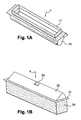
- the Figure 1A represents a perspective view of the cartridge of the system of the invention.
- This cartridge 1 comprises a receptacle 10 for receiving toner.
- This receptacle 10 is surmounted by a frame 11 fixed on the receptacle.
- a lid closes the cartridge.
- This cover is removably attached to the frame 11 of the cartridge 1. It is easily removable by the user. Indeed, this cover must be removed from the cartridge when a refill is put in place. That's why this lid is not represented on the Figure 1A .
- the Figure 1B represents a refill of the system of the invention.
- This recharge 2 of the Figure 1B is adapted to be inserted into the cartridge of the Figure 1A . It comprises a frame 20 and a rotating container 22 in the frame 20.
- the frame 20 of the refill 2 comprises a flange 21 forming a recess on the upper part of the frame. This flange 21 serves as a stop for the refill 2, when it is inserted into the cartridge 1.
- the container 22 is pivotally mounted about a longitudinal axis of rotation, fixed on the frame. An exemplary form of the container 22 will be described later.
- This container 22 may comprise a notch 23, made on the opposite side to the axis of rotation, to indicate to the user the location where the support must be to open the container.
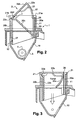
- the figure 2 is a sectional side view of the cartridge and refill system of the invention.
- This figure shows the cartridge 1 with its receptacle 10 at the bottom of which are one or more rollers 4 for spreading the toner output 5 of the receptacle 10. These rolls are identical to those of conventional printing devices.
- the receptacle 10 contains the toner. When the cartridge is new, this receptacle is initially filled with toner. When the cartridge is refilled, it is filled with the toner initially contained in the container. In other words, the toner contained in the container 22 of the refill is intended to be poured into the receptacle 10 of the cartridge 1.
- the receptacle 10 is surmounted by a frame 11 fixed to the receptacle by any known means, such as glue. It can also be overmoulded on the receptacle 10. Initially, when the cartridge is new, the frame 11 is closed by a cover placed and fixed on said frame 11. During the second use of the cartridge, that is to say when the cartridge is recharged, the lid is removed and it is the refill that bears on the frame 11.
- the figure 2 shows the preferred form for the container 22 of the refill 2.
- the container has a substantially triangular section.
- the container comprises three sides 22a, 22b and 22c.
- the side 22a forms the base of the triangle, opposite the top 22e.
- the sides 22b and 22c meet around the axis of rotation 3.
- the side 22c forms a circular arc 22d about the axis 3 to facilitate the rotation of the container in the cartridge.
- the container side 22b forms an angle of approximately 45 ° with the chassis surface; it is understood that this angle may vary, depending in particular on the shape of the container, while remaining less than 90 °.
- the base 22a is partly open, over the entire length of the refill. In other words, the base 22a does not completely close the container 22.
- the container 22 is closed by the frame 20 of the refill. So, as it will be seen in more detail later, the container 22 has a closed position, which is the one shown on the figure 2 , in which the toner is contained entirely in the container closed by the frame.
- An open position which will be described later, makes it possible to rotate the container around the axis 3 and thus to tilt said container so that the opening in the base 22a is facing the receptacle of the cartridge.
- the frame 20 of the refill 2 has vertical walls 20a and 20b which can be of different lengths.
- the walls 20a and 20b end at their upper end by a collar 21.
- This collar 21 may be uniform over the entire contour of the refill. It can also have different shapes depending on the considered faces of the refill.
- the flange 21 may form a right angle with the wall 20a of the frame, as shown by reference 21a. It can also form a half U with the wall 20b of the frame, as shown by reference 21 b. Whatever its shape, the flange 21 has the role of providing abutment against the frame of the cartridge. The refill can not be introduced too deeply into the cartridge by the user.
- the wall 20a of the frame may be covered with a sealing material 26, for example a foam, sealing the container when it is in the closed position.
- a sealing material 26 for example a foam
- This anti-dismounting device 12, 27, also called non-return, comprises at least one lug 12 located inside the receptacle 10 of the cartridge and at least one orifice 27 formed in the wall 20b of the frame 20 of the refill.
- the lug 12 is intended to fit into the orifice 27 so as to prevent disassembly of the refill once it has been inserted into the cartridge. Only one refill can be introduced into the cartridge. Once the refill toner has been fully used, it is mechanically impossible for the user to pop the refill out of the cartridge.
- the lug 12 is a rack, molded on the inner face of the receptacle and directed towards the bottom of the receptacle 10.
- the rack 12 is easily introduced into the orifice 27 when the refill is pushed towards the bottom of the receptacle.
- the rack 12 is in abutment against the portion of the wall 20b surrounding the orifice 27, which prevents the refill can be pulled up the cartridge.
- the container 22 has a shape whose section is substantially triangular.
- the base 22a of the container is convex which allows to increase the interior volume of the container. It is understood that other forms can be envisaged for the container, such as a straight base.
- top 22e of the container 22 is shown with a partially rounded half-U shape which is inserted into the collar 21 around the axis of rotation 3. It should be noted that the shape of the top 22d and the flange 21b may differ depending on the embodiments.
- FIG 3 schematically shows a sectional side view of the system of the invention, when the container of the refill is in the open position.
- the side 22b of the container 22 forms, with the surface of the flange 21, a flat angle.
- the 22c side of the container 22 is then parallel to the wall 20b of the frame.
- the base 22a is inside the chassis. The convex shape of the base 22a ensures a good flow of the toner to the receptacle 10, without any toner retention.
- the user To move from the closed position of the container 22, shown on the figure 2 , at the open position of the container, shown on the figure 3 , the user simply has to push on the side 22b of the container, preferably on the notch 23. This pressure has the effect of pivoting the container downwards, putting the open part of the base 22a facing the receptacle 10 of the cartridge. The toner then escapes from the container 22 according to the arrow represented on the figure 3 .
- the toner escapes over the entire length of the container. Thus, it is distributed homogeneously in the receptacle. There is no need, before positioning the refill in the cartridge, to shake the refill to distribute the toner. Indeed, the refill is usually full. Also, when it evacuates container, the toner is distributed homogeneously and evenly in the receptacle at the time of opening of the container.
- the container 22 In the open position, the container 22 is fully inserted into the cartridge and the outer shape of the cartridge is identical to the shape of a new cartridge.
- the cartridge can therefore be reused, by the user, exactly like a new cartridge.
- the refill cartridge system of the invention is clean since there is no contact with toner emanation when transferring it from the refill to the cartridge.
- the new cartridge may have a protective film sealed to the cartridge frame.
- this film is located under the cartridge cover.
- This protective film can be made of a plastic material, such as a very thin polycarbonate, or in aluminum.
- the protective film may also comprise reduced areas easy to pierce, so that, when it is put in place in the cartridge, the refill pierces the protective film at predetermined locations, for example in the center of the film. Once the film is pierced, the pieces of the film are distributed all around the refill so as not to hinder the evacuation of the toner.
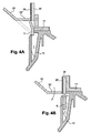
- this locking device comprises a deformable locking finger 6.
- This finger of locking 6 can be made in the same material as the refill, that is to say in ABS or PS.
- the container 22 forms a recess 22 '.
- the side 22c of the container is locally perpendicular to the foam 26, as shown by the reference 22 '.
- the dotted lines show the general shape of the container 22, out of proximity of the locking finger.
- the locking finger 6 is fixed and deforms as the refill passes through the receptacle of the cartridge. It can have two positions: an outer position in which it is partly outside the receptacle and an inner position in which it is entirely housed in the receptacle.
- the locking finger 6 has been shown when in its outer position, that is to say partly out of the receptacle of the cartridge. In this position, the locking finger has a curved shape which has the effect that the finger retains the side 22c of the container.
- the container can not open. As long as the refill is not correctly installed in the cartridge, the locking finger holds the container in its closed position. There is therefore no possible evacuation of the toner.
- the locking finger is pressed into a housing 7 of the receptacle.
- the container can then open.
- the cartridge can be reloaded without being removed from its location in the printing device. Indeed, since most of the printing device opens at the top, by a cover to open or part of the device to be removed, reloading the cartridge from above allows the reloading can be done in place in the device, without necessarily removing the cartridge from its housing.
- a user who orders a cartridge receives both a new cartridge and a refill.
- he uses the cartridge alone to make his impressions.
- the cartridge When the cartridge is empty of any toner, it can fill it with the refill. He must then remove the cover of the cartridge, easy to disassemble. Since there is no more toner in the cartridge, the lid is clean, especially if the cartridge has a protective film. The lid can be thrown into the trash without any difficulty.
- the user introduces the refill into the cartridge and pushes the refill until the frame comes to rest on the frame of the cartridge. At this time, the refill is in its correct position and the user can press the prominent part of the container thus passing the container from its closed position to its open position.
- the toner is then evacuated homogeneously as the container is opened in the receptacle of the cartridge.
- the user then only has to use the cartridge as a new cartridge.
- the dimensions of the refill are designed so that the refill fits into the cartridge and that it retains the same size as a new cartridge, the thickness of the rim of the frame then replacing the thickness of the lid of the new cartridge.
- This cartridge refill system has the advantage of being simple and quick to implement.
Landscapes
- Physics & Mathematics (AREA)
- General Physics & Mathematics (AREA)
- Life Sciences & Earth Sciences (AREA)
- Sustainable Development (AREA)
- Dry Development In Electrophotography (AREA)
Claims (14)
- Tonernachfüllungskassettensystem mit:- einer Kassette (1), die eine von einem Rahmen (11) überragte Aufnahme (10) umfasst,- einer Tonernachfüllung (2), die in die Aufnahme der Kassette einfügbar ist, und die einen den Toner enthaltenden Behälter (22) umfasst, und- einem Gestell (20), das in die Aufnahme der Kassette einfügbar ist, dadurch gekennzeichnet, dass- der Behälter eine zum Teil offene Basis (22a) über die Nachfüllungslänge umfasst,- der Behälter derart montiert ist, dass er um eine an dem Gestell gebundene Rotationsachse (3) schwenkt, sodass der Behälter eine geschlossene Stellung, in welcher der Toner in dem Behälter durch Verschluss der Öffnung in der Basis des genannten Behälters mittels des Gestells enthalten ist, und eine offene Stellung, in welcher die Öffnung in der Basis gegenüber der Aufnahme zum Ausleeren des Toners aus dem genannten Behälter in die Aufnahme der Kassette positioniert ist, aufweist.
- System nach Anspruch 1, dadurch gekennzeichnet, dass der Behälter einen im wesentlich dreieckigen Querschnitt mit einer um die Rotationsachse schwenkenden Spitze und mit einer zum Teil offenen Basis (22a) aufweist.
- System nach einem der Ansprüche 1 bis 2, dadurch gekennzeichnet, dass in der geschlossenen Stellung der Behälter eine Seite (22b) aufweist, die einen nicht-ebenen Winkel, kleiner als 90°, mit der Oberfläche des Gestells bildet.
- System nach einem der Ansprüche 1 bis 3, dadurch gekennzeichnet, dass in der offenen Stellung der Behälter eine Seite (22b) aufweist, die einen ebenen Winkel mit der Oberfläche des Gestells bildet.
- System nach einem der Ansprüche 2 bis 4, dadurch gekennzeichnet, dass in der geschlossen Stellung des Behälters der offene Teil der Basis (22a) durch eine Wand (20a) des Gestells (20) des Behälters geschlossen ist.
- System nach Anspruch 5, dadurch gekennzeichnet, dass mindestens die Wand (20a) des den Behälter schließenden Gestells mit einer Schicht aus einem Dichtungsmaterial verdeckt ist.
- System nach einem der Ansprüche 1 bis 6, dadurch gekennzeichnet, dass das Nachfüllungsgestell einen durch den Rahmen (11) der Kassette abgestützten Flansch (21) umfasst.
- System nach einem der Ansprüche 1 bis 7, dadurch gekennzeichnet, dass die Aufnahme (10) der Kassette eine abbausichere Vorrichtung für die Nachfüllung umfasst.
- System nach Anspruch 8, dadurch gekennzeichnet, dass die abbausichere Vorrichtung ein Haltestift (12) umfasst, und das Gestell der Nachfüllung mindestens eine Öffnung (27) umfasst, in welche der Haltestift einfügbar ist.
- System nach einem der Ansprüche 1 bis 9, dadurch gekennzeichnet, dass die Kassette einen Riegelfinger (6) umfasst, der den Behälter in der geschlossenen Stellung haltet, solange die Nachfüllung nicht korrekt in die Kassette eingefügt wird.
- System nach Anspruch 10, dadurch gekennzeichnet, dass der Riegelfinger aus einem verformbaren Material hergestellt wird.
- System nach einem der Ansprüche 1 bis 11, dadurch gekennzeichnet, dass die Kassette ein an der Rahmenfläche gebunden Schutzfilm umfasst.
- Verfahren zum Verwenden des Tonernachfüllungskassettensystems nach einem der Ansprüche 1 bis 12, dadurch gekennzeichnet, dass es die folgenden Schritte umfasst:- Entfernen eines Deckels von der Kassette,- Einfügen der Nachfüllung (2) in die Kassette (1), bis der Flansch (21) der Nachfüllung von dem Rahmen (11) der Kassette abgestützt wird,- Pressen eine Seite (22b) des Behälters der Nachfüllung, um den genannten Behälter von der geschlossenen Stellung in die offene Stellung umzuschalten.
- Verfahren nach Anspruch 13, dadurch gekennzeichnet, dass die Nachfüllung in die Kassette eingefügt wird, wenn es kein Toner mehr in der genannten Kassette gibt.
Applications Claiming Priority (2)
| Application Number | Priority Date | Filing Date | Title |
|---|---|---|---|
| FR0351183A FR2864263B1 (fr) | 2003-12-23 | 2003-12-23 | Systeme de cartouche de toner a recharge unique et procede de mise en oeuvre |
| FR0351183 | 2003-12-23 |
Publications (3)
| Publication Number | Publication Date |
|---|---|
| EP1548520A2 EP1548520A2 (de) | 2005-06-29 |
| EP1548520A3 EP1548520A3 (de) | 2010-09-15 |
| EP1548520B1 true EP1548520B1 (de) | 2012-02-22 |
Family
ID=34531406
Family Applications (1)
| Application Number | Title | Priority Date | Filing Date |
|---|---|---|---|
| EP04300947A Expired - Lifetime EP1548520B1 (de) | 2003-12-23 | 2004-12-23 | Tonerpatronensystem mit einmaliger Ladung und Durchführungsverfahren |
Country Status (4)
| Country | Link |
|---|---|
| EP (1) | EP1548520B1 (de) |
| AT (1) | ATE546761T1 (de) |
| ES (1) | ES2381044T3 (de) |
| FR (1) | FR2864263B1 (de) |
Family Cites Families (8)
| Publication number | Priority date | Publication date | Assignee | Title |
|---|---|---|---|---|
| US4307763A (en) * | 1979-11-29 | 1981-12-29 | International Business Machines Corporation | Toner container |
| DK418883A (da) * | 1982-09-21 | 1984-03-22 | Xerox Corp | Apparat til overfoering af partikelmateriale |
| US4523834A (en) * | 1984-01-09 | 1985-06-18 | Pitney Bowes Inc. | Dry toner replenishing apparatus |
| DE3641077A1 (de) * | 1986-12-02 | 1988-06-09 | Eisbein Develop | Tonerstation fuer ein kopiergeraet o.dgl. |
| EP0483440B1 (de) * | 1990-10-30 | 1994-06-01 | BULL HN INFORMATION SYSTEMS ITALIA S.p.A. | Tonerbehälter für die Elektrofotografie |
| JPH05289515A (ja) * | 1992-04-15 | 1993-11-05 | Konica Corp | 画像形成装置 |
| US5832343A (en) * | 1995-04-03 | 1998-11-03 | Canon Kabushiki Kaisha | Toner supply method, toner accommodation container, process cartridge and electrophotographic image forming apparatus |
| US5907747A (en) * | 1998-02-02 | 1999-05-25 | Ward Sealing, Inc. | Prefilled, presealed toner cartridge insert |
-
2003
- 2003-12-23 FR FR0351183A patent/FR2864263B1/fr not_active Expired - Fee Related
-
2004
- 2004-12-23 EP EP04300947A patent/EP1548520B1/de not_active Expired - Lifetime
- 2004-12-23 AT AT04300947T patent/ATE546761T1/de active
- 2004-12-23 ES ES04300947T patent/ES2381044T3/es not_active Expired - Lifetime
Also Published As
| Publication number | Publication date |
|---|---|
| EP1548520A2 (de) | 2005-06-29 |
| FR2864263B1 (fr) | 2006-04-07 |
| FR2864263A1 (fr) | 2005-06-24 |
| EP1548520A3 (de) | 2010-09-15 |
| ES2381044T3 (es) | 2012-05-22 |
| ATE546761T1 (de) | 2012-03-15 |
Similar Documents
| Publication | Publication Date | Title |
|---|---|---|
| EP0521188B1 (de) | Gerät zum Extrahieren von Kartuschen | |
| EP0293290B1 (de) | Verschlussvorrichtung für Behälter | |
| FR2750642A1 (fr) | Cartouche d'encre et son mecanisme de chargement | |
| EP0910273A1 (de) | Papierspender mit einsatzkasette | |
| FR2688197A1 (fr) | Fermeture distributrice a collier de basculement. | |
| FR2930460A1 (fr) | Distributeur de fragrance. | |
| EP0850082A1 (de) | Vorrichtung zur dosierung eines pulverförmigen produkts für eine produktabgavevorrichtung | |
| FR2620422A1 (fr) | Reservoir de cartouche | |
| FR2627293A1 (fr) | Boite de rangement de bobines de pellicule | |
| WO2007125241A1 (fr) | Organe de bouchage, distributeur de produit fluide comprenant un tel organe et procédé de fabrication d'un tel distributeur | |
| FR2496915A1 (fr) | Dispositif de chargement de " toner " dans le reservoir de " toner " d'une machine | |
| EP0288347A1 (de) | Verpackung für flüssiges Waschmittel und Verfahren zu ihrer Verwendung | |
| FR2901373A3 (fr) | Cartouche toner | |
| EP4337561A1 (de) | Spender für flüssige produkte | |
| EP1216928A1 (de) | Verpackungseinheit zum Aufbewahren und Auftragen einer Flüssigkeit | |
| EP1548520B1 (de) | Tonerpatronensystem mit einmaliger Ladung und Durchführungsverfahren | |
| EP0329532A1 (de) | Apparat zum Spenden eines Reinigungsmittels, wie Seife oder ähnliches, insbesondere flüssige Seife | |
| FR2864262A1 (fr) | Systeme de cartouche a recharge de toner et son procede de mise en oeuvre | |
| FR2827577A1 (fr) | Distributeur de produit fluide | |
| FR2796368A1 (fr) | Distributeur de produit fluide du type echantillon | |
| FR2833517A1 (fr) | Cartouche d'encre | |
| EP1546005A1 (de) | Abgabevorrichtung f r fluidprodukt | |
| FR3041219A1 (de) | ||
| FR3037260A1 (fr) | Dispositif rechargeable pour fragrance et produits cosmetiques | |
| FR2764583A1 (fr) | Tube de conditionnement avec mecanisme distributeur pour granules ou produits similaires |
Legal Events
| Date | Code | Title | Description |
|---|---|---|---|
| PUAI | Public reference made under article 153(3) epc to a published international application that has entered the european phase |
Free format text: ORIGINAL CODE: 0009012 |
|
| AK | Designated contracting states |
Kind code of ref document: A2 Designated state(s): AT BE BG CH CY CZ DE DK EE ES FI FR GB GR HU IE IS IT LI LT LU MC NL PL PT RO SE SI SK TR |
|
| AX | Request for extension of the european patent |
Extension state: AL BA HR LV MK YU |
|
| RAP1 | Party data changed (applicant data changed or rights of an application transferred) |
Owner name: SAGEM COMMUNICATION |
|
| RAP1 | Party data changed (applicant data changed or rights of an application transferred) |
Owner name: SAGEM COMMUNICATIONS |
|
| RAP1 | Party data changed (applicant data changed or rights of an application transferred) |
Owner name: SAGEM COMMUNICATIONS SAS |
|
| RAP1 | Party data changed (applicant data changed or rights of an application transferred) |
Owner name: SAGEM COMMUNICATIONS |
|
| RAP1 | Party data changed (applicant data changed or rights of an application transferred) |
Owner name: SAGEM COMMUNICATIONS SAS |
|
| PUAL | Search report despatched |
Free format text: ORIGINAL CODE: 0009013 |
|
| AK | Designated contracting states |
Kind code of ref document: A3 Designated state(s): AT BE BG CH CY CZ DE DK EE ES FI FR GB GR HU IE IS IT LI LT LU MC NL PL PT RO SE SI SK TR |
|
| AX | Request for extension of the european patent |
Extension state: AL BA HR LV MK YU |
|
| RAP1 | Party data changed (applicant data changed or rights of an application transferred) |
Owner name: SAGEMCOM DOCUMENTS SAS |
|
| 17P | Request for examination filed |
Effective date: 20110207 |
|
| AKX | Designation fees paid |
Designated state(s): AT BE BG CH CY CZ DE DK EE ES FI FR GB GR HU IE IS IT LI LT LU MC NL PL PT RO SE SI SK TR |
|
| GRAP | Despatch of communication of intention to grant a patent |
Free format text: ORIGINAL CODE: EPIDOSNIGR1 |
|
| GRAS | Grant fee paid |
Free format text: ORIGINAL CODE: EPIDOSNIGR3 |
|
| GRAA | (expected) grant |
Free format text: ORIGINAL CODE: 0009210 |
|
| AK | Designated contracting states |
Kind code of ref document: B1 Designated state(s): AT BE BG CH CY CZ DE DK EE ES FI FR GB GR HU IE IS IT LI LT LU MC NL PL PT RO SE SI SK TR |
|
| REG | Reference to a national code |
Ref country code: GB Ref legal event code: FG4D Free format text: NOT ENGLISH |
|
| REG | Reference to a national code |
Ref country code: CH Ref legal event code: EP |
|
| REG | Reference to a national code |
Ref country code: AT Ref legal event code: REF Ref document number: 546761 Country of ref document: AT Kind code of ref document: T Effective date: 20120315 |
|
| REG | Reference to a national code |
Ref country code: IE Ref legal event code: FG4D Free format text: LANGUAGE OF EP DOCUMENT: FRENCH |
|
| REG | Reference to a national code |
Ref country code: DE Ref legal event code: R096 Ref document number: 602004036576 Country of ref document: DE Effective date: 20120419 |
|
| REG | Reference to a national code |
Ref country code: ES Ref legal event code: FG2A Ref document number: 2381044 Country of ref document: ES Kind code of ref document: T3 Effective date: 20120522 |
|
| REG | Reference to a national code |
Ref country code: NL Ref legal event code: VDEP Effective date: 20120222 |
|
| LTIE | Lt: invalidation of european patent or patent extension |
Effective date: 20120222 |
|
| PG25 | Lapsed in a contracting state [announced via postgrant information from national office to epo] |
Ref country code: LT Free format text: LAPSE BECAUSE OF FAILURE TO SUBMIT A TRANSLATION OF THE DESCRIPTION OR TO PAY THE FEE WITHIN THE PRESCRIBED TIME-LIMIT Effective date: 20120222 Ref country code: IS Free format text: LAPSE BECAUSE OF FAILURE TO SUBMIT A TRANSLATION OF THE DESCRIPTION OR TO PAY THE FEE WITHIN THE PRESCRIBED TIME-LIMIT Effective date: 20120622 Ref country code: NL Free format text: LAPSE BECAUSE OF FAILURE TO SUBMIT A TRANSLATION OF THE DESCRIPTION OR TO PAY THE FEE WITHIN THE PRESCRIBED TIME-LIMIT Effective date: 20120222 |
|
| PG25 | Lapsed in a contracting state [announced via postgrant information from national office to epo] |
Ref country code: FI Free format text: LAPSE BECAUSE OF FAILURE TO SUBMIT A TRANSLATION OF THE DESCRIPTION OR TO PAY THE FEE WITHIN THE PRESCRIBED TIME-LIMIT Effective date: 20120222 Ref country code: GR Free format text: LAPSE BECAUSE OF FAILURE TO SUBMIT A TRANSLATION OF THE DESCRIPTION OR TO PAY THE FEE WITHIN THE PRESCRIBED TIME-LIMIT Effective date: 20120523 Ref country code: PT Free format text: LAPSE BECAUSE OF FAILURE TO SUBMIT A TRANSLATION OF THE DESCRIPTION OR TO PAY THE FEE WITHIN THE PRESCRIBED TIME-LIMIT Effective date: 20120622 |
|
| REG | Reference to a national code |
Ref country code: IE Ref legal event code: FD4D |
|
| REG | Reference to a national code |
Ref country code: AT Ref legal event code: MK05 Ref document number: 546761 Country of ref document: AT Kind code of ref document: T Effective date: 20120222 |
|
| PG25 | Lapsed in a contracting state [announced via postgrant information from national office to epo] |
Ref country code: CY Free format text: LAPSE BECAUSE OF FAILURE TO SUBMIT A TRANSLATION OF THE DESCRIPTION OR TO PAY THE FEE WITHIN THE PRESCRIBED TIME-LIMIT Effective date: 20120222 |
|
| PG25 | Lapsed in a contracting state [announced via postgrant information from national office to epo] |
Ref country code: SI Free format text: LAPSE BECAUSE OF FAILURE TO SUBMIT A TRANSLATION OF THE DESCRIPTION OR TO PAY THE FEE WITHIN THE PRESCRIBED TIME-LIMIT Effective date: 20120222 Ref country code: RO Free format text: LAPSE BECAUSE OF FAILURE TO SUBMIT A TRANSLATION OF THE DESCRIPTION OR TO PAY THE FEE WITHIN THE PRESCRIBED TIME-LIMIT Effective date: 20120222 Ref country code: CZ Free format text: LAPSE BECAUSE OF FAILURE TO SUBMIT A TRANSLATION OF THE DESCRIPTION OR TO PAY THE FEE WITHIN THE PRESCRIBED TIME-LIMIT Effective date: 20120222 Ref country code: IE Free format text: LAPSE BECAUSE OF FAILURE TO SUBMIT A TRANSLATION OF THE DESCRIPTION OR TO PAY THE FEE WITHIN THE PRESCRIBED TIME-LIMIT Effective date: 20120222 Ref country code: EE Free format text: LAPSE BECAUSE OF FAILURE TO SUBMIT A TRANSLATION OF THE DESCRIPTION OR TO PAY THE FEE WITHIN THE PRESCRIBED TIME-LIMIT Effective date: 20120222 Ref country code: SE Free format text: LAPSE BECAUSE OF FAILURE TO SUBMIT A TRANSLATION OF THE DESCRIPTION OR TO PAY THE FEE WITHIN THE PRESCRIBED TIME-LIMIT Effective date: 20120222 Ref country code: PL Free format text: LAPSE BECAUSE OF FAILURE TO SUBMIT A TRANSLATION OF THE DESCRIPTION OR TO PAY THE FEE WITHIN THE PRESCRIBED TIME-LIMIT Effective date: 20120222 Ref country code: DK Free format text: LAPSE BECAUSE OF FAILURE TO SUBMIT A TRANSLATION OF THE DESCRIPTION OR TO PAY THE FEE WITHIN THE PRESCRIBED TIME-LIMIT Effective date: 20120222 |
|
| PG25 | Lapsed in a contracting state [announced via postgrant information from national office to epo] |
Ref country code: SK Free format text: LAPSE BECAUSE OF FAILURE TO SUBMIT A TRANSLATION OF THE DESCRIPTION OR TO PAY THE FEE WITHIN THE PRESCRIBED TIME-LIMIT Effective date: 20120222 |
|
| PLBE | No opposition filed within time limit |
Free format text: ORIGINAL CODE: 0009261 |
|
| STAA | Information on the status of an ep patent application or granted ep patent |
Free format text: STATUS: NO OPPOSITION FILED WITHIN TIME LIMIT |
|
| 26N | No opposition filed |
Effective date: 20121123 |
|
| PG25 | Lapsed in a contracting state [announced via postgrant information from national office to epo] |
Ref country code: AT Free format text: LAPSE BECAUSE OF FAILURE TO SUBMIT A TRANSLATION OF THE DESCRIPTION OR TO PAY THE FEE WITHIN THE PRESCRIBED TIME-LIMIT Effective date: 20120222 |
|
| REG | Reference to a national code |
Ref country code: DE Ref legal event code: R097 Ref document number: 602004036576 Country of ref document: DE Effective date: 20121123 |
|
| BERE | Be: lapsed |
Owner name: SAGEMCOM DOCUMENTS SAS Effective date: 20121231 |
|
| PG25 | Lapsed in a contracting state [announced via postgrant information from national office to epo] |
Ref country code: MC Free format text: LAPSE BECAUSE OF NON-PAYMENT OF DUE FEES Effective date: 20121231 Ref country code: BG Free format text: LAPSE BECAUSE OF FAILURE TO SUBMIT A TRANSLATION OF THE DESCRIPTION OR TO PAY THE FEE WITHIN THE PRESCRIBED TIME-LIMIT Effective date: 20120522 |
|
| REG | Reference to a national code |
Ref country code: CH Ref legal event code: PL |
|
| REG | Reference to a national code |
Ref country code: DE Ref legal event code: R082 Ref document number: 602004036576 Country of ref document: DE Representative=s name: BEETZ & PARTNER PATENT- UND RECHTSANWAELTE, DE |
|
| PG25 | Lapsed in a contracting state [announced via postgrant information from national office to epo] |
Ref country code: BE Free format text: LAPSE BECAUSE OF NON-PAYMENT OF DUE FEES Effective date: 20121231 |
|
| REG | Reference to a national code |
Ref country code: DE Ref legal event code: R081 Ref document number: 602004036576 Country of ref document: DE Owner name: FUNAI ELECTRIC CO., LTD., JP Free format text: FORMER OWNER: SAGEM S.A., PARIS, FR Effective date: 20120224 Ref country code: DE Ref legal event code: R081 Ref document number: 602004036576 Country of ref document: DE Owner name: FUNAI ELECTRIC CO., LTD., JP Free format text: FORMER OWNER: SAGEMCOM DOCUMENTS SAS, RUEIL MALMAISON, FR Effective date: 20130823 Ref country code: DE Ref legal event code: R082 Ref document number: 602004036576 Country of ref document: DE Representative=s name: BEETZ & PARTNER PATENT- UND RECHTSANWAELTE, DE Effective date: 20130823 Ref country code: DE Ref legal event code: R082 Ref document number: 602004036576 Country of ref document: DE Representative=s name: BEETZ & PARTNER MBB PATENT- UND RECHTSANWAELTE, DE Effective date: 20130823 Ref country code: DE Ref legal event code: R081 Ref document number: 602004036576 Country of ref document: DE Owner name: FUNAI ELECTRIC CO., LTD., DAITO-SHI, JP Free format text: FORMER OWNER: SAGEM S.A., PARIS, FR Effective date: 20120224 Ref country code: DE Ref legal event code: R081 Ref document number: 602004036576 Country of ref document: DE Owner name: FUNAI ELECTRIC CO., LTD., DAITO-SHI, JP Free format text: FORMER OWNER: SAGEMCOM DOCUMENTS SAS, RUEIL MALMAISON, FR Effective date: 20130823 Ref country code: DE Ref legal event code: R082 Ref document number: 602004036576 Country of ref document: DE Representative=s name: BEETZ & PARTNER MBB PATENTANWAELTE, DE Effective date: 20130823 |
|
| PG25 | Lapsed in a contracting state [announced via postgrant information from national office to epo] |
Ref country code: CH Free format text: LAPSE BECAUSE OF NON-PAYMENT OF DUE FEES Effective date: 20121231 Ref country code: LI Free format text: LAPSE BECAUSE OF NON-PAYMENT OF DUE FEES Effective date: 20121231 |
|
| REG | Reference to a national code |
Ref country code: FR Ref legal event code: TP Owner name: FUNAI ELECTRIC CO., LTD., JP Effective date: 20131001 |
|
| REG | Reference to a national code |
Ref country code: GB Ref legal event code: 732E Free format text: REGISTERED BETWEEN 20131017 AND 20131023 |
|
| PG25 | Lapsed in a contracting state [announced via postgrant information from national office to epo] |
Ref country code: TR Free format text: LAPSE BECAUSE OF FAILURE TO SUBMIT A TRANSLATION OF THE DESCRIPTION OR TO PAY THE FEE WITHIN THE PRESCRIBED TIME-LIMIT Effective date: 20120222 |
|
| PG25 | Lapsed in a contracting state [announced via postgrant information from national office to epo] |
Ref country code: LU Free format text: LAPSE BECAUSE OF NON-PAYMENT OF DUE FEES Effective date: 20121223 |
|
| PG25 | Lapsed in a contracting state [announced via postgrant information from national office to epo] |
Ref country code: HU Free format text: LAPSE BECAUSE OF FAILURE TO SUBMIT A TRANSLATION OF THE DESCRIPTION OR TO PAY THE FEE WITHIN THE PRESCRIBED TIME-LIMIT Effective date: 20041223 |
|
| REG | Reference to a national code |
Ref country code: ES Ref legal event code: PC2A Owner name: FUNAI ELECTRIC CO.LTD Effective date: 20150116 |
|
| REG | Reference to a national code |
Ref country code: FR Ref legal event code: PLFP Year of fee payment: 12 |
|
| PGFP | Annual fee paid to national office [announced via postgrant information from national office to epo] |
Ref country code: GB Payment date: 20151223 Year of fee payment: 12 Ref country code: DE Payment date: 20151215 Year of fee payment: 12 |
|
| PGFP | Annual fee paid to national office [announced via postgrant information from national office to epo] |
Ref country code: ES Payment date: 20151112 Year of fee payment: 12 Ref country code: FR Payment date: 20151110 Year of fee payment: 12 |
|
| PGFP | Annual fee paid to national office [announced via postgrant information from national office to epo] |
Ref country code: IT Payment date: 20151221 Year of fee payment: 12 |
|
| REG | Reference to a national code |
Ref country code: DE Ref legal event code: R119 Ref document number: 602004036576 Country of ref document: DE |
|
| GBPC | Gb: european patent ceased through non-payment of renewal fee |
Effective date: 20161223 |
|
| REG | Reference to a national code |
Ref country code: FR Ref legal event code: ST Effective date: 20170831 |
|
| PG25 | Lapsed in a contracting state [announced via postgrant information from national office to epo] |
Ref country code: IT Free format text: LAPSE BECAUSE OF NON-PAYMENT OF DUE FEES Effective date: 20161223 Ref country code: FR Free format text: LAPSE BECAUSE OF NON-PAYMENT OF DUE FEES Effective date: 20170102 |
|
| PG25 | Lapsed in a contracting state [announced via postgrant information from national office to epo] |
Ref country code: DE Free format text: LAPSE BECAUSE OF NON-PAYMENT OF DUE FEES Effective date: 20170701 Ref country code: GB Free format text: LAPSE BECAUSE OF NON-PAYMENT OF DUE FEES Effective date: 20161223 |
|
| PG25 | Lapsed in a contracting state [announced via postgrant information from national office to epo] |
Ref country code: ES Free format text: LAPSE BECAUSE OF NON-PAYMENT OF DUE FEES Effective date: 20161224 |
|
| REG | Reference to a national code |
Ref country code: ES Ref legal event code: FD2A Effective date: 20181116 |