EP1548520B1 - Tonercartridge with unique reloading and method therefor - Google Patents
Tonercartridge with unique reloading and method therefor Download PDFInfo
- Publication number
- EP1548520B1 EP1548520B1 EP04300947A EP04300947A EP1548520B1 EP 1548520 B1 EP1548520 B1 EP 1548520B1 EP 04300947 A EP04300947 A EP 04300947A EP 04300947 A EP04300947 A EP 04300947A EP 1548520 B1 EP1548520 B1 EP 1548520B1
- Authority
- EP
- European Patent Office
- Prior art keywords
- cartridge
- refill
- container
- toner
- chassis
- Prior art date
- Legal status (The legal status is an assumption and is not a legal conclusion. Google has not performed a legal analysis and makes no representation as to the accuracy of the status listed.)
- Not-in-force
Links
Images
Classifications
-
- G—PHYSICS
- G03—PHOTOGRAPHY; CINEMATOGRAPHY; ANALOGOUS TECHNIQUES USING WAVES OTHER THAN OPTICAL WAVES; ELECTROGRAPHY; HOLOGRAPHY
- G03G—ELECTROGRAPHY; ELECTROPHOTOGRAPHY; MAGNETOGRAPHY
- G03G15/00—Apparatus for electrographic processes using a charge pattern
- G03G15/06—Apparatus for electrographic processes using a charge pattern for developing
- G03G15/08—Apparatus for electrographic processes using a charge pattern for developing using a solid developer, e.g. powder developer
- G03G15/0822—Arrangements for preparing, mixing, supplying or dispensing developer
- G03G15/0848—Arrangements for testing or measuring developer properties or quality, e.g. charge, size, flowability
- G03G15/0849—Detection or control means for the developer concentration
- G03G15/0855—Detection or control means for the developer concentration the concentration being measured by optical means
-
- G—PHYSICS
- G03—PHOTOGRAPHY; CINEMATOGRAPHY; ANALOGOUS TECHNIQUES USING WAVES OTHER THAN OPTICAL WAVES; ELECTROGRAPHY; HOLOGRAPHY
- G03G—ELECTROGRAPHY; ELECTROPHOTOGRAPHY; MAGNETOGRAPHY
- G03G15/00—Apparatus for electrographic processes using a charge pattern
- G03G15/06—Apparatus for electrographic processes using a charge pattern for developing
- G03G15/08—Apparatus for electrographic processes using a charge pattern for developing using a solid developer, e.g. powder developer
- G03G15/0822—Arrangements for preparing, mixing, supplying or dispensing developer
- G03G15/0865—Arrangements for supplying new developer
- G03G15/0875—Arrangements for supplying new developer cartridges having a box like shape
-
- G—PHYSICS
- G03—PHOTOGRAPHY; CINEMATOGRAPHY; ANALOGOUS TECHNIQUES USING WAVES OTHER THAN OPTICAL WAVES; ELECTROGRAPHY; HOLOGRAPHY
- G03G—ELECTROGRAPHY; ELECTROPHOTOGRAPHY; MAGNETOGRAPHY
- G03G15/00—Apparatus for electrographic processes using a charge pattern
- G03G15/06—Apparatus for electrographic processes using a charge pattern for developing
- G03G15/08—Apparatus for electrographic processes using a charge pattern for developing using a solid developer, e.g. powder developer
- G03G15/0894—Reconditioning of the developer unit, i.e. reusing or recycling parts of the unit, e.g. resealing of the unit before refilling with toner
-
- G—PHYSICS
- G03—PHOTOGRAPHY; CINEMATOGRAPHY; ANALOGOUS TECHNIQUES USING WAVES OTHER THAN OPTICAL WAVES; ELECTROGRAPHY; HOLOGRAPHY
- G03G—ELECTROGRAPHY; ELECTROPHOTOGRAPHY; MAGNETOGRAPHY
- G03G2215/00—Apparatus for electrophotographic processes
- G03G2215/06—Developing structures, details
- G03G2215/066—Toner cartridge or other attachable and detachable container for supplying developer material to replace the used material
- G03G2215/0663—Toner cartridge or other attachable and detachable container for supplying developer material to replace the used material having a longitudinal rotational axis, around which at least one part is rotated when mounting or using the cartridge
- G03G2215/0665—Generally horizontally mounting of said toner cartridge parallel to its longitudinal rotational axis
Definitions
- the invention relates to a single-refill toner cartridge system for use in a printer or facsimile type printing device.
- This cartridge system includes a toner cartridge which, when empty, can be refilled once with a refill adapted to that cartridge.
- the invention also relates to a method for implementing this system.
- the invention has applications in the field of digital printing. It finds, in particular, applications in the field of printing by computer devices such as printers, photocopiers or fax machines.
- this toner is placed in a cartridge inside the machine.
- Each toner cartridge is intended for a limited number of printed pages, for example 3000 or 5000 pages.
- the cartridge is empty, there are two possibilities for the user of the device: either he replaces the empty cartridge with a new full cartridge, or he refills the cartridge with bottled toner.
- the change of a cartridge has the disadvantage of having a relatively high cost. Indeed, an entire cartridge has a significantly higher cost than bottled toner. Also, most users choose to fill the cartridge with toner sold in bottles. In this case, to fill the cartridge, the user must open the cartridge, open the toner bottle and directly pour the toner into the cartridge. Toner is a fine powder that flakes easily, especially when is transferred from one container to another container. In addition, this fine powder is colored. It therefore dirty the elements around the cartridge to be filled and the hands and clothes of the user. In addition, opening the cap of the cartridge also causes dirt on the user's hands and inhalations of toner vapor that can affect the health of the user. the opening of the plug can, in addition, deteriorate the plug. This technique is therefore not only messy, but in addition it is relatively long to implement.
- this technique does not make it possible to control the life of the components of the cartridge and, in particular, the rollers of the cartridge which can become dirty and deteriorate the quality of the printing, or even make the printing device unusable.
- tongues are relatively fragile and it is common that they break when the user pulls to open the refill. The user is then obliged to remove the refill from the cartridge, with all the disadvantages that entails, especially if the refill has been partially opened by the tab.
- the document US-A-5,907,747 describes another type of refill for a toner cartridge.
- This refill has a shape substantially identical to the shape of the cartridge and it is inserted into the receptacle of the cartridge. The lid of the cartridge is then attached to the top of the refill to seal the assembly. When the cartridge is closed, with the refill inside, the user must pull a tab to open the refill.
- This recharge therefore has the same disadvantages as those stated above.
- the invention proposes a single toner refill cartridge system comprising a full cartridge of toner and a refill to be inserted into the cartridge, in a simple and clean way, when the cartridge is empty.
- This refill cartridge system makes it possible to refill a toner cartridge without having to pull a tab or any other element that can be stamped with toner.
- the toner refill comprises a container inside which is initially the toner. This container is rotatable in the cartridge so that, in a closed position, the toner is contained within the container and, in an open position, the toner is evacuated to the cartridge receptacle. The passage from the closed position to the open position of the container is achieved simply by pressing the user on the container.
- This single-refill cartridge system allows the cartridge to be recharged cleanly without the user being in direct contact with the toner at any time. It also ensures complete recycling of the cartridge and refill assembly since, when the refill has been introduced into the cartridge, it can no longer be removed from the cartridge. Also, when the refill is empty, the user returns the cartridge and refill assembly to the manufacturer who then has at his disposal all the "dirty" elements requiring recycling.
- This system also has the advantage of allowing the manufacturer to control the life of the components and, in particular, their clogging by limiting the possible number of printed pages. In other words, if the manufacturer knows that the components have a life of 10000 pages, he adapts the amount of toner in the cartridge and the refill so that the number of pages does not exceed 10000.
- This system also has the advantage of being less expensive for the user than two cartridges, for an identical number of pages with a good print guarantee.
- the invention relates to a toner refill cartridge system according to claim 1.
- the invention also relates to a method of implementing the refill cartridge system according to claim 13.
- the system of the invention comprises a toner cartridge which, when empty, can be recharged by means of a suitable toner refill.
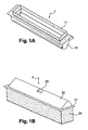
- the Figure 1A represents a perspective view of the cartridge of the system of the invention.
- This cartridge 1 comprises a receptacle 10 for receiving toner.
- This receptacle 10 is surmounted by a frame 11 fixed on the receptacle.
- a lid closes the cartridge.
- This cover is removably attached to the frame 11 of the cartridge 1. It is easily removable by the user. Indeed, this cover must be removed from the cartridge when a refill is put in place. That's why this lid is not represented on the Figure 1A .
- the Figure 1B represents a refill of the system of the invention.
- This recharge 2 of the Figure 1B is adapted to be inserted into the cartridge of the Figure 1A . It comprises a frame 20 and a rotating container 22 in the frame 20.
- the frame 20 of the refill 2 comprises a flange 21 forming a recess on the upper part of the frame. This flange 21 serves as a stop for the refill 2, when it is inserted into the cartridge 1.
- the container 22 is pivotally mounted about a longitudinal axis of rotation, fixed on the frame. An exemplary form of the container 22 will be described later.
- This container 22 may comprise a notch 23, made on the opposite side to the axis of rotation, to indicate to the user the location where the support must be to open the container.
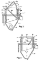
- the figure 2 is a sectional side view of the cartridge and refill system of the invention.
- This figure shows the cartridge 1 with its receptacle 10 at the bottom of which are one or more rollers 4 for spreading the toner output 5 of the receptacle 10. These rolls are identical to those of conventional printing devices.
- the receptacle 10 contains the toner. When the cartridge is new, this receptacle is initially filled with toner. When the cartridge is refilled, it is filled with the toner initially contained in the container. In other words, the toner contained in the container 22 of the refill is intended to be poured into the receptacle 10 of the cartridge 1.
- the receptacle 10 is surmounted by a frame 11 fixed to the receptacle by any known means, such as glue. It can also be overmoulded on the receptacle 10. Initially, when the cartridge is new, the frame 11 is closed by a cover placed and fixed on said frame 11. During the second use of the cartridge, that is to say when the cartridge is recharged, the lid is removed and it is the refill that bears on the frame 11.
- the figure 2 shows the preferred form for the container 22 of the refill 2.
- the container has a substantially triangular section.
- the container comprises three sides 22a, 22b and 22c.
- the side 22a forms the base of the triangle, opposite the top 22e.
- the sides 22b and 22c meet around the axis of rotation 3.
- the side 22c forms a circular arc 22d about the axis 3 to facilitate the rotation of the container in the cartridge.
- the container side 22b forms an angle of approximately 45 ° with the chassis surface; it is understood that this angle may vary, depending in particular on the shape of the container, while remaining less than 90 °.
- the base 22a is partly open, over the entire length of the refill. In other words, the base 22a does not completely close the container 22.
- the container 22 is closed by the frame 20 of the refill. So, as it will be seen in more detail later, the container 22 has a closed position, which is the one shown on the figure 2 , in which the toner is contained entirely in the container closed by the frame.
- An open position which will be described later, makes it possible to rotate the container around the axis 3 and thus to tilt said container so that the opening in the base 22a is facing the receptacle of the cartridge.
- the frame 20 of the refill 2 has vertical walls 20a and 20b which can be of different lengths.
- the walls 20a and 20b end at their upper end by a collar 21.
- This collar 21 may be uniform over the entire contour of the refill. It can also have different shapes depending on the considered faces of the refill.
- the flange 21 may form a right angle with the wall 20a of the frame, as shown by reference 21a. It can also form a half U with the wall 20b of the frame, as shown by reference 21 b. Whatever its shape, the flange 21 has the role of providing abutment against the frame of the cartridge. The refill can not be introduced too deeply into the cartridge by the user.
- the wall 20a of the frame may be covered with a sealing material 26, for example a foam, sealing the container when it is in the closed position.
- a sealing material 26 for example a foam
- This anti-dismounting device 12, 27, also called non-return, comprises at least one lug 12 located inside the receptacle 10 of the cartridge and at least one orifice 27 formed in the wall 20b of the frame 20 of the refill.
- the lug 12 is intended to fit into the orifice 27 so as to prevent disassembly of the refill once it has been inserted into the cartridge. Only one refill can be introduced into the cartridge. Once the refill toner has been fully used, it is mechanically impossible for the user to pop the refill out of the cartridge.
- the lug 12 is a rack, molded on the inner face of the receptacle and directed towards the bottom of the receptacle 10.
- the rack 12 is easily introduced into the orifice 27 when the refill is pushed towards the bottom of the receptacle.
- the rack 12 is in abutment against the portion of the wall 20b surrounding the orifice 27, which prevents the refill can be pulled up the cartridge.
- the container 22 has a shape whose section is substantially triangular.
- the base 22a of the container is convex which allows to increase the interior volume of the container. It is understood that other forms can be envisaged for the container, such as a straight base.
- top 22e of the container 22 is shown with a partially rounded half-U shape which is inserted into the collar 21 around the axis of rotation 3. It should be noted that the shape of the top 22d and the flange 21b may differ depending on the embodiments.
- FIG 3 schematically shows a sectional side view of the system of the invention, when the container of the refill is in the open position.
- the side 22b of the container 22 forms, with the surface of the flange 21, a flat angle.
- the 22c side of the container 22 is then parallel to the wall 20b of the frame.
- the base 22a is inside the chassis. The convex shape of the base 22a ensures a good flow of the toner to the receptacle 10, without any toner retention.
- the user To move from the closed position of the container 22, shown on the figure 2 , at the open position of the container, shown on the figure 3 , the user simply has to push on the side 22b of the container, preferably on the notch 23. This pressure has the effect of pivoting the container downwards, putting the open part of the base 22a facing the receptacle 10 of the cartridge. The toner then escapes from the container 22 according to the arrow represented on the figure 3 .
- the toner escapes over the entire length of the container. Thus, it is distributed homogeneously in the receptacle. There is no need, before positioning the refill in the cartridge, to shake the refill to distribute the toner. Indeed, the refill is usually full. Also, when it evacuates container, the toner is distributed homogeneously and evenly in the receptacle at the time of opening of the container.
- the container 22 In the open position, the container 22 is fully inserted into the cartridge and the outer shape of the cartridge is identical to the shape of a new cartridge.
- the cartridge can therefore be reused, by the user, exactly like a new cartridge.
- the refill cartridge system of the invention is clean since there is no contact with toner emanation when transferring it from the refill to the cartridge.
- the new cartridge may have a protective film sealed to the cartridge frame.
- this film is located under the cartridge cover.
- This protective film can be made of a plastic material, such as a very thin polycarbonate, or in aluminum.
- the protective film may also comprise reduced areas easy to pierce, so that, when it is put in place in the cartridge, the refill pierces the protective film at predetermined locations, for example in the center of the film. Once the film is pierced, the pieces of the film are distributed all around the refill so as not to hinder the evacuation of the toner.
- this locking device comprises a deformable locking finger 6.
- This finger of locking 6 can be made in the same material as the refill, that is to say in ABS or PS.
- the container 22 forms a recess 22 '.
- the side 22c of the container is locally perpendicular to the foam 26, as shown by the reference 22 '.
- the dotted lines show the general shape of the container 22, out of proximity of the locking finger.
- the locking finger 6 is fixed and deforms as the refill passes through the receptacle of the cartridge. It can have two positions: an outer position in which it is partly outside the receptacle and an inner position in which it is entirely housed in the receptacle.
- the locking finger 6 has been shown when in its outer position, that is to say partly out of the receptacle of the cartridge. In this position, the locking finger has a curved shape which has the effect that the finger retains the side 22c of the container.
- the container can not open. As long as the refill is not correctly installed in the cartridge, the locking finger holds the container in its closed position. There is therefore no possible evacuation of the toner.
- the locking finger is pressed into a housing 7 of the receptacle.
- the container can then open.
- the cartridge can be reloaded without being removed from its location in the printing device. Indeed, since most of the printing device opens at the top, by a cover to open or part of the device to be removed, reloading the cartridge from above allows the reloading can be done in place in the device, without necessarily removing the cartridge from its housing.
- a user who orders a cartridge receives both a new cartridge and a refill.
- he uses the cartridge alone to make his impressions.
- the cartridge When the cartridge is empty of any toner, it can fill it with the refill. He must then remove the cover of the cartridge, easy to disassemble. Since there is no more toner in the cartridge, the lid is clean, especially if the cartridge has a protective film. The lid can be thrown into the trash without any difficulty.
- the user introduces the refill into the cartridge and pushes the refill until the frame comes to rest on the frame of the cartridge. At this time, the refill is in its correct position and the user can press the prominent part of the container thus passing the container from its closed position to its open position.
- the toner is then evacuated homogeneously as the container is opened in the receptacle of the cartridge.
- the user then only has to use the cartridge as a new cartridge.
- the dimensions of the refill are designed so that the refill fits into the cartridge and that it retains the same size as a new cartridge, the thickness of the rim of the frame then replacing the thickness of the lid of the new cartridge.
- This cartridge refill system has the advantage of being simple and quick to implement.
Abstract
Description
L'invention concerne un système de cartouche de toner à recharge unique destiné à être utilisé dans un dispositif d'impression du type imprimante ou télécopieur. Ce système de cartouche comporte une cartouche de toner qui, lorsqu'elle est vide, peut être rechargée une seule fois par une recharge adaptée à cette cartouche. L'invention concerne aussi un procédé pour mettre en oeuvre ce système.The invention relates to a single-refill toner cartridge system for use in a printer or facsimile type printing device. This cartridge system includes a toner cartridge which, when empty, can be refilled once with a refill adapted to that cartridge. The invention also relates to a method for implementing this system.
D'une façon générale, l'invention trouve des applications dans le domaine de l'impression numérique. Elle trouve, en particulier, des applications dans le domaine de l'impression par des dispositifs informatiques tels que des imprimantes, des photocopieurs ou des télécopieurs.In general, the invention has applications in the field of digital printing. It finds, in particular, applications in the field of printing by computer devices such as printers, photocopiers or fax machines.
Actuellement, la plupart des dispositifs d'impression de type informatique utilisent une encre sèche, colorée ou noire, réduite en fines particules et contenant une résine sensible à la chaleur, qui se fixe par chauffage sur le support d'impression utilisé, par exemple, du papier. Cette encre est appelée généralement toner.Currently, most computer-like printing devices use a dry, colored or black ink, reduced in fine particles and containing a heat-sensitive resin, which is fixed by heating on the printing medium used, for example paper. This ink is generally called toner.
Pour une utilisation efficace, ce toner est placé dans une cartouche située à l'intérieur de l'appareil. Chaque cartouche de toner est prévue pour un nombre limité de pages imprimées, par exemple 3000 ou 5000 pages. Lorsque la cartouche est vide, deux possibilités s'offrent à l'utilisateur de l'appareil : soit il remplace la cartouche vide par une nouvelle cartouche pleine, soit il remplit à nouveau la cartouche avec du toner en bouteille.For effective use, this toner is placed in a cartridge inside the machine. Each toner cartridge is intended for a limited number of printed pages, for example 3000 or 5000 pages. When the cartridge is empty, there are two possibilities for the user of the device: either he replaces the empty cartridge with a new full cartridge, or he refills the cartridge with bottled toner.
Le changement d'une cartouche a l'inconvénient de présenter un coût relativement élevé. En effet, une cartouche entière a un coût nettement plus important que du toner en bouteille. Aussi, la plupart des utilisateurs choisissent de remplir la cartouche avec du toner vendu en bouteille. Dans ce cas, pour remplir la cartouche, l'utilisateur doit ouvrir la cartouche, ouvrir la bouteille de toner et verser directement le toner dans la cartouche. Or, le toner est une fine poudre qui s'envole facilement, en particulier lorsqu'elle est transvasée d'un récipient vers un autre récipient. De plus, cette fine poudre est colorée. Elle salit donc les éléments situés autour de la cartouche à remplir ainsi que les mains et les vêtements de l'utilisateur. En outre, le fait d'ouvrir le bouchon de la cartouche entraîne également des salissures sur les mains de l'utilisateur et de inhalations de vapeur de toner qui peuvent nuire à la santé de l'utilisateur. l'ouverture du bouchon peut, en plus, détériorer le bouchon. Cette technique est donc, non seulement salissante, mais en plus elle est relativement longue à mettre en oeuvre.The change of a cartridge has the disadvantage of having a relatively high cost. Indeed, an entire cartridge has a significantly higher cost than bottled toner. Also, most users choose to fill the cartridge with toner sold in bottles. In this case, to fill the cartridge, the user must open the cartridge, open the toner bottle and directly pour the toner into the cartridge. Toner is a fine powder that flakes easily, especially when is transferred from one container to another container. In addition, this fine powder is colored. It therefore dirty the elements around the cartridge to be filled and the hands and clothes of the user. In addition, opening the cap of the cartridge also causes dirt on the user's hands and inhalations of toner vapor that can affect the health of the user. the opening of the plug can, in addition, deteriorate the plug. This technique is therefore not only messy, but in addition it is relatively long to implement.
Par ailleurs, cette technique ne permet pas de contrôler la durée de vie des composants de la cartouche et, en particulier, des rouleaux de la cartouche qui peuvent s'encrasser et détériorer la qualité de l'impression, voire rendre le dispositif d'impression inutilisable.Moreover, this technique does not make it possible to control the life of the components of the cartridge and, in particular, the rollers of the cartridge which can become dirty and deteriorate the quality of the printing, or even make the printing device unusable.
Pour résoudre ces problèmes, il existe des recharges de toner destinées à être placées dans la cartouche de toner vide. Le document
Le document
Par ailleurs, lorsque l'utilisateur a ouvert la recharge, il se retrouve avec une languette, couverte de toner, dont il ne sait que faire. Généralement, l'utilisateur met alors cette languette dans une poubelle. Or, en France et dans de nombreux pays, la législation impose, aux fabricants de cartouches de toner et de recharges de toner, de récupérer les emballages sales, c'est-à-dire comportant du toner, afin de les recycler. En conséquence, les fabricants de cartouches et de recharges de toner demandent aux utilisateurs de renvoyer la cartouche et/ou la recharge une fois que celle-ci a été utilisée. Cependant, si la plupart des utilisateurs renvoient généralement les éléments principaux, ils ne renvoient pas la languette couverte de toner pour la simple raison qu'ils seraient obligés de stocker la languette sale tant que la cartouche ou la recharge n'est pas vide.Moreover, when the user has opened the refill, he is left with a tab, covered with toner, which he does not know what to do. Generally, the user then puts this tab in a bin. However, in France and in many countries, the legislation requires the manufacturers of toner cartridges and toner refills, recover the dirty packaging, that is to say, with toner, for recycling. As a result, the manufacturers of toner cartridges and refills ask users to return the cartridge and / or the refill once it has been used. However, while most users typically return the main items, they do not return the toner-covered tab for the simple reason that they would be forced to store the dirty tab until the cartridge or refill is empty.
L'invention a justement pour but de remédier aux inconvénients des techniques exposées précédemment. A cette fin, l'invention propose système de cartouche à recharge de toner unique comportant une cartouche pleine de toner et une recharge à insérer dans la cartouche, de manière simple et propre, lorsque la cartouche est vide. Ce système de cartouche à recharge permet, en effet, de recharger une cartouche de toner sans avoir à tirer une languette ou tout autre élément pouvant être empreint de toner. Pour cela, la recharge de toner comporte un container à l'intérieur duquel se trouve, initialement, le toner. Ce container est rotatif dans la cartouche de sorte que, dans une position fermée, le toner est contenu à l'intérieur du container et, dans une position ouverte, le toner s'évacue vers le réceptacle de la cartouche. Le passage de la position fermée à la position ouverte du container est réalisé par simple appui, par l'utilisateur, sur le container.The purpose of the invention is precisely to overcome the disadvantages of the techniques described above. To this end, the invention proposes a single toner refill cartridge system comprising a full cartridge of toner and a refill to be inserted into the cartridge, in a simple and clean way, when the cartridge is empty. This refill cartridge system makes it possible to refill a toner cartridge without having to pull a tab or any other element that can be stamped with toner. For this, the toner refill comprises a container inside which is initially the toner. This container is rotatable in the cartridge so that, in a closed position, the toner is contained within the container and, in an open position, the toner is evacuated to the cartridge receptacle. The passage from the closed position to the open position of the container is achieved simply by pressing the user on the container.
Ce système de cartouche à recharge unique permet de recharger la cartouche de façon propre, sans que l'utilisateur ne soit à un quelconque moment en contact direct avec le toner. Il permet également d'assurer un recyclage complet de l'ensemble cartouche et recharge puisque, lorsque la recharge a été introduite dans la cartouche, elle ne peut plus être retirée de la cartouche. Aussi, lorsque la recharge est vide, l'utilisateur renvoie l'ensemble cartouche et recharge au fabricant qui a alors, à sa disposition, tous les éléments «sales » nécessitant un recyclage.This single-refill cartridge system allows the cartridge to be recharged cleanly without the user being in direct contact with the toner at any time. It also ensures complete recycling of the cartridge and refill assembly since, when the refill has been introduced into the cartridge, it can no longer be removed from the cartridge. Also, when the refill is empty, the user returns the cartridge and refill assembly to the manufacturer who then has at his disposal all the "dirty" elements requiring recycling.
Ce système présente aussi l'avantage de permettre au fabricant de contrôler la durée de vie des composants et, notamment, leur encrassement en limitant le nombre possible de pages imprimées. En d'autres termes, si le fabricant sait que les composants ont une durée de vie de 10000 pages, il adapte la quantité de toner dans la cartouche et la recharge de façon à ce que le nombre de pages ne dépasse pas 10000.This system also has the advantage of allowing the manufacturer to control the life of the components and, in particular, their clogging by limiting the possible number of printed pages. In other words, if the manufacturer knows that the components have a life of 10000 pages, he adapts the amount of toner in the cartridge and the refill so that the number of pages does not exceed 10000.
Ce système a, en outre, l'avantage d'être moins coûteux pour l'utilisateur que deux cartouches, pour un nombre de pages identique avec une bonne garantie d'impression.This system also has the advantage of being less expensive for the user than two cartridges, for an identical number of pages with a good print guarantee.
De façon plus précise, l'invention concerne un système de cartouche à recharge de toner selon la revendication 1. :More specifically, the invention relates to a toner refill cartridge system according to claim 1.
L'invention concerne également un procédé de mise en oeuvre du système de cartouche à recharge selon la revendication 13.The invention also relates to a method of implementing the refill cartridge system according to claim 13.
-
Les
figures 1A et 1B montrent une vue en perspective, respectivement, d'une cartouche et d'une recharge du système de l'invention.TheFigures 1A and 1B show a perspective view, respectively, of a cartridge and a refill of the system of the invention. -
La
figure 2 représente une vue en coupe d'une recharge insérée dans une cartouche, lorsque le container de la recharge est en position fermée.Thefigure 2 represents a sectional view of a refill inserted into a cartridge, when the container of the refill is in the closed position. -
La
figure 3 représente une vue en coupe de la recharge insérée dans une cartouche, lorsque le container de la recharge est en position ouverte.Thefigure 3 represents a sectional view of the refill inserted in a cartridge, when the container of the refill is in the open position. -
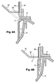
La
figure 4A représente un dispositif d'anti-ouverture de la recharge lorsque la recharge n'est pas entièrement introduite dans la cartouche.TheFigure 4A represents an anti-opening device of the refill when the refill is not fully introduced into the cartridge. -
La
figure 4B représente le dispositif d'anti-ouverture de la recharge lorsque la recharge est entièrement introduite dans la cartouche.TheFigure 4B represents the anti-opening device of the refill when the refill is fully introduced into the cartridge.
Le système de l'invention comporte une cartouche de toner qui, une fois vide, peut être rechargée au moyen d'une recharge de toner adaptée. La
A l'origine, c'est-à-dire lorsque la cartouche est neuve, un couvercle ferme la cartouche. Ce couvercle est fixé de manière amovible sur le cadre 11 de la cartouche 1. Il est facilement démontable par l'utilisateur. En effet, ce couvercle doit être retiré de la cartouche lorsqu'une recharge est mise en place. C'est pourquoi, ce couvercle n'est pas représenté sur la
La
Le châssis 20 de la recharge 2 comporte une collerette 21 formant un décrochement sur la partie supérieure du châssis. Cette collerette 21 sert de butée à la recharge 2, lorsque celle-ci est insérée dans la cartouche 1.The
Le container 22 est monté pivotant autour d'un axe de rotation longitudinal, fixé sur le châssis. Un exemple de forme du container 22 sera décrit ultérieurement. Ce container 22 peut comporter une encoche 23, réalisée sur le coté opposé à l'axe de rotation, pour indiquer à l'utilisateur l'emplacement où doit se faire l'appui pour ouvrir le container.The
La
Le réceptacle 10 contient le toner. Lorsque la cartouche est neuve, ce réceptacle est rempli initialement avec du toner. Lorsque la cartouche est rechargée, elle est remplie avec le toner initialement contenu dans le container. Autrement dit, le toner contenu dans le container 22 de la recharge est destiné à être déversé dans le réceptacle 10 de la cartouche 1.The
Le réceptacle 10 est surmonté d'un cadre 11 fixé sur le réceptacle par tout moyen connu, comme la colle. Il peut aussi être surmoulé sur le réceptacle 10. Initialement, lorsque la cartouche est neuve, le cadre 11 est fermé par un couvercle posé et fixé sur ledit cadre 11. Lors de la seconde utilisation de la cartouche, c'est-à-dire lorsque la cartouche est rechargée, le couvercle est retiré et c'est la recharge qui est en appui sur le cadre 11.The
La
La base 22a est en partie ouverte, sur toute la longueur de la recharge. Autrement dit, la base 22a ne ferme pas entièrement le container 22. Le container 22 est fermé par le châssis 20 de la recharge. Ainsi, comme on le verra plus en détail par la suite, le container 22 comporte une position fermée, qui est celle montrée sur la
Le châssis 20 de la recharge 2 comporte des parois verticales 20a et 20b pouvant être de longueurs différentes. Les parois 20a et 20b se terminent, à leur extrémité supérieure, par une collerette 21. Cette collerette 21 peut être uniforme sur tout le contour de la recharge. Elle peut aussi avoir des formes différentes selon les faces considérées de la recharge. Par exemple, la collerette 21 peut former un angle droit avec la paroi 20a du châssis, comme montré par la référence 21 a. Elle peut aussi former un demi U avec la paroi 20b du châssis, comme montré par la référence 21 b. Quelle que soit sa forme, la collerette 21 a pour rôle d'assurer un appui en butée sur le cadre de la cartouche. La recharge ne peut donc être introduite trop profondément dans la cartouche par l'utilisateur.The
Comme on le voit sur cette
Sur la
Dans le mode de réalisation de la
Dans le mode de réalisation qui vient d'être décrit, le container 22 a une forme dont la section est sensiblement triangulaire. Toutefois, comme on le voit sur la
De même, sur la
Sur la
Pour passer de la position fermée du container 22, montrée sur la
En passant de la position fermée à la position ouverte, le toner s'échappe sur toute la longueur du container. Ainsi, il se répartit de façon homogène dans le réceptacle. Il n'y a donc pas besoin, avant de positionner la recharge dans la cartouche, de secouer la recharge pour répartir le toner. En effet, la recharge est généralement pleine. Aussi, lorsqu'il s'évacue du container, le toner se répartit de façon homogène et régulière dans le réceptacle au moment de l'ouverture du container.Moving from the closed position to the open position, the toner escapes over the entire length of the container. Thus, it is distributed homogeneously in the receptacle. There is no need, before positioning the refill in the cartridge, to shake the refill to distribute the toner. Indeed, the refill is usually full. Also, when it evacuates container, the toner is distributed homogeneously and evenly in the receptacle at the time of opening of the container.
En position ouverte, le container 22 est totalement inséré dans la cartouche et la forme extérieure de la cartouche est identique à la forme d'une cartouche neuve. La cartouche peut donc être réutilisée, par l'utilisateur, exactement comme une cartouche neuve.In the open position, the
L'utilisateur a ainsi rechargé sa cartouche sans se salir, car il n'est jamais en contact direct avec le toner. Autrement dit, le système de cartouche à recharge de l'invention est propre puisqu'il n'y a aucun contact avec émanation de toner lors du transfert de celui-ci de la recharge vers la cartouche.The user has reloaded his cartridge without getting dirty because he is never in direct contact with the toner. In other words, the refill cartridge system of the invention is clean since there is no contact with toner emanation when transferring it from the refill to the cartridge.
Pour assurer encore une meilleure protection contre les émanations de toner et pour ne pas salir le couvercle, la cartouche neuve peut comporter un film de protection scellé sur le cadre de la cartouche. Lorsque la cartouche est neuve, ce film est situé sous le couvercle de la cartouche. Ainsi, lorsque l'utilisateur retire le couvercle de la cartouche, en particulier avant que la cartouche ne soit complètement vide, il ne peut être en contact avec aucun résidu éventuel de toner. Ce film de protection peut être réalisé dans une matière plastique , comme un polycarbonate très fin, ou bien dans de l'aluminium. Au début de l'insertion de la recharge dans la cartouche, le film est percé par le châssis de la recharge. Pour un percement plus aisé, les bords du châssis peuvent être biseautés, facilitant le découpage du film. Le film de protection peut aussi comporter des zones amoindries faciles à percer, de façon à ce que, lors de sa mise en place dans la cartouche, la recharge perce ce film de protection à des emplacements prédéterminés, par exemple au centre du film. Une fois le film percé, les morceaux du film se répartissent tout autour de la recharge de façon à ne pas gêner l'évacuation du toner.To ensure even better protection against toner fumes and soiling the lid, the new cartridge may have a protective film sealed to the cartridge frame. When the cartridge is new, this film is located under the cartridge cover. Thus, when the user removes the lid from the cartridge, in particular before the cartridge is completely empty, it can not come into contact with any residual toner. This protective film can be made of a plastic material, such as a very thin polycarbonate, or in aluminum. At the beginning of the insertion of the refill in the cartridge, the film is pierced by the frame of the refill. For easier drilling, the edges of the frame can be beveled, facilitating the cutting of the film. The protective film may also comprise reduced areas easy to pierce, so that, when it is put in place in the cartridge, the refill pierces the protective film at predetermined locations, for example in the center of the film. Once the film is pierced, the pieces of the film are distributed all around the refill so as not to hinder the evacuation of the toner.
Sur les
A proximité de ce doigt de verrouillage, le container 22 forme un décrochement 22'. Autrement dit, le coté 22c du container est localement perpendiculaire à la mousse 26, comme montré par la référence 22'. Les traits en pointillés montrent la forme générale du container 22, hors proximité du doigt de verrouillage.In the vicinity of this locking finger, the
Le doigt de verrouillage 6 est fixe et se déforme au passage de la recharge dans le réceptacle de la cartouche. Il peut avoir deux positions : une position extérieure dans laquelle il est en partie en extérieur du réceptacle et une position intérieure dans laquelle il se trouve entièrement logé dans le réceptacle.The locking
Sur la
Lorsque la recharge est correctement insérée dans la cartouche, c'est-à-dire que le coté 22c du container atteint le réceptacle, comme montré sur la
Avec le système de cartouche à recharge qui vient d'être décrit, la cartouche peut être rechargée sans être sortie de son emplacement dans le dispositif d'impression. En effet, comme la plupart des dispositif d'impression s'ouvrent par le haut, par un capot à ouvrir ou une partie du dispositif à retirer, le fait de recharger la cartouche par le haut permet que le rechargement puisse se faire en place dans le dispositif, sans nécessairement sortir la cartouche de son logement.With the refill cartridge system just described, the cartridge can be reloaded without being removed from its location in the printing device. Indeed, since most of the printing device opens at the top, by a cover to open or part of the device to be removed, reloading the cartridge from above allows the reloading can be done in place in the device, without necessarily removing the cartridge from its housing.
Avec le système qui vient d'être décrit, un utilisateur qui commande une cartouche reçoit à la fois une cartouche neuve et une recharge. Dans un premier temps, il utilise la cartouche seule pour réaliser ses impressions. Lorsque la cartouche est vide de tout toner, il peut la remplir au moyen de la recharge. Il doit alors retirer le couvercle de la cartouche, simple à démonter. Comme il n'y a plus de toner dans la cartouche, le couvercle est propre, en particulier si la cartouche comporte un film de protection. Le couvercle peut donc être jeté dans la poubelle sans aucune difficulté. Ensuite, l'utilisateur introduit la recharge dans la cartouche et enfonce la recharge jusqu'à ce que le châssis vienne en appui sur le cadre de la cartouche. A ce moment, la recharge est dans sa position correcte et l'utilisateur peut appuyer sur la partie proéminente du container faisant ainsi passer le container de sa position fermée à sa position ouverte. Le toner s'évacue alors, de façon homogène, au fur et à mesure de l'ouverture du container dans le réceptacle de la cartouche. L'utilisateur n'a alors plus qu'à utiliser la cartouche comme une cartouche neuve. En effet, les dimensions de la recharge sont prévues pour que la recharge s'adapte dans la cartouche et que celle-ci conserve la même dimension qu'une cartouche neuve, l'épaisseur du rebord du châssis venant alors remplacer l'épaisseur du couvercle de la cartouche neuve.With the system just described, a user who orders a cartridge receives both a new cartridge and a refill. At first, he uses the cartridge alone to make his impressions. When the cartridge is empty of any toner, it can fill it with the refill. He must then remove the cover of the cartridge, easy to disassemble. Since there is no more toner in the cartridge, the lid is clean, especially if the cartridge has a protective film. The lid can be thrown into the trash without any difficulty. Then, the user introduces the refill into the cartridge and pushes the refill until the frame comes to rest on the frame of the cartridge. At this time, the refill is in its correct position and the user can press the prominent part of the container thus passing the container from its closed position to its open position. The toner is then evacuated homogeneously as the container is opened in the receptacle of the cartridge. The user then only has to use the cartridge as a new cartridge. Indeed, the dimensions of the refill are designed so that the refill fits into the cartridge and that it retains the same size as a new cartridge, the thickness of the rim of the frame then replacing the thickness of the lid of the new cartridge.
Une fois que cette cartouche avec sa recharge a été utilisée, l'utilisateur renvoie le tout, c'est-à-dire la cartouche avec la recharge à l'intérieur, au fabricant qui peut alors la recycler. Ce système de cartouche à recharge a l'avantage d'être simple et rapide à mettre en oeuvre.Once this cartridge with its refill has been used, the user returns the whole thing, that is to say the cartridge with the refill inside, the manufacturer who can then recycle it. This cartridge refill system has the advantage of being simple and quick to implement.
Claims (14)
- Toner refill cartridge system, comprising:- a cartridge (1) including a receiver (10) topped by a frame (11),- a toner refill (2) able to be inserted into the receiver in the cartridge and comprising a container (22) containing the toner, and- a chassis (20) able to be fitted into the receiver in the cartridge, characterized in that- the container includes a partly open base (22a) over the length of the refill,- the container is mounted so as to pivot around an axis of rotation (3) fixed to the chassis so that the container has a closed position in which the toner is contained in the container by closing the opening in the base of said container with the chassis and an open position in which the opening in the base is located in front of the receiver in the cartridge in order to empty the toner from said container into the receiver in the cartridge.
- System according to claim 1, characterized in that the container has a substantially triangular section with an apex (22e) pivoting around the axis of rotation and with a partly open base (22a).
- System according to any one of the claims 1 to 2, characterized in that, in the closed position, the container has a side (22b) forming a not flat angle, inferior to 90°, with the upper surface of the chassis.
- System according to any one of the claims 1 to 3, characterized in that, in the open position, the container has a side (22b) forming a flat angle with the upper surface of the chassis.
- System according to any one of the claims 2 to 4, characterized in that, in the closed position of the container, the open part of the base (22a) is closed by a wall (20a) of the chassis (20) of the container.
- System according to claim 5, characterized in that at least the wall (20a) of the chassis closing the container is covered with a layer of a sealing material.
- System according to any one of the claims 1 to 6, characterized in that the chassis of the refill comprises a flange (21) supported by the frame (11) of the cartridge.
- System according any one of the claims 1 to 7, characterized in that the receiver (10) in the cartridge comprises an anti-dismounting device for the refill.
- System according to claim 8, characterized in that the anti-dismounting device comprises at least one retention pin (12) and the chassis of the refill includes at least one orifice (27) in which the retention pin is inserted.
- System according to any one of the claims 1 to 9, characterized in that the cartridge comprises a locking finger (6) holding the container in the closed position as long as the refill is not correctly inserted into the cartridge.
- System according to claim 10, characterized in that the locking finger is made of a deformable material.
- System according to any one of the claims 1 to 11, characterized in that the cartridge comprises a protective film fixed to the surface of the frame.
- Method for using the toner refill cartridge system according to any one of the claims 1 to 12, characterized in that it comprises the following operations:- removing a cover from the cartridge,- inserting the refill (2) into the cartridge (1) until the flange (21) of the refill is supported by the frame (11) of the refill,- pressing a side (22b) of the container in the refill in order to switch said container from the closed position to the open position.
- Method according to claim 13, characterized in that the refill is inserted into the cartridge when there is no more toner in said cartridge.
Applications Claiming Priority (2)
| Application Number | Priority Date | Filing Date | Title |
|---|---|---|---|
| FR0351183A FR2864263B1 (en) | 2003-12-23 | 2003-12-23 | SINGLE RECHARGE TONER CARTRIDGE SYSTEM AND METHOD FOR IMPLEMENTING SAME |
| FR0351183 | 2003-12-23 |
Publications (3)
| Publication Number | Publication Date |
|---|---|
| EP1548520A2 EP1548520A2 (en) | 2005-06-29 |
| EP1548520A3 EP1548520A3 (en) | 2010-09-15 |
| EP1548520B1 true EP1548520B1 (en) | 2012-02-22 |
Family
ID=34531406
Family Applications (1)
| Application Number | Title | Priority Date | Filing Date |
|---|---|---|---|
| EP04300947A Not-in-force EP1548520B1 (en) | 2003-12-23 | 2004-12-23 | Tonercartridge with unique reloading and method therefor |
Country Status (4)
| Country | Link |
|---|---|
| EP (1) | EP1548520B1 (en) |
| AT (1) | ATE546761T1 (en) |
| ES (1) | ES2381044T3 (en) |
| FR (1) | FR2864263B1 (en) |
Family Cites Families (8)
| Publication number | Priority date | Publication date | Assignee | Title |
|---|---|---|---|---|
| US4307763A (en) * | 1979-11-29 | 1981-12-29 | International Business Machines Corporation | Toner container |
| DK418883A (en) * | 1982-09-21 | 1984-03-22 | Xerox Corp | PARTICLE MATERIAL TRANSMISSION DEVICE |
| US4523834A (en) * | 1984-01-09 | 1985-06-18 | Pitney Bowes Inc. | Dry toner replenishing apparatus |
| DE3641077A1 (en) * | 1986-12-02 | 1988-06-09 | Eisbein Develop | Toner station for a copying device or the like |
| EP0483440B1 (en) * | 1990-10-30 | 1994-06-01 | BULL HN INFORMATION SYSTEMS ITALIA S.p.A. | Electrophotographic toner cartridge |
| JPH05289515A (en) * | 1992-04-15 | 1993-11-05 | Konica Corp | Image forming device |
| US5832343A (en) * | 1995-04-03 | 1998-11-03 | Canon Kabushiki Kaisha | Toner supply method, toner accommodation container, process cartridge and electrophotographic image forming apparatus |
| US5907747A (en) * | 1998-02-02 | 1999-05-25 | Ward Sealing, Inc. | Prefilled, presealed toner cartridge insert |
-
2003
- 2003-12-23 FR FR0351183A patent/FR2864263B1/en not_active Expired - Fee Related
-
2004
- 2004-12-23 AT AT04300947T patent/ATE546761T1/en active
- 2004-12-23 ES ES04300947T patent/ES2381044T3/en active Active
- 2004-12-23 EP EP04300947A patent/EP1548520B1/en not_active Not-in-force
Also Published As
| Publication number | Publication date |
|---|---|
| EP1548520A3 (en) | 2010-09-15 |
| FR2864263B1 (en) | 2006-04-07 |
| ES2381044T3 (en) | 2012-05-22 |
| EP1548520A2 (en) | 2005-06-29 |
| FR2864263A1 (en) | 2005-06-24 |
| ATE546761T1 (en) | 2012-03-15 |
Similar Documents
| Publication | Publication Date | Title |
|---|---|---|
| EP0521188B1 (en) | Device for extracting cartridges | |
| EP0293290B1 (en) | Closure device for containers | |
| FR2753410A1 (en) | INK CARTRIDGE AND ITS LOADING MECHANISM | |
| FR2688197A1 (en) | DISTRIBUTOR CLOSURE WITH TIP COLLAR. | |
| EP0910273A1 (en) | Paper dispenser containing a removable case | |
| FR2930460A1 (en) | FRAGRANCE DISTRIBUTOR. | |
| WO1997009082A1 (en) | Device for the pre-dosing of a powdery product for a product dispenser | |
| FR2620422A1 (en) | CARTRIDGE TANK | |
| FR3010286A1 (en) | CONTAINER WITH MAKEUP PRODUCT | |
| FR2496915A1 (en) | DEVICE FOR LOADING "TONER" IN THE TONER RESERVOIR OF A MACHINE | |
| EP2021263A1 (en) | Stopper member, fluid product dispenser comprising such a member and method of producing such a dispenser | |
| EP1216928A1 (en) | Device for storing and applying a liquid product | |
| EP1548520B1 (en) | Tonercartridge with unique reloading and method therefor | |
| FR2864262A1 (en) | Cartridge system for e.g. printer, has cartridge with container closed by cover and cylindrical refill inserted into container of cartridge through circular opening of cartridge | |
| FR2827577A1 (en) | Liquid dispenser comprises reservoir enclosed between base plate and upper plate with flexible section fitting over reservoir, spacer plate between these forming outlet channel | |
| FR2901373A3 (en) | TONER CARTRIDGE | |
| FR2796368A1 (en) | Dispenser for free samples of cosmetics comprises reservoir with deformable walls and dispensing outlet which has removable cover, both of which are enclosed in envelope whose top section can be removed to allow access to cover | |
| FR2833517A1 (en) | INK CARTRIDGE | |
| FR3037260A1 (en) | RECHARGEABLE DEVICE FOR FRAGRANCE AND COSMETIC PRODUCTS | |
| EP1546005A1 (en) | Dispensing device for fluid product | |
| EP4337561A1 (en) | Fluid product dispenser | |
| FR3041219A1 (en) | ||
| BE1004249A6 (en) | Container with lid and tear-off safety strip | |
| EP0889700B1 (en) | Apparatus for dispensing optionally folded wiping materials | |
| EP0675050A1 (en) | Sealing device for flexible walled container |
Legal Events
| Date | Code | Title | Description |
|---|---|---|---|
| PUAI | Public reference made under article 153(3) epc to a published international application that has entered the european phase |
Free format text: ORIGINAL CODE: 0009012 |
|
| AK | Designated contracting states |
Kind code of ref document: A2 Designated state(s): AT BE BG CH CY CZ DE DK EE ES FI FR GB GR HU IE IS IT LI LT LU MC NL PL PT RO SE SI SK TR |
|
| AX | Request for extension of the european patent |
Extension state: AL BA HR LV MK YU |
|
| RAP1 | Party data changed (applicant data changed or rights of an application transferred) |
Owner name: SAGEM COMMUNICATION |
|
| RAP1 | Party data changed (applicant data changed or rights of an application transferred) |
Owner name: SAGEM COMMUNICATIONS |
|
| RAP1 | Party data changed (applicant data changed or rights of an application transferred) |
Owner name: SAGEM COMMUNICATIONS SAS |
|
| RAP1 | Party data changed (applicant data changed or rights of an application transferred) |
Owner name: SAGEM COMMUNICATIONS |
|
| RAP1 | Party data changed (applicant data changed or rights of an application transferred) |
Owner name: SAGEM COMMUNICATIONS SAS |
|
| PUAL | Search report despatched |
Free format text: ORIGINAL CODE: 0009013 |
|
| AK | Designated contracting states |
Kind code of ref document: A3 Designated state(s): AT BE BG CH CY CZ DE DK EE ES FI FR GB GR HU IE IS IT LI LT LU MC NL PL PT RO SE SI SK TR |
|
| AX | Request for extension of the european patent |
Extension state: AL BA HR LV MK YU |
|
| RAP1 | Party data changed (applicant data changed or rights of an application transferred) |
Owner name: SAGEMCOM DOCUMENTS SAS |
|
| 17P | Request for examination filed |
Effective date: 20110207 |
|
| AKX | Designation fees paid |
Designated state(s): AT BE BG CH CY CZ DE DK EE ES FI FR GB GR HU IE IS IT LI LT LU MC NL PL PT RO SE SI SK TR |
|
| GRAP | Despatch of communication of intention to grant a patent |
Free format text: ORIGINAL CODE: EPIDOSNIGR1 |
|
| GRAS | Grant fee paid |
Free format text: ORIGINAL CODE: EPIDOSNIGR3 |
|
| GRAA | (expected) grant |
Free format text: ORIGINAL CODE: 0009210 |
|
| AK | Designated contracting states |
Kind code of ref document: B1 Designated state(s): AT BE BG CH CY CZ DE DK EE ES FI FR GB GR HU IE IS IT LI LT LU MC NL PL PT RO SE SI SK TR |
|
| REG | Reference to a national code |
Ref country code: GB Ref legal event code: FG4D Free format text: NOT ENGLISH |
|
| REG | Reference to a national code |
Ref country code: CH Ref legal event code: EP |
|
| REG | Reference to a national code |
Ref country code: AT Ref legal event code: REF Ref document number: 546761 Country of ref document: AT Kind code of ref document: T Effective date: 20120315 |
|
| REG | Reference to a national code |
Ref country code: IE Ref legal event code: FG4D Free format text: LANGUAGE OF EP DOCUMENT: FRENCH |
|
| REG | Reference to a national code |
Ref country code: DE Ref legal event code: R096 Ref document number: 602004036576 Country of ref document: DE Effective date: 20120419 |
|
| REG | Reference to a national code |
Ref country code: ES Ref legal event code: FG2A Ref document number: 2381044 Country of ref document: ES Kind code of ref document: T3 Effective date: 20120522 |
|
| REG | Reference to a national code |
Ref country code: NL Ref legal event code: VDEP Effective date: 20120222 |
|
| LTIE | Lt: invalidation of european patent or patent extension |
Effective date: 20120222 |
|
| PG25 | Lapsed in a contracting state [announced via postgrant information from national office to epo] |
Ref country code: LT Free format text: LAPSE BECAUSE OF FAILURE TO SUBMIT A TRANSLATION OF THE DESCRIPTION OR TO PAY THE FEE WITHIN THE PRESCRIBED TIME-LIMIT Effective date: 20120222 Ref country code: IS Free format text: LAPSE BECAUSE OF FAILURE TO SUBMIT A TRANSLATION OF THE DESCRIPTION OR TO PAY THE FEE WITHIN THE PRESCRIBED TIME-LIMIT Effective date: 20120622 Ref country code: NL Free format text: LAPSE BECAUSE OF FAILURE TO SUBMIT A TRANSLATION OF THE DESCRIPTION OR TO PAY THE FEE WITHIN THE PRESCRIBED TIME-LIMIT Effective date: 20120222 |
|
| PG25 | Lapsed in a contracting state [announced via postgrant information from national office to epo] |
Ref country code: FI Free format text: LAPSE BECAUSE OF FAILURE TO SUBMIT A TRANSLATION OF THE DESCRIPTION OR TO PAY THE FEE WITHIN THE PRESCRIBED TIME-LIMIT Effective date: 20120222 Ref country code: GR Free format text: LAPSE BECAUSE OF FAILURE TO SUBMIT A TRANSLATION OF THE DESCRIPTION OR TO PAY THE FEE WITHIN THE PRESCRIBED TIME-LIMIT Effective date: 20120523 Ref country code: PT Free format text: LAPSE BECAUSE OF FAILURE TO SUBMIT A TRANSLATION OF THE DESCRIPTION OR TO PAY THE FEE WITHIN THE PRESCRIBED TIME-LIMIT Effective date: 20120622 |
|
| REG | Reference to a national code |
Ref country code: IE Ref legal event code: FD4D |
|
| REG | Reference to a national code |
Ref country code: AT Ref legal event code: MK05 Ref document number: 546761 Country of ref document: AT Kind code of ref document: T Effective date: 20120222 |
|
| PG25 | Lapsed in a contracting state [announced via postgrant information from national office to epo] |
Ref country code: CY Free format text: LAPSE BECAUSE OF FAILURE TO SUBMIT A TRANSLATION OF THE DESCRIPTION OR TO PAY THE FEE WITHIN THE PRESCRIBED TIME-LIMIT Effective date: 20120222 |
|
| PG25 | Lapsed in a contracting state [announced via postgrant information from national office to epo] |
Ref country code: SI Free format text: LAPSE BECAUSE OF FAILURE TO SUBMIT A TRANSLATION OF THE DESCRIPTION OR TO PAY THE FEE WITHIN THE PRESCRIBED TIME-LIMIT Effective date: 20120222 Ref country code: RO Free format text: LAPSE BECAUSE OF FAILURE TO SUBMIT A TRANSLATION OF THE DESCRIPTION OR TO PAY THE FEE WITHIN THE PRESCRIBED TIME-LIMIT Effective date: 20120222 Ref country code: CZ Free format text: LAPSE BECAUSE OF FAILURE TO SUBMIT A TRANSLATION OF THE DESCRIPTION OR TO PAY THE FEE WITHIN THE PRESCRIBED TIME-LIMIT Effective date: 20120222 Ref country code: IE Free format text: LAPSE BECAUSE OF FAILURE TO SUBMIT A TRANSLATION OF THE DESCRIPTION OR TO PAY THE FEE WITHIN THE PRESCRIBED TIME-LIMIT Effective date: 20120222 Ref country code: EE Free format text: LAPSE BECAUSE OF FAILURE TO SUBMIT A TRANSLATION OF THE DESCRIPTION OR TO PAY THE FEE WITHIN THE PRESCRIBED TIME-LIMIT Effective date: 20120222 Ref country code: SE Free format text: LAPSE BECAUSE OF FAILURE TO SUBMIT A TRANSLATION OF THE DESCRIPTION OR TO PAY THE FEE WITHIN THE PRESCRIBED TIME-LIMIT Effective date: 20120222 Ref country code: PL Free format text: LAPSE BECAUSE OF FAILURE TO SUBMIT A TRANSLATION OF THE DESCRIPTION OR TO PAY THE FEE WITHIN THE PRESCRIBED TIME-LIMIT Effective date: 20120222 Ref country code: DK Free format text: LAPSE BECAUSE OF FAILURE TO SUBMIT A TRANSLATION OF THE DESCRIPTION OR TO PAY THE FEE WITHIN THE PRESCRIBED TIME-LIMIT Effective date: 20120222 |
|
| PG25 | Lapsed in a contracting state [announced via postgrant information from national office to epo] |
Ref country code: SK Free format text: LAPSE BECAUSE OF FAILURE TO SUBMIT A TRANSLATION OF THE DESCRIPTION OR TO PAY THE FEE WITHIN THE PRESCRIBED TIME-LIMIT Effective date: 20120222 |
|
| PLBE | No opposition filed within time limit |
Free format text: ORIGINAL CODE: 0009261 |
|
| STAA | Information on the status of an ep patent application or granted ep patent |
Free format text: STATUS: NO OPPOSITION FILED WITHIN TIME LIMIT |
|
| 26N | No opposition filed |
Effective date: 20121123 |
|
| PG25 | Lapsed in a contracting state [announced via postgrant information from national office to epo] |
Ref country code: AT Free format text: LAPSE BECAUSE OF FAILURE TO SUBMIT A TRANSLATION OF THE DESCRIPTION OR TO PAY THE FEE WITHIN THE PRESCRIBED TIME-LIMIT Effective date: 20120222 |
|
| REG | Reference to a national code |
Ref country code: DE Ref legal event code: R097 Ref document number: 602004036576 Country of ref document: DE Effective date: 20121123 |
|
| BERE | Be: lapsed |
Owner name: SAGEMCOM DOCUMENTS SAS Effective date: 20121231 |
|
| PG25 | Lapsed in a contracting state [announced via postgrant information from national office to epo] |
Ref country code: MC Free format text: LAPSE BECAUSE OF NON-PAYMENT OF DUE FEES Effective date: 20121231 Ref country code: BG Free format text: LAPSE BECAUSE OF FAILURE TO SUBMIT A TRANSLATION OF THE DESCRIPTION OR TO PAY THE FEE WITHIN THE PRESCRIBED TIME-LIMIT Effective date: 20120522 |
|
| REG | Reference to a national code |
Ref country code: CH Ref legal event code: PL |
|
| REG | Reference to a national code |
Ref country code: DE Ref legal event code: R082 Ref document number: 602004036576 Country of ref document: DE Representative=s name: BEETZ & PARTNER PATENT- UND RECHTSANWAELTE, DE |
|
| PG25 | Lapsed in a contracting state [announced via postgrant information from national office to epo] |
Ref country code: BE Free format text: LAPSE BECAUSE OF NON-PAYMENT OF DUE FEES Effective date: 20121231 |
|
| REG | Reference to a national code |
Ref country code: DE Ref legal event code: R081 Ref document number: 602004036576 Country of ref document: DE Owner name: FUNAI ELECTRIC CO., LTD., JP Free format text: FORMER OWNER: SAGEM S.A., PARIS, FR Effective date: 20120224 Ref country code: DE Ref legal event code: R081 Ref document number: 602004036576 Country of ref document: DE Owner name: FUNAI ELECTRIC CO., LTD., JP Free format text: FORMER OWNER: SAGEMCOM DOCUMENTS SAS, RUEIL MALMAISON, FR Effective date: 20130823 Ref country code: DE Ref legal event code: R082 Ref document number: 602004036576 Country of ref document: DE Representative=s name: BEETZ & PARTNER PATENT- UND RECHTSANWAELTE, DE Effective date: 20130823 Ref country code: DE Ref legal event code: R082 Ref document number: 602004036576 Country of ref document: DE Representative=s name: BEETZ & PARTNER MBB PATENT- UND RECHTSANWAELTE, DE Effective date: 20130823 Ref country code: DE Ref legal event code: R081 Ref document number: 602004036576 Country of ref document: DE Owner name: FUNAI ELECTRIC CO., LTD., DAITO-SHI, JP Free format text: FORMER OWNER: SAGEM S.A., PARIS, FR Effective date: 20120224 Ref country code: DE Ref legal event code: R081 Ref document number: 602004036576 Country of ref document: DE Owner name: FUNAI ELECTRIC CO., LTD., DAITO-SHI, JP Free format text: FORMER OWNER: SAGEMCOM DOCUMENTS SAS, RUEIL MALMAISON, FR Effective date: 20130823 Ref country code: DE Ref legal event code: R082 Ref document number: 602004036576 Country of ref document: DE Representative=s name: BEETZ & PARTNER MBB PATENTANWAELTE, DE Effective date: 20130823 |
|
| PG25 | Lapsed in a contracting state [announced via postgrant information from national office to epo] |
Ref country code: CH Free format text: LAPSE BECAUSE OF NON-PAYMENT OF DUE FEES Effective date: 20121231 Ref country code: LI Free format text: LAPSE BECAUSE OF NON-PAYMENT OF DUE FEES Effective date: 20121231 |
|
| REG | Reference to a national code |
Ref country code: FR Ref legal event code: TP Owner name: FUNAI ELECTRIC CO., LTD., JP Effective date: 20131001 |
|
| REG | Reference to a national code |
Ref country code: GB Ref legal event code: 732E Free format text: REGISTERED BETWEEN 20131017 AND 20131023 |
|
| PG25 | Lapsed in a contracting state [announced via postgrant information from national office to epo] |
Ref country code: TR Free format text: LAPSE BECAUSE OF FAILURE TO SUBMIT A TRANSLATION OF THE DESCRIPTION OR TO PAY THE FEE WITHIN THE PRESCRIBED TIME-LIMIT Effective date: 20120222 |
|
| PG25 | Lapsed in a contracting state [announced via postgrant information from national office to epo] |
Ref country code: LU Free format text: LAPSE BECAUSE OF NON-PAYMENT OF DUE FEES Effective date: 20121223 |
|
| PG25 | Lapsed in a contracting state [announced via postgrant information from national office to epo] |
Ref country code: HU Free format text: LAPSE BECAUSE OF FAILURE TO SUBMIT A TRANSLATION OF THE DESCRIPTION OR TO PAY THE FEE WITHIN THE PRESCRIBED TIME-LIMIT Effective date: 20041223 |
|
| REG | Reference to a national code |
Ref country code: ES Ref legal event code: PC2A Owner name: FUNAI ELECTRIC CO.LTD Effective date: 20150116 |
|
| REG | Reference to a national code |
Ref country code: FR Ref legal event code: PLFP Year of fee payment: 12 |
|
| PGFP | Annual fee paid to national office [announced via postgrant information from national office to epo] |
Ref country code: GB Payment date: 20151223 Year of fee payment: 12 Ref country code: DE Payment date: 20151215 Year of fee payment: 12 |
|
| PGFP | Annual fee paid to national office [announced via postgrant information from national office to epo] |
Ref country code: ES Payment date: 20151112 Year of fee payment: 12 Ref country code: FR Payment date: 20151110 Year of fee payment: 12 |
|
| PGFP | Annual fee paid to national office [announced via postgrant information from national office to epo] |
Ref country code: IT Payment date: 20151221 Year of fee payment: 12 |
|
| REG | Reference to a national code |
Ref country code: DE Ref legal event code: R119 Ref document number: 602004036576 Country of ref document: DE |
|
| GBPC | Gb: european patent ceased through non-payment of renewal fee |
Effective date: 20161223 |
|
| REG | Reference to a national code |
Ref country code: FR Ref legal event code: ST Effective date: 20170831 |
|
| PG25 | Lapsed in a contracting state [announced via postgrant information from national office to epo] |
Ref country code: IT Free format text: LAPSE BECAUSE OF NON-PAYMENT OF DUE FEES Effective date: 20161223 Ref country code: FR Free format text: LAPSE BECAUSE OF NON-PAYMENT OF DUE FEES Effective date: 20170102 |
|
| PG25 | Lapsed in a contracting state [announced via postgrant information from national office to epo] |
Ref country code: DE Free format text: LAPSE BECAUSE OF NON-PAYMENT OF DUE FEES Effective date: 20170701 Ref country code: GB Free format text: LAPSE BECAUSE OF NON-PAYMENT OF DUE FEES Effective date: 20161223 |
|
| PG25 | Lapsed in a contracting state [announced via postgrant information from national office to epo] |
Ref country code: ES Free format text: LAPSE BECAUSE OF NON-PAYMENT OF DUE FEES Effective date: 20161224 |
|
| REG | Reference to a national code |
Ref country code: ES Ref legal event code: FD2A Effective date: 20181116 |