EP1548216A2 - Serrure d'encerclement à anse pivotante et système de verrouillage pour bicyclette - Google Patents
Serrure d'encerclement à anse pivotante et système de verrouillage pour bicyclette Download PDFInfo
- Publication number
- EP1548216A2 EP1548216A2 EP04026600A EP04026600A EP1548216A2 EP 1548216 A2 EP1548216 A2 EP 1548216A2 EP 04026600 A EP04026600 A EP 04026600A EP 04026600 A EP04026600 A EP 04026600A EP 1548216 A2 EP1548216 A2 EP 1548216A2
- Authority
- EP
- European Patent Office
- Prior art keywords
- bracket
- frame lock
- handle
- swivel
- axial
- Prior art date
- Legal status (The legal status is an assumption and is not a legal conclusion. Google has not performed a legal analysis and makes no representation as to the accuracy of the status listed.)
- Granted
Links
Images


Classifications
-
- E—FIXED CONSTRUCTIONS
- E05—LOCKS; KEYS; WINDOW OR DOOR FITTINGS; SAFES
- E05B—LOCKS; ACCESSORIES THEREFOR; HANDCUFFS
- E05B71/00—Locks specially adapted for bicycles, other than padlocks
-
- B—PERFORMING OPERATIONS; TRANSPORTING
- B62—LAND VEHICLES FOR TRAVELLING OTHERWISE THAN ON RAILS
- B62H—CYCLE STANDS; SUPPORTS OR HOLDERS FOR PARKING OR STORING CYCLES; APPLIANCES PREVENTING OR INDICATING UNAUTHORIZED USE OR THEFT OF CYCLES; LOCKS INTEGRAL WITH CYCLES; DEVICES FOR LEARNING TO RIDE CYCLES
- B62H5/00—Appliances preventing or indicating unauthorised use or theft of cycles; Locks integral with cycles
- B62H5/003—Appliances preventing or indicating unauthorised use or theft of cycles; Locks integral with cycles using chains or cables
-
- B—PERFORMING OPERATIONS; TRANSPORTING
- B62—LAND VEHICLES FOR TRAVELLING OTHERWISE THAN ON RAILS
- B62H—CYCLE STANDS; SUPPORTS OR HOLDERS FOR PARKING OR STORING CYCLES; APPLIANCES PREVENTING OR INDICATING UNAUTHORIZED USE OR THEFT OF CYCLES; LOCKS INTEGRAL WITH CYCLES; DEVICES FOR LEARNING TO RIDE CYCLES
- B62H5/00—Appliances preventing or indicating unauthorised use or theft of cycles; Locks integral with cycles
- B62H5/14—Appliances preventing or indicating unauthorised use or theft of cycles; Locks integral with cycles preventing wheel rotation
- B62H5/142—Appliances preventing or indicating unauthorised use or theft of cycles; Locks integral with cycles preventing wheel rotation by means of pivoting, or pivoting and sliding bolts
Definitions
- the invention relates to a swivel frame-frame lock for a two-wheeler according to the preamble of claim 1.
- a swivel bracket frame lock has a bracket bearing device and a bracket receiving device, directly or by means of a rigid connection bracket are mounted on the frame of the bicycle.
- a pivot bracket is pivotally mounted between a For example, vertical release position and a horizontal example Closed position is pivotable, wherein the swivel bracket in the Closed position traverses a spoked wheel of the two-wheeler.
- the bracket receiving device serves to accommodate the free end of the swivel bracket in its closed position. The spoked wheel can thus be blocked by the swivel bar pivoted into the closed position and in locked this closed position by means of a locking mechanism becomes.
- such a swivel frame frame lock usually has a handle, which is connected to the swivel bracket to the Swivel the swivel bracket from the release position to the closed position to be able to.
- Such frame locks are known in which additionally a fastening device is provided, through which a cable clamp a safety rope can be attached to the frame lock.
- a fastening device is provided, through which a cable clamp a safety rope can be attached to the frame lock.
- a safety rope allows additional securing the bicycle on a mounting object, for example on a lamppost.
- the bicycle is not only due to the engagement of the swivel bracket secured in the spoked wheel against unauthorized driving away, but the two-wheeler can not be removed from the attachment object, For example, be carried away.
- a swivel bracket frame lock to create with a simple construction, at which easier Handling a rope clamp a safety rope can be secured.
- the fastening device of the frame lock is characterized by a Häifungsabites, with the Swivel bracket handle cooperates with a swivel action the swing bracket also automatically a rope clamp on the Häifungsabrough secure.
- a Häifungsabêt be provided on which the cable clamp inserted or mounted can be.
- the already existing swivel handle can handle the cable clamp at the Häifungsabêt against a removal, especially against lateral removal to secure or block.
- this frame lock is advantageous simply because with a pivoting operation of the swivel bracket by means of the handle, for locking the spoked wheel of the two-wheel anyway is required, at the same time also a cable clamp on the frame lock and in particular secured to said rear engagement portion can be. In this way it is even possible that the handling of the Seilklobens on the one hand and the swivel handle handle on the other be done together by means of a single hand movement of the user.
- said safety rope is not necessarily part of the frame lock, but can be a unit independent of this.
- the invention also extends to a two-wheeled safety system with a Swing frame lock of the type described and with a safety rope, its rope clamp for attachment to the frame lock is provided.
- the invention relates to the use one a fastening device with a Häifungsabêt having frame lock of the type explained for securing a with a safety collar provided Seilklobens a safety rope at the Hintergreifungsabêt.
- the safety rope may be, for example, a steel cable Harness with hardened pods, a spiral cable, a chain or a hinge rod act.
- the opposite end of the cable clamp Safety rope can be formed as a loop, the training a loop for embracing, for example, a lamppost allows.
- the rope block opposite End of the safety rope on the frame lock permanently is attached, so that the frame lock and the safety rope a form the only unit.
- the Hintergreifungsabites the fastening device act and the handle together in such a way that the handle the Seilkloben against a lateral removal from the Schugreifungsabites secures or blocks when the handle is in the closed position of the swivel bracket has been pivoted.
- the cable clamp be placed on the handle, for example by the handle as a Aufsetzdorn and the Seilkloben hollow with a receiving opening are formed for receiving this Aufsetzdorns.
- the handle indirectly, namely by means of the attached Seilklobens be pivotally operated to the swivel bracket from the release position to swing in the closed position.
- the handle with attached Seilkloben so laterally into the mounting device introduced that the Schugreifungsabêt how already explained - a safety collar of Seilklobens at least partially engages behind.
- a special easy handling of the frame lock possible as the user just put the rope clamp on the handle with one hand and then by means of the further held Seilklobens the handle can pivot to bring the swivel bracket in the closed position.
- the strap bearing device has a Blocking device, which prevents the swivel bar against unintentional Swivel movement ensures as long as the swivel bar in the release position is located and assumes the axial basic position. From this Position, the swivel bracket directly by means of the handle or indirectly by means of attached to the handle Seilklobens in an axial Swivel position are moved axially, in the swivel bracket off the release position can be pivoted freely in the closed position.
- the blocking device prevents an undesirable Swiveling the swivel bracket in the direction of the spoked wheel of Two-wheeler, so that the spoked wheel in particular during the ride of the Two-wheeler is not inadvertently blocked by the swivel bracket.
- an axial bias be provided of the swivel bracket, wherein within the Closed position of the swivel bracket by means of the handle in an axial Locking position can be moved, in which the free end of the Swivel bracket engages the bracket receiving device to locked there to be able to.
- the swivel bracket after Reaching the - usually horizontal - closed position axially in Direction of the bracket receiving device and a housed therein Locking mechanism to be moved.
- the locking mechanism for locking the swivel bracket in its closed position not in the bracket bearing device, but separated from it in the bracket receiving device is provided.
- the locking mechanism can namely particularly well protected in a central arrangement within a housing of the bracket receiving means may be arranged, and it results in a particularly compact and simple construction of the locking mechanism, for example, with a conventional lock cylinder in a central arrangement.
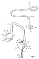
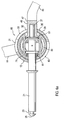
- Fig. 1 shows a schematic perspective view of a swivel frame frame lock with a substantially U-shaped connecting bracket 11.
- a connecting bracket 11 At one end of the connecting bracket 11 is a cylindrical Pot housing 13 a strap bearing device 15 attached, for example welded.
- a Pot housing 17 At the other end of the connecting bracket 11 is a Pot housing 17 a bracket receiving device 19 attached.
- a rod-like straight swivel bracket 21 pivotally mounted.
- the free end of the Swivel bracket 21 has a beveled on the front, by a circumferential locking groove 23 remote ironing head 25.
- the bracket bearing means 15 forms the Swivel bracket 21 with a pin-shaped axial extension section a handle 27.
- the handle 27 protrudes from the pot housing 13 through a keyhole-shaped recess on the side wall 29 of the pot housing 13 out, this recess is a substantially round Removal opening 31 and an adjoining, narrower Slit receptacle 33 has.
- the side wall 29 of the pot housing 13th forms an Schugreifungsabexcellent in the vicinity of the slot receptacle 33 35, as will be explained below.
- Lock cylinder 37 At the front of the bow receiving device 19 is the front a concentric with the longitudinal axis of the pot housing 17 is arranged Lock cylinder 37 to recognize.
- the hollow cylindrical side wall 39 of the Pot housing 17 has a bracket bearing device 15 facing Bow receiving opening 41.
- Fig. 1 further shows a safety rope 45, which at one end a Seilkloben 47 with a neck portion 49 and a subsequent thereto Backup collar 51 has.
- the cable clamp 47 is hollow, with a receiving opening 53 on the front side (dashed lines in Fig. 1) ) Located.
- the other end of the safety rope 45 is as a Loop 55 formed.
- Fig. 2 shows the state thus achieved.
- the safety rope 45 forms with the loop 55 a loop 61 which engages around a lamp post 63.
- the cable clamp 47 is connected to the safety collar 51 within the Slit holder 33 of the bracket bearing device 15 caught.
- the swivel bracket 21 is in the horizontal closed position and is at the Ironing device 19 locked. The two-wheeler is thus secured twice against theft.
- the illustrated security system offers the advantage of being able to Securing the safety rope 45 to the frame lock by low Structural effort is created, in addition to the required anyway Handle 27 essentially only the removal opening 31 and the slot receptacle 33 on the strap bearing device 15 are required. Above all, the handling of the security system is very simple and comfortable, because the user with the same hand only the rope block 47 must attach to the handle 27 and then the Seilkloben 47 together with the handle 27 pivot and move axially can, at the same time a final locking of the pivot bracket 21st and securing the safety rope 45. It is also for the user readily apparent whether the safety rope 45 with the Seilkloben 47 is actually reliably secured to the frame lock.
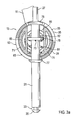
- FIG. 3a shows the strap bearing device 15 in a cross-sectional view.
- the two half-shells 71 are within the pot housing 13 to a central axis of rotation 73 rotatably mounted, so that the swivel bracket 21st is mounted pivotably in addition to the axial displacement.
- the swivel bracket 21 and the handle 27 are integrally rotationally symmetrical manufactured as a hardened turned part.
- the swivel bracket 21 has an outer stop collar 75 at the transition to the handle 27, an inner stop collar 77 and an intermediate middle stop collar 79.
- the swivel bracket 21 is by means of a compression spring 81 biased axially in the direction of the handle 27 carrying end, wherein the compression spring 81 on the one hand to the half-shells 71st and on the other supported on the middle stop collar 79.
- the Compression spring 81 thus biases the swivel bracket 21 in a in Fig. 3a shown axial basic position.
- the axial movement of the swivel bracket 21 along the biasing direction is by means of the inner stop collar 77 limited, which rests against the side wall 29 of the pot housing 13, and by means of the middle stop collar 79, which at a boundary collar 82 of the half-shells 71 rests.
- a Spiral spring 85 to recognize the pivot bracket 21 in the shown biased vertical release position.
- a blocking device against an unintentional pivoting movement secured from the illustrated release position.
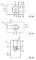
- This blocking device is on the part of the bracket bearing device 15 by blocking sections 87 of the side wall 29 of the pot housing 13 formed, the transition between the removal opening 31 and the slot receiving 33 limit (Fig. 3b).
- At these blocking portions 87 is namely the outer Stop collar 75 of the swivel bracket 21, for the explained blocking function thus acts as a counter element.
- FIG. 3b shows a top view of the strap bearing device 15 according to FIG Fig. 3a, in particular the handle 27 with the adjoining thereto outer stop collar 75 of the swivel bracket 21 and the Slit recording 33 can be seen.
- the outer stop collar 75 at the blocking portions 87 of Side wall 29 abuts.
- Fig. 3c shows a bottom view of the bracket bearing device 15 according to Fig. 3a, in particular of the swivel bracket 21 with the inner Stop collar 77 and the guide slot 83 on the side wall 29 to recognize.
- Fig. 4 shows the bracket bearing device 15 in one of Fig. 3a corresponding Cross-sectional view, now with the cable clamp 47 of the safety rope 45 is placed on the handle 27, thus in the receiving opening 53 of the Seilklobens 47 protrudes.
- the swivel bracket 27 by means of Seilklobens 47 already against the pressure of the compression spring 81 has been slightly shifted axially, so that on the outer Stop collar 75 of the swivel bracket 21 congruent patch Safety collar 51 of Seilklobens 47 now exactly within the side wall 29 of the pot housing 23 is arranged.
- the explained blockade of Swivel bracket 21 against unintentional pivoting movement thus overcome.
- the swivel bracket 21 now takes an axial Panning position, while still in the vertical release position located.
- Fig. 5a shows the state thus achieved.
- the swivel bracket 21 is located continue to be in the axial pivot position, i. the security bond 51 of the Seilklobens 47 is located exactly within the side wall 29th of the pot housing 13.
- the cable clamp 47 is now against axial removal secured from the strap bearing device 15, since the neck portion 49 of the Seilklobens 47 now no longer from the removal opening 31, but is surrounded by the narrower slot receptacle 33 and the Schugreifungsabêt 35 of the side wall 29, the safety collar 51st thus engages behind.
- FIG. 5b shows the strap bearing device 15 according to FIG. 5a in a side cross-sectional view along a through the cable clamp 47 extending Level.
- Fig. 6a shows the axial locking position achieved thereby Swivel bracket 21.
- the cable clamp 47 is through the Schugreifungsabêt 35 of the side wall 29 continue against axial removal of the handle 27 secured. Now also the pivot bracket 21 locked and thus against pivoting back into the vertical release position is secured, the patch on the handle 27 Seilkloben 47 also not be guided laterally from the slot receiving 33.
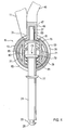
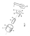
- Fig. 7 illustrates in a simplified exploded view of the structure the locking mechanism of the bracket receiving means 19 for Locking the swivel bracket 21. Shown is the substantially hollow cylindrical Pot housing 17 with the side bracket receiving opening 41st Further, the lock cylinder 37 is shown, on its rear end side a driver element 91 has.
- Fig. 7 also shows a turning bolt 93 made of hardened steel.
- This has a base plate 95 with a central coupling recess 97 for direct or indirect coupling with the driver 91 of the Locking cylinder 37.
- the rotary latch 93 has a on the base plate 95 laterally molded latch portion 99, the arched such is that he is in the space between the lock cylinder 37 and the pot housing 17 can be used.
- the rotary latch 93 has a connecting tongue 101 for coupling with a tension spring (in Fig. 7 not shown).
- Fig. 7 shows a rear side wall 103, on which the connecting bracket 11 is attached.
- the pot housing 17 also integrally with the Rear side wall 103 may be formed.
- Fig. 5c shows in a simplified cross-sectional view of the bracket receiving device 19 and the free end of the pivot bracket 21 in the Condition of the bracket bearing device 15 of FIG. 5a and 5b, wherein the Swivel bracket 21, although already in the closed position, but still in the axial pivot position is located.
- the ironing head reaches 25 just until just before the hanger receiving opening 41 of Ironing device 19.
- the rotary latch 93 is by means of a at the Connecting tongue 101 attacking tension spring 105 such biased that the latch portion 99, the bracket receiving opening 41 inside partially hidden.
- Fig. 6b shows in a further cross-sectional view thus achieved Condition, the state of the bracket bearing device shown in Fig. 6a 15 corresponds.
- the swivel bracket 21 is now in the axial Locking position, wherein the ironing head 25 of the locking portion 99th of the rotary latch 93 is partially engaged behind.
- the swivel bracket 21 is thus against axial removal from the hanger receiving opening 41st secured, wherein the locking portion 99 in particular by the side wall Protected 39 of the pot housing 17 against manipulation from the outside is.
- the illustrated snap mechanism of the rotary latch 93 is not mandatory.
- the rotary latch 93 can Alternatively coupled by forced operation with the lock cylinder 37 be. It is essential that within the bracket receiving device 19 only the locking mechanism is housed. this makes possible a central arrangement of the lock cylinder 37 and thus the Use of a rotatably bekampfeerten rotary latch 93. This protects the Frame lock against unauthorized unlocking on the principle of "Shock opening".
- the made of hardened steel Base plate 95 a particularly effective protection of the back Front side of the lock cylinder against departure or other manipulation attempts.
- FIGS. 1 to 7 To the embodiment of FIGS. 1 to 7 is also to be noted, that the indirect attachment of the bracket bearing device 15 and the Ironing device 19 on the bicycle frame by means of the connecting bracket 11 is not mandatory and typically at the retrofit is used. Alternatively, it is possible to choose the appropriate ones Pot housing 13, 17 - especially in the original equipment of the two-wheeler - to connect directly to the bicycle frame.
- FIG. 8 shows a cross-sectional view corresponding to FIG. 5a Cross-sectional view of part of an alternative embodiment of the Strap bearing device 15 and the safety rope 45.
- the cable clamp 47 is also via a removal opening 31 on the side wall 29 of the pot housing 13 laterally in a Slot receptacle 33 introduced so that a slot receiving 33 surrounding Schugreifungsabexcellent 35 of the side wall 29 a Sich ceremoniessbund 51 of the cable clamp 47 engages behind.
- the cable clamp 47 does not open the handle 27 attached. Instead, the Seilkloben 47 first inserted laterally into the slot receiving 33 before the handle 27th by separate pivoting operation from a vertical release position is transferred to a horizontal closed position in which they the rope clamp 47 blocked against a lateral removal from the slot receptacle 33.
- bracket bearing device 15 of this embodiment can correspond to the structure explained with reference to FIGS. 3 to 7. Especially can an axial displaceability of the pivot bracket 21 and the handle 27 may be provided.
Landscapes
- Engineering & Computer Science (AREA)
- Mechanical Engineering (AREA)
- Lock And Its Accessories (AREA)
- Steering Devices For Bicycles And Motorcycles (AREA)
Applications Claiming Priority (2)
| Application Number | Priority Date | Filing Date | Title |
|---|---|---|---|
| DE10358300 | 2003-12-12 | ||
| DE10358300.9A DE10358300B4 (de) | 2003-12-12 | 2003-12-12 | Schwenkbügel-Rahmenschloss, Verwendung eines Schwenkbügel-Rahmenschlosses und Zweirad-Sicherungssystem mit einem Schwenkbügel-Rahmenschloss und einem Sicherungsseil |
Publications (3)
| Publication Number | Publication Date |
|---|---|
| EP1548216A2 true EP1548216A2 (fr) | 2005-06-29 |
| EP1548216A3 EP1548216A3 (fr) | 2007-03-14 |
| EP1548216B1 EP1548216B1 (fr) | 2011-08-24 |
Family
ID=34530331
Family Applications (1)
| Application Number | Title | Priority Date | Filing Date |
|---|---|---|---|
| EP04026600A Expired - Lifetime EP1548216B1 (fr) | 2003-12-12 | 2004-11-09 | Système de verrouillage pour bicyclette avec une serrure d'encerclement à anse pivotante et une corde de sécurité |
Country Status (5)
| Country | Link |
|---|---|
| EP (1) | EP1548216B1 (fr) |
| CN (1) | CN1626762B (fr) |
| AT (1) | ATE521774T1 (fr) |
| DE (1) | DE10358300B4 (fr) |
| DK (1) | DK1548216T3 (fr) |
Cited By (2)
| Publication number | Priority date | Publication date | Assignee | Title |
|---|---|---|---|---|
| EP2450269A4 (fr) * | 2009-07-01 | 2012-11-14 | Componentes Europ Moto Auto S L | Dispositif antivol pour motocyclettes, quads, scooters et analogues |
| WO2019183571A1 (fr) | 2018-03-23 | 2019-09-26 | Uber Technologies, Inc. | Ensemble de verrou pour fixer un véhicule à roues |
Families Citing this family (7)
| Publication number | Priority date | Publication date | Assignee | Title |
|---|---|---|---|---|
| DE102011015313A1 (de) | 2011-03-29 | 2012-10-04 | ABUS August Bremicker Söhne KG | Rahmenschloss |
| CN106945821A (zh) * | 2017-04-18 | 2017-07-14 | 河北天启通宇航空器材科技发展有限公司 | 用于飞机的操纵杆位置锁紧装置及飞机 |
| CN109763725A (zh) * | 2017-11-09 | 2019-05-17 | 比亚迪股份有限公司 | 锁及共享单车 |
| DE102018111311A1 (de) | 2018-05-11 | 2019-11-14 | ABUS August Bremicker Söhne KG | Rahmenschlosssystem für ein Zweirad |
| DE102021114428B4 (de) | 2021-06-04 | 2023-01-12 | ABUS August Bremicker Söhne Kommanditgesellschaft | Messvorrichtung zum Ausmessen des Hinterbaus eines Zweirads |
| DE102021125310A1 (de) | 2021-09-29 | 2023-03-30 | ABUS August Bremicker Söhne Kommanditgesellschaft | Bügelschloss |
| DE102022111846A1 (de) | 2022-05-11 | 2023-11-16 | ABUS August Bremicker Söhne Kommanditgesellschaft | Bügelschloss mit Aufschweißpanzerung |
Citations (3)
| Publication number | Priority date | Publication date | Assignee | Title |
|---|---|---|---|---|
| WO1983004009A1 (fr) | 1982-05-06 | 1983-11-24 | BASTA LA^oSEFABRIK A/S | Verrou pour bicyclette |
| WO1990002074A1 (fr) | 1988-08-18 | 1990-03-08 | Basta Låsefabrik A/S | Cadenas pour bicyclettes |
| JP2001001967A (ja) | 1999-06-23 | 2001-01-09 | Munetaka:Kk | 二輪車錠 |
Family Cites Families (4)
| Publication number | Priority date | Publication date | Assignee | Title |
|---|---|---|---|---|
| NL8300423A (nl) * | 1983-02-04 | 1984-09-03 | Chubb Lips Nederland Bv | Tweewielerslot. |
| IT1294495B1 (it) * | 1995-11-15 | 1999-04-12 | Aprilia Spa | Antifurto per veicoli a due ruote. |
| CN2522557Y (zh) * | 2002-02-08 | 2002-11-27 | 胡芳雄 | 自行车锁装置改良 |
| DE10250961A1 (de) * | 2002-11-01 | 2004-05-13 | ABUS August Bremicker Söhne KG | Rahmenschloss |
-
2003
- 2003-12-12 DE DE10358300.9A patent/DE10358300B4/de not_active Expired - Fee Related
-
2004
- 2004-11-09 DK DK04026600.9T patent/DK1548216T3/da active
- 2004-11-09 AT AT04026600T patent/ATE521774T1/de active
- 2004-11-09 EP EP04026600A patent/EP1548216B1/fr not_active Expired - Lifetime
- 2004-12-02 CN CN200410095574.8A patent/CN1626762B/zh not_active Expired - Fee Related
Patent Citations (3)
| Publication number | Priority date | Publication date | Assignee | Title |
|---|---|---|---|---|
| WO1983004009A1 (fr) | 1982-05-06 | 1983-11-24 | BASTA LA^oSEFABRIK A/S | Verrou pour bicyclette |
| WO1990002074A1 (fr) | 1988-08-18 | 1990-03-08 | Basta Låsefabrik A/S | Cadenas pour bicyclettes |
| JP2001001967A (ja) | 1999-06-23 | 2001-01-09 | Munetaka:Kk | 二輪車錠 |
Cited By (4)
| Publication number | Priority date | Publication date | Assignee | Title |
|---|---|---|---|---|
| EP2450269A4 (fr) * | 2009-07-01 | 2012-11-14 | Componentes Europ Moto Auto S L | Dispositif antivol pour motocyclettes, quads, scooters et analogues |
| WO2019183571A1 (fr) | 2018-03-23 | 2019-09-26 | Uber Technologies, Inc. | Ensemble de verrou pour fixer un véhicule à roues |
| EP3768582A4 (fr) * | 2018-03-23 | 2022-01-12 | Neutron Holdings, Inc., DBA Lime | Ensemble de verrou pour fixer un véhicule à roues |
| US11268303B2 (en) | 2018-03-23 | 2022-03-08 | Neutron Holdings, Inc. | Lock assembly for securing a wheeled vehicle |
Also Published As
| Publication number | Publication date |
|---|---|
| DK1548216T3 (da) | 2011-12-12 |
| EP1548216B1 (fr) | 2011-08-24 |
| CN1626762B (zh) | 2010-10-27 |
| DE10358300A1 (de) | 2005-07-14 |
| ATE521774T1 (de) | 2011-09-15 |
| EP1548216A3 (fr) | 2007-03-14 |
| CN1626762A (zh) | 2005-06-15 |
| DE10358300B4 (de) | 2014-02-20 |
Similar Documents
| Publication | Publication Date | Title |
|---|---|---|
| DE102005040066B4 (de) | Gelenkschloss | |
| DE69018254T2 (de) | Verbessertes Fahrradschloss. | |
| EP2019178B1 (fr) | Serrure à barres articulées | |
| EP2020474B1 (fr) | Serrure | |
| EP2267256B1 (fr) | Cadenas | |
| EP1418302B1 (fr) | Serrure d'encerclement | |
| DE69925591T2 (de) | Bügelschloss mit auswechselbarem Schliessmechanismus | |
| EP3741932B1 (fr) | Verrou d'aiguille à articulation | |
| DE7813138U1 (de) | Schloß für ein Fahrrad od. dgl. mit Befestigungsteil | |
| US4920772A (en) | Bicycle lock | |
| DE102010008054B4 (de) | Zweirad-Schloss | |
| EP1548216B1 (fr) | Système de verrouillage pour bicyclette avec une serrure d'encerclement à anse pivotante et une corde de sécurité | |
| DE3034750A1 (de) | Vorrichtung zur sicherung eines fahrradrahmens an einem dachtraeger auf einem kraftfahrzeug | |
| EP0541736B1 (fr) | Moyeu a serrage rapide pour bicyclettes | |
| DE202014006369U1 (de) | Ringbügelschloss | |
| EP1416110B1 (fr) | Serrure d'encerclement pour deux roues | |
| DE4306562C2 (de) | Getriebeschloß für Fahrräder | |
| DE102005063514B4 (de) | Gelenkschloss | |
| DE4310590A1 (de) | Anschließvorrichtung zum Anschließen wenigstens eines Teiles eines Fahrrades | |
| EP0725003B1 (fr) | Véhicule, en particulier véhicule à deux roues avec serrure de câble associée | |
| EP4200502B1 (fr) | Cadenas portatif | |
| DE4142507A1 (de) | Schnellspannabe fuer fahrraeder | |
| DE3104436C2 (de) | Schwenkbügelschloß für ein Fahrzeug, insbesondere ein Zweiradfahrzeug | |
| DE202005021748U1 (de) | Gelenkschloss | |
| DE10139105C1 (de) | Zahlenrohrschloß zur Diebstahlsicherung für Tretkurbel angetriebene Fahrzeuge |
Legal Events
| Date | Code | Title | Description |
|---|---|---|---|
| PUAI | Public reference made under article 153(3) epc to a published international application that has entered the european phase |
Free format text: ORIGINAL CODE: 0009012 |
|
| AK | Designated contracting states |
Kind code of ref document: A2 Designated state(s): AT BE BG CH CY CZ DE DK EE ES FI FR GB GR HU IE IS IT LI LU MC NL PL PT RO SE SI SK TR |
|
| AX | Request for extension of the european patent |
Extension state: AL HR LT LV MK YU |
|
| PUAL | Search report despatched |
Free format text: ORIGINAL CODE: 0009013 |
|
| AK | Designated contracting states |
Kind code of ref document: A3 Designated state(s): AT BE BG CH CY CZ DE DK EE ES FI FR GB GR HU IE IS IT LI LU MC NL PL PT RO SE SI SK TR |
|
| AX | Request for extension of the european patent |
Extension state: AL HR LT LV MK YU |
|
| 17P | Request for examination filed |
Effective date: 20070713 |
|
| AKX | Designation fees paid |
Designated state(s): AT BE BG CH CY CZ DE DK EE ES FI FR GB GR HU IE IS IT LI LU MC NL PL PT RO SE SI SK TR |
|
| 17Q | First examination report despatched |
Effective date: 20080418 |
|
| GRAP | Despatch of communication of intention to grant a patent |
Free format text: ORIGINAL CODE: EPIDOSNIGR1 |
|
| RTI1 | Title (correction) |
Free format text: LOCKING SYSTEM FOR A BICYCLE WITH A FRAME LOCK WITH PIVOTABLE SHACKLE AND A SECURITY CABLE |
|
| GRAS | Grant fee paid |
Free format text: ORIGINAL CODE: EPIDOSNIGR3 |
|
| GRAA | (expected) grant |
Free format text: ORIGINAL CODE: 0009210 |
|
| AK | Designated contracting states |
Kind code of ref document: B1 Designated state(s): AT BE BG CH CY CZ DE DK EE ES FI FR GB GR HU IE IS IT LI LU MC NL PL PT RO SE SI SK TR |
|
| REG | Reference to a national code |
Ref country code: GB Ref legal event code: FG4D Free format text: NOT ENGLISH |
|
| REG | Reference to a national code |
Ref country code: CH Ref legal event code: EP |
|
| REG | Reference to a national code |
Ref country code: IE Ref legal event code: FG4D Free format text: LANGUAGE OF EP DOCUMENT: GERMAN |
|
| REG | Reference to a national code |
Ref country code: DE Ref legal event code: R096 Ref document number: 502004012815 Country of ref document: DE Effective date: 20111027 |
|
| REG | Reference to a national code |
Ref country code: DK Ref legal event code: T3 |
|
| REG | Reference to a national code |
Ref country code: NL Ref legal event code: VDEP Effective date: 20110824 |
|
| PG25 | Lapsed in a contracting state [announced via postgrant information from national office to epo] |
Ref country code: SE Free format text: LAPSE BECAUSE OF FAILURE TO SUBMIT A TRANSLATION OF THE DESCRIPTION OR TO PAY THE FEE WITHIN THE PRESCRIBED TIME-LIMIT Effective date: 20110824 Ref country code: IS Free format text: LAPSE BECAUSE OF FAILURE TO SUBMIT A TRANSLATION OF THE DESCRIPTION OR TO PAY THE FEE WITHIN THE PRESCRIBED TIME-LIMIT Effective date: 20111224 Ref country code: FI Free format text: LAPSE BECAUSE OF FAILURE TO SUBMIT A TRANSLATION OF THE DESCRIPTION OR TO PAY THE FEE WITHIN THE PRESCRIBED TIME-LIMIT Effective date: 20110824 Ref country code: NL Free format text: LAPSE BECAUSE OF FAILURE TO SUBMIT A TRANSLATION OF THE DESCRIPTION OR TO PAY THE FEE WITHIN THE PRESCRIBED TIME-LIMIT Effective date: 20110824 Ref country code: PT Free format text: LAPSE BECAUSE OF FAILURE TO SUBMIT A TRANSLATION OF THE DESCRIPTION OR TO PAY THE FEE WITHIN THE PRESCRIBED TIME-LIMIT Effective date: 20111226 |
|
| PG25 | Lapsed in a contracting state [announced via postgrant information from national office to epo] |
Ref country code: CY Free format text: LAPSE BECAUSE OF FAILURE TO SUBMIT A TRANSLATION OF THE DESCRIPTION OR TO PAY THE FEE WITHIN THE PRESCRIBED TIME-LIMIT Effective date: 20110824 Ref country code: SI Free format text: LAPSE BECAUSE OF FAILURE TO SUBMIT A TRANSLATION OF THE DESCRIPTION OR TO PAY THE FEE WITHIN THE PRESCRIBED TIME-LIMIT Effective date: 20110824 Ref country code: PL Free format text: LAPSE BECAUSE OF FAILURE TO SUBMIT A TRANSLATION OF THE DESCRIPTION OR TO PAY THE FEE WITHIN THE PRESCRIBED TIME-LIMIT Effective date: 20110824 |
|
| REG | Reference to a national code |
Ref country code: IE Ref legal event code: FD4D |
|
| PG25 | Lapsed in a contracting state [announced via postgrant information from national office to epo] |
Ref country code: IE Free format text: LAPSE BECAUSE OF FAILURE TO SUBMIT A TRANSLATION OF THE DESCRIPTION OR TO PAY THE FEE WITHIN THE PRESCRIBED TIME-LIMIT Effective date: 20110824 Ref country code: CZ Free format text: LAPSE BECAUSE OF FAILURE TO SUBMIT A TRANSLATION OF THE DESCRIPTION OR TO PAY THE FEE WITHIN THE PRESCRIBED TIME-LIMIT Effective date: 20110824 Ref country code: SK Free format text: LAPSE BECAUSE OF FAILURE TO SUBMIT A TRANSLATION OF THE DESCRIPTION OR TO PAY THE FEE WITHIN THE PRESCRIBED TIME-LIMIT Effective date: 20110824 |
|
| BERE | Be: lapsed |
Owner name: ABUS AUGUST BREMICKER SOHNE K.G. Effective date: 20111130 |
|
| PG25 | Lapsed in a contracting state [announced via postgrant information from national office to epo] |
Ref country code: IT Free format text: LAPSE BECAUSE OF FAILURE TO SUBMIT A TRANSLATION OF THE DESCRIPTION OR TO PAY THE FEE WITHIN THE PRESCRIBED TIME-LIMIT Effective date: 20110824 Ref country code: EE Free format text: LAPSE BECAUSE OF FAILURE TO SUBMIT A TRANSLATION OF THE DESCRIPTION OR TO PAY THE FEE WITHIN THE PRESCRIBED TIME-LIMIT Effective date: 20110824 Ref country code: RO Free format text: LAPSE BECAUSE OF FAILURE TO SUBMIT A TRANSLATION OF THE DESCRIPTION OR TO PAY THE FEE WITHIN THE PRESCRIBED TIME-LIMIT Effective date: 20110824 |
|
| PG25 | Lapsed in a contracting state [announced via postgrant information from national office to epo] |
Ref country code: MC Free format text: LAPSE BECAUSE OF NON-PAYMENT OF DUE FEES Effective date: 20111130 |
|
| PLBE | No opposition filed within time limit |
Free format text: ORIGINAL CODE: 0009261 |
|
| REG | Reference to a national code |
Ref country code: CH Ref legal event code: PL |
|
| STAA | Information on the status of an ep patent application or granted ep patent |
Free format text: STATUS: NO OPPOSITION FILED WITHIN TIME LIMIT |
|
| GBPC | Gb: european patent ceased through non-payment of renewal fee |
Effective date: 20111124 |
|
| PG25 | Lapsed in a contracting state [announced via postgrant information from national office to epo] |
Ref country code: CH Free format text: LAPSE BECAUSE OF NON-PAYMENT OF DUE FEES Effective date: 20111130 Ref country code: LI Free format text: LAPSE BECAUSE OF NON-PAYMENT OF DUE FEES Effective date: 20111130 |
|
| 26N | No opposition filed |
Effective date: 20120525 |
|
| REG | Reference to a national code |
Ref country code: FR Ref legal event code: ST Effective date: 20120731 |
|
| PG25 | Lapsed in a contracting state [announced via postgrant information from national office to epo] |
Ref country code: BE Free format text: LAPSE BECAUSE OF NON-PAYMENT OF DUE FEES Effective date: 20111130 |
|
| REG | Reference to a national code |
Ref country code: DE Ref legal event code: R097 Ref document number: 502004012815 Country of ref document: DE Effective date: 20120525 |
|
| PG25 | Lapsed in a contracting state [announced via postgrant information from national office to epo] |
Ref country code: GB Free format text: LAPSE BECAUSE OF NON-PAYMENT OF DUE FEES Effective date: 20111124 |
|
| PG25 | Lapsed in a contracting state [announced via postgrant information from national office to epo] |
Ref country code: FR Free format text: LAPSE BECAUSE OF NON-PAYMENT OF DUE FEES Effective date: 20111130 |
|
| REG | Reference to a national code |
Ref country code: AT Ref legal event code: MM01 Ref document number: 521774 Country of ref document: AT Kind code of ref document: T Effective date: 20111109 |
|
| PG25 | Lapsed in a contracting state [announced via postgrant information from national office to epo] |
Ref country code: AT Free format text: LAPSE BECAUSE OF NON-PAYMENT OF DUE FEES Effective date: 20111109 |
|
| PG25 | Lapsed in a contracting state [announced via postgrant information from national office to epo] |
Ref country code: ES Free format text: LAPSE BECAUSE OF FAILURE TO SUBMIT A TRANSLATION OF THE DESCRIPTION OR TO PAY THE FEE WITHIN THE PRESCRIBED TIME-LIMIT Effective date: 20111205 |
|
| PG25 | Lapsed in a contracting state [announced via postgrant information from national office to epo] |
Ref country code: LU Free format text: LAPSE BECAUSE OF NON-PAYMENT OF DUE FEES Effective date: 20111109 |
|
| PG25 | Lapsed in a contracting state [announced via postgrant information from national office to epo] |
Ref country code: BG Free format text: LAPSE BECAUSE OF FAILURE TO SUBMIT A TRANSLATION OF THE DESCRIPTION OR TO PAY THE FEE WITHIN THE PRESCRIBED TIME-LIMIT Effective date: 20111124 |
|
| PG25 | Lapsed in a contracting state [announced via postgrant information from national office to epo] |
Ref country code: TR Free format text: LAPSE BECAUSE OF FAILURE TO SUBMIT A TRANSLATION OF THE DESCRIPTION OR TO PAY THE FEE WITHIN THE PRESCRIBED TIME-LIMIT Effective date: 20110824 |
|
| PG25 | Lapsed in a contracting state [announced via postgrant information from national office to epo] |
Ref country code: HU Free format text: LAPSE BECAUSE OF FAILURE TO SUBMIT A TRANSLATION OF THE DESCRIPTION OR TO PAY THE FEE WITHIN THE PRESCRIBED TIME-LIMIT Effective date: 20110824 |
|
| PG25 | Lapsed in a contracting state [announced via postgrant information from national office to epo] |
Ref country code: GR Free format text: LAPSE BECAUSE OF FAILURE TO SUBMIT A TRANSLATION OF THE DESCRIPTION OR TO PAY THE FEE WITHIN THE PRESCRIBED TIME-LIMIT Effective date: 20110824 |
|
| PGFP | Annual fee paid to national office [announced via postgrant information from national office to epo] |
Ref country code: DK Payment date: 20181122 Year of fee payment: 15 |
|
| PGFP | Annual fee paid to national office [announced via postgrant information from national office to epo] |
Ref country code: DE Payment date: 20190130 Year of fee payment: 15 |
|
| REG | Reference to a national code |
Ref country code: DE Ref legal event code: R119 Ref document number: 502004012815 Country of ref document: DE |
|
| REG | Reference to a national code |
Ref country code: DK Ref legal event code: EBP Effective date: 20191130 |
|
| PG25 | Lapsed in a contracting state [announced via postgrant information from national office to epo] |
Ref country code: DE Free format text: LAPSE BECAUSE OF NON-PAYMENT OF DUE FEES Effective date: 20200603 Ref country code: DK Free format text: LAPSE BECAUSE OF NON-PAYMENT OF DUE FEES Effective date: 20191130 |