EP1548200A2 - Façade avec montants et traverses - Google Patents
Façade avec montants et traverses Download PDFInfo
- Publication number
- EP1548200A2 EP1548200A2 EP04030614A EP04030614A EP1548200A2 EP 1548200 A2 EP1548200 A2 EP 1548200A2 EP 04030614 A EP04030614 A EP 04030614A EP 04030614 A EP04030614 A EP 04030614A EP 1548200 A2 EP1548200 A2 EP 1548200A2
- Authority
- EP
- European Patent Office
- Prior art keywords
- post
- parts
- channel
- profile
- clamping element
- Prior art date
- Legal status (The legal status is an assumption and is not a legal conclusion. Google has not performed a legal analysis and makes no representation as to the accuracy of the status listed.)
- Granted
Links
- 230000002787 reinforcement Effects 0.000 claims abstract description 5
- 239000011521 glass Substances 0.000 claims abstract description 3
- 239000003351 stiffener Substances 0.000 claims description 33
- 239000006228 supernatant Substances 0.000 claims description 29
- 230000000694 effects Effects 0.000 claims description 11
- 229910052751 metal Inorganic materials 0.000 claims description 10
- 239000002184 metal Substances 0.000 claims description 10
- 239000002023 wood Substances 0.000 claims description 7
- 238000001125 extrusion Methods 0.000 claims description 6
- 238000003780 insertion Methods 0.000 claims description 6
- 230000037431 insertion Effects 0.000 claims description 6
- 239000004033 plastic Substances 0.000 claims description 6
- 229920003023 plastic Polymers 0.000 claims description 6
- 238000009434 installation Methods 0.000 claims description 4
- 239000000463 material Substances 0.000 claims description 4
- 229920002430 Fibre-reinforced plastic Polymers 0.000 claims description 2
- 239000011151 fibre-reinforced plastic Substances 0.000 claims description 2
- 210000003195 fascia Anatomy 0.000 abstract 2
- 238000009413 insulation Methods 0.000 abstract 1
- 210000002414 leg Anatomy 0.000 description 30
- 238000013461 design Methods 0.000 description 9
- 229910052782 aluminium Inorganic materials 0.000 description 7
- XAGFODPZIPBFFR-UHFFFAOYSA-N aluminium Chemical compound [Al] XAGFODPZIPBFFR-UHFFFAOYSA-N 0.000 description 7
- 238000010276 construction Methods 0.000 description 6
- 238000000034 method Methods 0.000 description 5
- 230000008569 process Effects 0.000 description 4
- XEEYBQQBJWHFJM-UHFFFAOYSA-N Iron Chemical compound [Fe] XEEYBQQBJWHFJM-UHFFFAOYSA-N 0.000 description 3
- 230000008901 benefit Effects 0.000 description 3
- 239000002131 composite material Substances 0.000 description 3
- 230000002349 favourable effect Effects 0.000 description 3
- 238000012549 training Methods 0.000 description 3
- 210000000689 upper leg Anatomy 0.000 description 3
- 230000007423 decrease Effects 0.000 description 2
- 230000001419 dependent effect Effects 0.000 description 2
- 238000009472 formulation Methods 0.000 description 2
- 238000004519 manufacturing process Methods 0.000 description 2
- 239000000203 mixture Substances 0.000 description 2
- CWYNVVGOOAEACU-UHFFFAOYSA-N Fe2+ Chemical compound [Fe+2] CWYNVVGOOAEACU-UHFFFAOYSA-N 0.000 description 1
- 229910000831 Steel Inorganic materials 0.000 description 1
- 229910000754 Wrought iron Inorganic materials 0.000 description 1
- 238000010521 absorption reaction Methods 0.000 description 1
- 230000009471 action Effects 0.000 description 1
- AZDRQVAHHNSJOQ-UHFFFAOYSA-N alumane Chemical group [AlH3] AZDRQVAHHNSJOQ-UHFFFAOYSA-N 0.000 description 1
- 238000005452 bending Methods 0.000 description 1
- 150000001875 compounds Chemical class 0.000 description 1
- 238000011161 development Methods 0.000 description 1
- 238000009826 distribution Methods 0.000 description 1
- 238000005242 forging Methods 0.000 description 1
- 230000001771 impaired effect Effects 0.000 description 1
- 230000006872 improvement Effects 0.000 description 1
- 230000003993 interaction Effects 0.000 description 1
- 229910052742 iron Inorganic materials 0.000 description 1
- JEIPFZHSYJVQDO-UHFFFAOYSA-N iron(III) oxide Inorganic materials O=[Fe]O[Fe]=O JEIPFZHSYJVQDO-UHFFFAOYSA-N 0.000 description 1
- 150000002739 metals Chemical class 0.000 description 1
- 238000002360 preparation method Methods 0.000 description 1
- 238000003825 pressing Methods 0.000 description 1
- 238000012545 processing Methods 0.000 description 1
- 238000010079 rubber tapping Methods 0.000 description 1
- 238000003892 spreading Methods 0.000 description 1
- 230000007480 spreading Effects 0.000 description 1
- 239000010959 steel Substances 0.000 description 1
- 239000010902 straw Substances 0.000 description 1
- 238000012546 transfer Methods 0.000 description 1
- 230000009466 transformation Effects 0.000 description 1
Images


Classifications
-
- E—FIXED CONSTRUCTIONS
- E04—BUILDING
- E04B—GENERAL BUILDING CONSTRUCTIONS; WALLS, e.g. PARTITIONS; ROOFS; FLOORS; CEILINGS; INSULATION OR OTHER PROTECTION OF BUILDINGS
- E04B2/00—Walls, e.g. partitions, for buildings; Wall construction with regard to insulation; Connections specially adapted to walls
- E04B2/88—Curtain walls
- E04B2/96—Curtain walls comprising panels attached to the structure through mullions or transoms
- E04B2/965—Connections of mullions and transoms
Definitions
- the invention relates to a mullion and transom façade accordingly the preamble of claim 1.
- mullion-transom facades is a substantially vertical or horizontally extending support profile provided. That the Façade elements bearing fastening profile is either pressed directly on the support profile or with appropriate Fasteners attached to this.
- the supporting profiles themselves consist of a metal, such as steel, aluminum or The like, however, for the facades and support profiles Used wood. Such facades are, for example, too referred to as wood aluminum facades.
- the invention has set itself the task of a mullion-transom façade, as described above, available too in which a stable and torsionally stiff Connection between the horizontal and vertical facade element consists.
- the invention is based on a Post and beam facade, as described above, and proposes before, that in the junction of posts and bars a bolt torsion-fixing, defining stiffening is provided.
- the proposal according to the invention is a stiffening on Node between pole and latch.
- the node is doing through those areas on the post or bar defined, which in the finished facade in operative connection stand or touch each other.
- the arrangement is according to of the invention chosen so that the stiffener in the post or Bar is integrated and so the design of the facade is not impaired.
- the proposal according to the invention is the Node stiffened so that even at a considerable Load of the bolt this distortion remains.
- the invention proposes a total of three variants, such as this can be achieved.
- the first variant how will be described below, two interacting with each other Parts suggested.
- the Stiffening of a profile projection of the arranged on the bolt Fastening profiles achieved, this profile projection then attached to the post accordingly and / or if necessary directly above the post or on top of the post Post arranged profile is able to remove the load.
- the two aforementioned Suggestions combined, which is even more significant Increasing the stiffening results.
- the stiffener consists of two parts which can be joined together, with a first part at the side of the post and a second part is arranged on the front side of the bolt. Plugging means in this context, the insertion of the two parts into each other and their longitudinal mobility as a sliding movement. Between the first and the second part is a channel formed, which preferably over the entire length of the part extends.
- the attached to the front side of the bolt part is according to an embodiment of the invention on the bolt front side placed. According to a further embodiment of the invention However, it is intended to sink the part in a recess. In this way, the front side of the bolt is directly at the post, although between the posts and bars the Reinforcement is located.
- the two-piece Design of the stiffener has the advantage that this easy to assemble and, for example, already on the workshop side can be prepared, reducing the assembly effort the construction site is shortened considerably.
- the inventive Arrangement also allows that the horizontally extending Riegel can be retrofitted into the facade. By the invention, therefore, for example, a transformation of Post and beam façade easily possible. This works even with existing facades, with corresponding Elements equipped to be supplemented.
- the arrangement of a Channel between the two parts serves to appropriate To include clamping elements and the like. Since preferably the parts are made as profiled goods, extends Conveniently, the channel also equal over the entire length of the part.
- Both parts are fixed by bracing against each other.
- the Bracing is advantageously carried out by means of a tensioning element that can be used in the channel formed by the parts or is screwed.
- a tensioning element that can be used in the channel formed by the parts or is screwed.
- the parts to each other at least during the attachment of the Riegels at the post, have a fitting-in game.
- This installation play of course facilitates the assembly of the Tie at the post.
- the installation play allows a certain Alignment of the two elements to each other in order to optimize this align and also compensate for certain dimensional tolerances. is but then the bolt is placed in the desired position on the post, so by the use of the clamping element, as described, eliminated this installation play and the two parts tightly clamped together.
- the cooperating Parts of several channels, each for receiving a tensioning element exhibit. It is sufficient in the first variant of the invention already off, with a clamping element success of the invention to realize. But are the parts that work together formed several channels, so it is of course favorable by increasing the number of tensioning clamping elements to achieve an improvement in stability.
- the invention thus comprises both solutions in which only one Clamping element is used, as well as solutions in which a variety of clamping elements (two or more) used become.
- the part attached to the post almost extends over the entire post width. In this way, a large contact surface achieved, reducing the strength of the mullion-transom facade is increased.
- the part attached to the post extends however, according to an embodiment of the invention, almost only about entire post width so that it fits well in a recess insert and is not necessarily visible from the outside. Correspondingly long is the part attached to the bolt, so that both parts intermesh over their full length.
- this invention includes both solutions, depending on the in which proportions posts and bars installed to each other become.
- the clamping element acts on at least two Channel areas on the parts spanning a. Preferably lie these areas in the front and rear channel area. This can done by two short pins or screws, by both Ends of the channel are introduced into the channel. From The clamping force is introduced in front and from behind. The bracing However, it can also be done by means of a pen, the extends over the entire length of the channel and the Clamping force over the entire length of the parts extends. By distributing the clamping force over the entire length of the parts There is no game that can make you wobble. By the Distribution of the clamping areas on the front and rear Channel area is, without the bracing over the entire Length takes place, but evenly distributed.
- At least one of the parts is substantially U-shaped.
- This U-shaped part substantially decreases positively the second part in itself.
- This second part may consist of a profile part whose cross section at least the width of the U corresponds, so that both legs of the U include the profile part between them.
- the thigh The U's lie directly on two opposing Outside of the profile part.
- the Latch characterized in that the profile part is received by the "U" do not twist.
- the second Part of the stiffener also from a U-profile, with the Legs of this U-profile with their outsides on the insides abut the leg of the first part.
- the second Part C-shaped that is, the ends of the legs of the U have inwardly directed bends.
- This C-shaped part surrounds with the bends at least partly the first part. In this way is the contact surface enlarged between the first and second part, whereby the torsional strength is increased. So that from the Legs angled ends - so the bends - the can embrace the first part is either the first part with attached to the bolt a certain distance, or it is provided an undercut, which absorb the bends.
- a part that has undercuts can have a T-shaped cross-section.
- the T is with his vertical foot attached to the post or latch, while the C-shaped Part of the crossbeam of the T absorbs.
- the crossbeam is dimensioned such that it with its end faces on the insides of the legs of the U or the C's positive fit.
- the bearing surface should be as possible be chosen large, so that when applying a torque to the Latch, in the stiffening no play exists and so the Power is dissipated over the post.
- the parts are formed so that one part of the respective completely absorbs the other part. This means, if both parts are inserted into each other, none of the Parts over the other. This will be a very compact design for the stiffener formed, which is fine between posts and bars accommodate or slightly in a recess is recessed on the front side of the bolt can be.
- the bends at the ends of the legs of the U are in hereinafter referred to as supernatants.
- the first part is U-shaped with provided at the ends of the legs supernatants formed, but, according to a variant of the invention, the second part is also U-shaped with the Ends of the legs provided on supernatants.
- the overhangs of one of the parts can be aligned towards each other be.
- the substantially C-shaped Training one of the parts formed.
- the supernatants are aligned away from each other.
- This projection limits the parts edge-like. At the first Part is the edge to the outside and the second part inside directed.
- An essential feature of a variant according to the invention consists in that the end overhang of the first part opposite the end-side projection of the second part is aligned. In this way it is possible that the two Supernatants interact with each other. The two parts are bordered by the supernatants.
- the two parts By means of a sliding movement along its longitudinal axis the two parts are engaged with each other. A movement perpendicular to the longitudinal axis is thus locked out. Both parts are holding together. These Bracket is sufficient to lock the latch opposite the jamb Fasten.
- the two parts are designed in such a way that the outer dimension of the first part to fit in the inner dimension the leg of the second part sits. In this way results a torsion-free connection between posts and Bars.
- the contact surfaces are at spaced apart composite parts. To this Way, a channel or two channels is formed, which limits are from thighs and supernatants.
- Part multi-element execute.
- the individual elements of the Parts are located, for example, aligned on the post and / or on the bar.
- the aligned arrangement causes the individual elements together like a longitudinal, profile-like part to act.
- the design the individual elements for example, shorter ones Profile sections, it allows in a simple way the invention to adapt to the different post and bolt dimensions.
- the first and last element spaced as far as possible to order a To obtain as large as possible plant area and clamping range.
- the invention also makes it possible that, for example, on the Post the individual elements of the part are arranged or at the bar. Also, a combination of these two suggestions possible, for example, such that both the part of Post as well as the part of the bolt each multi-element is formed and these elements cooperate within the meaning of the invention.
- the C-shaped part Part formed like a button, so that the supernatants of the C's Head of the button absorbs.
- the neck of the button is located then between the supernatants of the C-shaped part.
- the clamping takes place by inserting a tensioning element, For example, screwing a screw in the channel, so that slipping of both parts now in their longitudinal orientation is prevented.
- a tensioning element For example, screwing a screw in the channel, so that slipping of both parts now in their longitudinal orientation is prevented.
- pins insert a wedge or other parts in the channel.
- the legs of both parts should not be different from each other be pressed away, otherwise the desired fit no longer is guaranteed. That is, the diameter of the screw is allowed be just as big as the distance between the legs of both parts from each other. The front sides of the supernatants remain on the legs of the other part fitting.
- a wedge or other clamping element in the channel causes at a loose connection of posts and bars to each other the two Parts are moved further into each other. To this It is achieved that the bolt pressed against the post is, creating a gap-free connection between posts and Bar is reached. After clamping the two parts together is a torsion-fixing attachment between Bar and posts reached.
- the cross section is over the entire length of the channel the same.
- the thread of a screw cuts into the material of the parts and fixes on this way both parts together.
- the invention is already threaded in the parts provided, in which the clamping screw are used can. In both cases, the channel is screwed through the clamping screw widened, so that the two parts together be tense. It can be with these clamping screws are short screws acting from either side or only be screwed into the canal from one side.
- two parts with a pin to brace each other wherein the diameter of the pin is slightly larger than that Diameter of the channel itself. Again, it is possible that It can, however, cause distortion by means of a pin also pins from both ends of the channel pressed into the channel become.
- the channel in one certain area to be provided with a constriction, so that the Diameter of the clamping element corresponds to the diameter of the channel and the tension effect occurs only in the area of the constriction.
- a clamping element has the differently shaped sections, is it is possible to set the clamping points targeted.
- the narrowing is provided in the end region of the channel, wherein the cross section of the clamping element is slightly larger than the Cross-section of the canal in the area of the narrowing, but smaller is the cross section of the channel in the remaining area.
- the clamping element over a portion or over the entire length of the channel and stretching on the parts acts. It is not mandatory that the Clamping element only over a certain, short area of the channel extends, according to the invention, it is possible that possible the entire length of the channel used by the clamping element is or the clamping element is also shorter.
- clamping element extends at least into the region of the narrowing in the channel.
- the constriction, the in the rear, the insertion opening of the clamping element on Channel is located remote end.
- the Clamping element for the second time in the context of the invention an expansion cause the two parts. So it's enough the length of the clamping element to be dimensioned so that this flat only this narrowing is achieved and it has a tightening effect. conveniently, but this narrowing is in the back of the canal, possibly at this rear end, provided.
- constriction is also possible.
- the area of the clamping element that is used in the State cooperates with the beginning region of the channel, formed with a thread that holds the two parts in this area clamped together.
- the constriction is advantageously produced by deforming the projections of the parts. In this way it is possible to narrow the constriction only in to provide a direction so that the height of the channel is smaller is as the width of the channel.
- the dimensions of the tension element one side and the arrangement the narrowing in the channel on the other hand is chosen so that the tip of the clamping element then prefers the constriction interacts when the thread is in the starting area of the channel intervenes. In this way, the clamping element so far in the Channel can be inserted until the thread engages and through Further rotation of the pin comes the tip of the clamping element in contact with the constriction, but can by the rotation easily be introduced into the narrowing.
- the clamping element consists of a pin, which is a smooth Pin area and a threaded area. Through the threaded area, it is possible, the clamping element in to fix and fix the channel. At the same time causes the thread also a nip of the parts.
- the smooth pin area in the area the tip of the pen is provided and the area with the Thread is disposed at the opposite end of the pin.
- the clamping element so illustrated is not like a Screw formed, as with a screw normally the Thread at the lower end, the screw head remote end, is arranged.
- the top of Clamping element is also used clamped.
- the dimensions of the clamping element on the one hand and the arrangement the constriction in the channel on the other hand is chosen so that the Tip of the clamping element preferably only then with the constriction cooperates when the thread in the beginning of the Channel already intervenes. So will be in two places at the same time of the channel, ie two channel areas, in the same way Spreading causes and so the two parts set to each other.
- a clamping element provided, consisting of two mutually parallel There is a pin connected by a bracket are.
- This clamping element is advantageously made made of a bent wire.
- the diameter of the pins is over their entire length the same, so that the clamping effect only in Area of narrowing in the channel acts.
- the pins on a bend the interact with the constrictions in the channel when the bracket is inserted. In this way, the clamping effect is increased, so that the compound is given a higher strength.
- a stop one of the parts provided which prevents the male Part all too far into the receiving part slips or slip out on the other side.
- a stopper is provided on one of the Parts molded or attached.
- This stop is advantageously provided on the male part, wherein the Width is greater than the height of the female part.
- This Stop consists of a T-shaped component, the is advantageously formed or punched out of a metal sheet is, wherein the crossbar of the T is longer than the distance the leg of the male part.
- the part connected to the latch is attached to the front of the bolt.
- Through a movement transverse to the longitudinal direction of the post are both parts stuck together.
- the insertion direction from front to back or from the back to the top is provided.
- the two parts of the stiffener transversely to the alignment of the post twisted on posts and bolts attached. With upright facade is thus the Latch inserted horizontally between two posts.
- the stiffener consisting of the two parts, find in a recess in the bolt recording.
- the recess pocket-like design In arrangement the stiffening perpendicular to the longitudinal direction of the post is advantageously the recess in the direction Facade outside open. From this side is the bar inserted between two posts. The recess may be in the direction Facade inside also be open. However, to the inward facing of the facade a continuous Appearance is advantageously the recess closed in this direction.
- the openings are advantageously channel-like, so they in the production of a profile from which the parts the stiffening consist, for example, in the extrusion process can be made.
- the parts of the stiffener are designed such that, for example the first part with the bolt and the second part with the post or the first part with the post and that second part are connected to the latch. Both parts are thus exchangeable.
- the parts of the stiffener are made of metal.
- Metals are iron, wrought iron or sheet metal. Prefers however, aluminum is provided as it is in processing in the Extrusion can be made, is easy and does not rust.
- the parts of the stiffener also made of plastic, in particular Fiber-reinforced plastic, are created, including composite materials can be used.
- the depth of the nested To make parts smaller than half Width of the post As a result, the recess on the front side of the post are not trained too deeply and it decreases the height of the edge boundary of the recess, the This has a higher stability, a higher counterforce can pick up and the risk of chipping the end wood strongly lowered.
- a Form profile overhang is provided for stiffening the arranged on the bolt mounting profile a Form profile overhang.
- This profile projection is with the Connected post.
- a fastening profile is arranged, it is possible to the profile supernatant to arrange between posts and fastening profile. So that the fastening profile of the post smooth on the post rests, can for the profile projection a recess in the Post be provided.
- the attachment profile of the post a recess on, in which the profile supernatant stands. In this way you have to no gaps are made on the post and the both mounting profiles, that of the post and that of the Riegel, just get up on the post.
- the attachment profile is by means of a fastener attached to the post.
- fasteners own Bolts, rivets and the like, but screws are preferred used, since these are easy to attach to the post, are solvable again and in relation to smooth parts like Bolt or nails make a tighter connection with the post.
- the fastening profile of the bolt is in the range of Profilschreibschreibes prefabricated with the post. Because the mounting profile as well as being in touch with the tie at the same time connected posts and bars. By Pressure on the outside of the mounting profile, for example from above, resulting from the arrangement of facade elements causes a torque on the mounting profile exercised and the profile supernatant communicating with the post stands, supported on the post. This way will also a stiffening of the mullion-transom construction in Node reached.
- the fastening profile with the clamping elements on the stiffener and in addition attached to the bolt with other fasteners is not limited.
- the support profile is designed as a wooden support profile.
- the invention is preferably used in wooden support profiles to here to achieve sufficient stiffening.
- Post-and-beam facades are used, in which the Example supporting profiles made of other materials, for example metal and so on.
- the support profile made of plastic consists, for example, straw-filled plastic profiles Can be used according to their outer sides are laminated.
- the invention is very variable in this regard used.
- there are also appropriate composite materials or equipped with Stahlarm réelle hollow profiles Plastic and so on can be used.
- the invention is also directed to a spit-like tensioning element, which for clamping two interlocking Parts is provided, wherein the clamping element is an element head below which there is a first connection area followed and followed by a pencil report.
- the cross section of the smooth pen area is smaller than the upper one first Connection area.
- the tensioning element runs pointed in the front, with which it is in one another connection region is introduced, whose cross-section is smaller than the cross section of the first connection area.
- the clamping element a thread on which it is the parts in the first connection area braced together.
- the pen area is which is below the first connection area located, equipped with a smooth outer surface. Just when the clamping element is helical and in the first connecting portion carries a thread is provided in that this pin area is opposite the first connection area stands back, so is designed narrower.
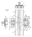
- Fig. 1 is a detail of the invention mullion-transom facade shown.
- the invention is shown here in view, the view is directed from outside to inside.
- Above and on the left are each in a vertical one Partial sectional view of the arrangement of the fastening profile 2 on the post 1 with screws 3 (for the post 1) and on the left, the arrangement of the fastening profile 2a with the aid of Screws 3a are shown on the latch 1a.
- Fig. 1 is a variant of the invention on the right side Solution shown.
- the post 1 facing the end 13 a recess 9.
- Die Recess 9 is designed so that this only on the Outside (as shown here) is open in the inside directed inside but the node is completely in Wood executed to the consistent appearance of the wooden facade not to interfere. In this respect, the recess 9 pocket-like.
- This first Part 4 is designed for example as an aluminum profile and can be cut to length according to the desired dimensions.
- this first part 4 is essentially U-shaped, with the two legs 4a of the U an end-side projection 4b or edge, whereby the first part 4 at the leg end wider is like in the foot area.
- This first part 4 cooperates with a second part 5, which with fastening screws 6a in the pocket-like Recess 9 is fixed to the front side of the bolt 1a.
- the second part 5 is substantially U-shaped, exactly taken C-shaped, such that the two above Leg 5a at their ends an inner curvature, in a C-profile typical.
- the dimensions of the first part 4 and the second part. 5 are dimensioned so that the outer dimension of the legs 4a and the supernatants 4b of the first part 4 a fit in the inner dimension of the legs 5a of the C-shaped second part. 5 results, that is, the supernatants 4b lie with their end faces on the inner sides of the legs 5a and the supernatants 5b on the outsides of the legs 4a. This will achieve that the two parts 4 and 5 along its longitudinal axis are nestable. Will be the first one Part 4 with one or more screws 6 on the post 1 fixed, it creates a torsion or torsion resistant Connection, if the second part 5 attached thereto is.
- both the first and the second parts 4, 5 formed as an aluminum part. It gets through, for example gained an extrusion process. But it is also possible corresponding iron parts, forgings or bent sheet metal parts and so on here.
- the assembly of the bolt 1a is carried out by attaching the Bolt 1a from the inside out.
- the Bar 1a has in its recess 9, the second part. 5
- the Recess 9 is oriented to the outside.
- Backside from the outside are the nested parts 4 and 5 accessible and now there is a screwing of the two parts 4 and 5 such that a clamping screw 8 is screwed into the channel 14 becomes.
- the channel 14 is limited on the one hand by the Inner wall of the outer C-profile and here in particular the supernatant 5b on the outer leg 5a of the C's inward points and the outer edge of the flange-like projection 4b of the Leg 4a of the U-shaped first part 4, which in the C-shaped Part 5 is inserted.
- the clamping screw 8 is according to the invention, for example a conventional screw, but it has the hereby Task to stretch the two parts 4 and 5 apart, since the dimension of the screw in relation to the channel dimensions are designed so that a longitudinal movement of the bolt profile 1a takes place on the post 1, whereby the latch 1a the post 1 is pressed.
- this invention not only achieves a torsion resistant Connecting or stiffening the latch profile 1a on Post 1, but at the same time a gap-free assembly, as desired, the bolt 1a on the post 1.
- the arrangement is chosen so that two channels 14 at the respective legs 4a, 5a of the part 4 and 5, respectively result.
- the fastening profile 2a which horizontally oriented is threaded, also bolted to the stiffener.
- the second part 5 channel-like openings 8a provided, in which corresponding fastening screws 7 for attaching the fastening profile 2a are screwed.
- the Openings 8a are channel-like and at a Extrusion process for the production of the second part 5 easily to incorporate.
- the arrangement of the openings 8a is in particular advantageous as the load on the mounting profile 2a, introduced directly into the stiffening and in the second part 5, the first part 4, directly in the post 1 is transferred.
- FIG. 1 A further variant of the invention is shown in FIG which the fastening profile 2, which runs vertically, a recess 9 has, in which a profile projection 10 of the horizontally extending fastening profiles 2a stands.
- This profile projection 10 is provided with a screw 11 in the Post 2 screwed. Again, there is a load dissipation of the profile 2a directly into the post 1.
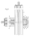
- Fig. 3 the principle of kinematic reversal is particular shown in the arrangement of parts 4 and 5.
- the C-shaped, larger part 5 is not in this variant on the bolt 1a, but on the post 1 with appropriate mounting screws 6a attached.
- the small first part 4 is in the recess 9 attached to the front of the latch 1a.
- the channels 14, in which the clamping screws. 8 are rotatable. In this case then lie the openings 8a with respect to the bar profile not inside but outside.
- Another advantage of the invention is that in the workshop-side preparation of the facade assembly of the both parts 4 and 5 is prepared, which achieves that the relative positioning of bar 1a and post 1 is set equal workshop. This is simply the Length of parts 4 and 5 selected according to the depth of the bolt. This ensures that the latch 1a with respect pinned in the right place, so a smooth, internal surface of wood results, which is gap-free.
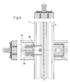
- the part 4 and the part 5 are carried out in this way, that a Verpress Anlagenkeit such that no Gap formed between post 1 and latch 1a. This will by appropriate pre and residues on the parts 4 and 5 generally achieved, but it is also possible to appropriate Wedge constructions to be chosen with inclined planes at the Share 4, 5 interact and so compressing the Bolt and the post at the junction result.
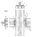
- Fig. 5 is a stiffener for a mullion and transom construction presented in a more compact design.
- the depth of the Parts 4, 5 is compared to the embodiment of FIGS. 1 to 4 much lower, the arrangement is in this case, however identical to the previously described embodiments.
- the two U-shaped parts 4, 5, at the legs at right angles formed projections 4 a, 5 a are formed form, as well previously described, the channel 14, in the one for bracing
- Both parts provided clamping element 15 can be inserted. at this clamping element 15 are screws, pins, Wedges and the like, which will be described later.
- the two parts 4, 5 interchangeable, so that part 4 in the recess in the bolt and part 5 are to be fastened to the outside of the post 1. Due to this compact design, the edge of the recess is relatively low, that is, he can have a greater power pick up and the risk of chipping is at this point of the bolt substantially reduced.
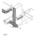
- FIGS. 6 to 8 show three variants of a connection between post 1 and latch 1a shown.
- Fig. 6 is the first part 4 receiving second part 5 on the side wall a post 1 attached. By means of screws 6 takes place the attachment.
- a stop 29 on part 4 prevents that the latch 1a pushed out too far over part 5 is, so that its position relative to the post 1 aligned is.
- This stop 29 consists of one, advantageously molded or punched from a sheet metal component with a screw 6b on the latch 1a can be fastened.
- This stop 29 is also like the first part 4 in the recess 9 of Riegels 1a sunk. After nesting of both parts 4, 5 together, the front edge of the recess 9 of the Riegelels 1a flush to the side wall of the post 1 at. through the clamping elements 15 are both parts 4, 5 with each other braced.
- the attachment profile 2a is by means of additional Screws (not shown) attached to the latch 1a. At this fastening element can now be attached to the facade element with the stiffener acting on them Torque in the post 1 derived.
- the fastening profile 2a is also by means of Clamping elements 15 on the stiffener and by another Screws (not shown) attached to the latch 1a.
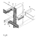
- Fig. 8 an embodiment of the invention is shown in the combination of a stiffening means of the parts 4, 5 and a stiffening means of a profile projection 10 shown is.
- the clamping elements 15 are used for attachment the fastening profile 2a with the stiffener, wherein
- the profile projection 10 in a recess 12 in Mounting profile 2a of the post 1 engages. In this way the load is over the first (through the parts 4, 5) and over the second reinforcement (profile projection 10 in recess 12) derived on the post 1.
- This variant according to the invention as described and shown in Fig. 8, achieved that even higher loads on facade elements in the inventive Post-and-beam facades are absorbed and diverted can.
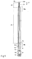
- Fig. 9 is a side view and a bottom view consisting from the parts 4, 5, shown.
- the one by the supernatants and leg-shaped channel 14 points in the region of Channel 18b has a narrowing 16.
- This narrowing 16 will by a deformation 19 of the supernatant 4b of the male first part 4 formed. This deformation 19 extends only over a partial region of the supernatant 4b.
- FIG. 9 shows an embodiment of the invention, in which only one deformation 19 on the supernatant 4b is provided.
- the 19 caused by this deformation constriction 16 of the channel 14 is in the region of the channel end 18b.
- the clamping element 15 is inserted.
- This Clamping element 15 consists of a smooth pin portion 21 and a thread 23 having area 22.
- the thread 23rd cuts into the material of the channel boundary.
- the Length of the pin is chosen such that first the thread 23rd engages the channel boundary before the tip 24a of the pin-shaped portion 21 enters the region of the constriction 16. By further screwing the pin comes the pointed tapered tip 24a of the pin in the constriction 16 and clamped the two parts 4, 5 with each other.
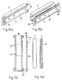
- FIGS. 10a to 10d the further embodiment of a Clamping element 15 for clamping the parts 4, 5 with each other shown.
- This clamping element consists of a bracket 25, consisting of two mutually substantially parallel Pins 26 consists. Both pins are at one end with each other connected.
- the bracket 25 is made bent a wire.
- the bracket 25 is with its pins 26 in the channels 14 of the stiffener insertable.
- the straight pins 16 act the bracket 25 with the constriction 16 bracing together, so that a longitudinal movement of the two parts 4, 5 avoided each other becomes.
- the Pins 26, a bend 27 which is connected to the constriction 16 of the Channel 14 interact and so the two parts 4, 5 against each other fix.
- Fig. 10b an embodiment is shown, in which see how the bend 27 with the constriction 16 in the channel 14th interacts.
- the bend 27 and constriction 16 toward each other come lie, sets the clamping action of the clamping element 15th one.
- the bracket 25 in the area in which the two pins 26 are interconnected to make wider than the clear width between the legs 5a of the part 5, so that the Bracket 25 does not slip too far in part 5.
- the pins 26 on bent ends 28, which slip of the bracket 25 in the other direction also prevent.
- the fact that the two pins 26 against each other are elastic, the bracket 25 can be easily used in Part 5 become.
- an embodiment of a stiffener is shown, at the part 4 to be picked up by the second part 5 consists of two sub-elements 30. These two sub-elements 30th are also in cross section, as the originally shown Part 4, T-shaped, wherein the crossbar of the T's of part 5 is added. Again, between the Transverse web of the T and the supernatants 5 b formed a channel, the is widened with the clamping screws. Two or more such sub-elements 30 can be used to form the stiffening on Post 1 may be provided. Again, it is possible both To interchange parts with each other, so that the elements 30 am Bar 1a and part 5 is fixed to the post 1. At a not shown version of the part 4 receiving part 5, part 5 may also be formed multi-element, so that the parts are associated with the parts 30. On This way is an even easier and easier way formed to form a stiffener.
Applications Claiming Priority (2)
| Application Number | Priority Date | Filing Date | Title |
|---|---|---|---|
| DE20319976 | 2003-12-23 | ||
| DE20319976U | 2003-12-23 |
Publications (3)
| Publication Number | Publication Date |
|---|---|
| EP1548200A2 true EP1548200A2 (fr) | 2005-06-29 |
| EP1548200A3 EP1548200A3 (fr) | 2006-09-20 |
| EP1548200B1 EP1548200B1 (fr) | 2011-04-20 |
Family
ID=34530447
Family Applications (1)
| Application Number | Title | Priority Date | Filing Date |
|---|---|---|---|
| EP04030614A Active EP1548200B1 (fr) | 2003-12-23 | 2004-12-23 | Façade avec montants et traverses |
Country Status (4)
| Country | Link |
|---|---|
| EP (1) | EP1548200B1 (fr) |
| AT (1) | ATE506498T1 (fr) |
| DE (2) | DE502004012413D1 (fr) |
| DK (1) | DK1548200T3 (fr) |
Cited By (4)
| Publication number | Priority date | Publication date | Assignee | Title |
|---|---|---|---|---|
| DE202012101289U1 (de) * | 2012-04-11 | 2013-07-12 | SCHÜCO International KG | T-Verbindung und Pfosten-Riegel-Konstruktion |
| DE202015104250U1 (de) | 2015-08-12 | 2016-11-16 | Raico Bautechnik Gmbh | Pfosten-Riegel-Verbindung |
| CN107762021A (zh) * | 2017-10-27 | 2018-03-06 | 湖南省金为新材料科技有限公司 | 后装横龙骨的幕墙龙骨连接结构 |
| CN108130966A (zh) * | 2018-02-28 | 2018-06-08 | 青岛宏海幕墙有限公司 | 一种玻璃幕墙横竖料连接结构 |
Citations (1)
| Publication number | Priority date | Publication date | Assignee | Title |
|---|---|---|---|---|
| DE19506580A1 (de) | 1995-02-24 | 1996-09-05 | Inst Fenstertechnik Ev | Anschlußverbindung zur Verbindung zweier Tragelemente, insbesondere Pfosten-Riegel-Verbindung für den Fassadenbau |
Family Cites Families (2)
| Publication number | Priority date | Publication date | Assignee | Title |
|---|---|---|---|---|
| DE19849152C5 (de) * | 1998-10-26 | 2013-10-10 | Gutmann Ag | Pfosten-Riegelverbindung |
| DE10110799A1 (de) * | 2001-03-06 | 2002-09-12 | Raico Bautechnik Gmbh | Verbindung für zwei Bauelemente |
-
2004
- 2004-12-23 EP EP04030614A patent/EP1548200B1/fr active Active
- 2004-12-23 DK DK04030614.4T patent/DK1548200T3/da active
- 2004-12-23 DE DE502004012413T patent/DE502004012413D1/de active Active
- 2004-12-23 AT AT04030614T patent/ATE506498T1/de active
- 2004-12-23 DE DE202004020148U patent/DE202004020148U1/de not_active Expired - Lifetime
Patent Citations (1)
| Publication number | Priority date | Publication date | Assignee | Title |
|---|---|---|---|---|
| DE19506580A1 (de) | 1995-02-24 | 1996-09-05 | Inst Fenstertechnik Ev | Anschlußverbindung zur Verbindung zweier Tragelemente, insbesondere Pfosten-Riegel-Verbindung für den Fassadenbau |
Cited By (5)
| Publication number | Priority date | Publication date | Assignee | Title |
|---|---|---|---|---|
| DE202012101289U1 (de) * | 2012-04-11 | 2013-07-12 | SCHÜCO International KG | T-Verbindung und Pfosten-Riegel-Konstruktion |
| DE202015104250U1 (de) | 2015-08-12 | 2016-11-16 | Raico Bautechnik Gmbh | Pfosten-Riegel-Verbindung |
| EP3130717A1 (fr) | 2015-08-12 | 2017-02-15 | Raico Bautechnik GmbH | Liaison poteau/verrou |
| CN107762021A (zh) * | 2017-10-27 | 2018-03-06 | 湖南省金为新材料科技有限公司 | 后装横龙骨的幕墙龙骨连接结构 |
| CN108130966A (zh) * | 2018-02-28 | 2018-06-08 | 青岛宏海幕墙有限公司 | 一种玻璃幕墙横竖料连接结构 |
Also Published As
| Publication number | Publication date |
|---|---|
| EP1548200A3 (fr) | 2006-09-20 |
| EP1548200B1 (fr) | 2011-04-20 |
| DK1548200T3 (da) | 2011-08-01 |
| ATE506498T1 (de) | 2011-05-15 |
| DE202004020148U1 (de) | 2005-05-12 |
| DE502004012413D1 (de) | 2011-06-01 |
Similar Documents
| Publication | Publication Date | Title |
|---|---|---|
| EP0784126B1 (fr) | Construction d'ossature faite de barres profilées | |
| DE1484078A1 (de) | Trennwand | |
| EP2685111A1 (fr) | Dispositif de serrage de connexion amovibles de deux pièces profilées | |
| DE202006003836U1 (de) | Deckenschalungssystem | |
| DE102013100189A1 (de) | T-Verbindung und Pfosten-Riegel-Konstruktion | |
| EP1754841B1 (fr) | Profilé isolant | |
| EP1915539B1 (fr) | Dispositif de raccordement basculant | |
| EP2055888A2 (fr) | Porte dotée d'un joint et joint de porte correspondant | |
| DE10016012B4 (de) | Verbundprofil für Fenster, Fassaden, Türen oder Lichtdächer | |
| EP0976891B1 (fr) | Système de construction | |
| DE4322253A1 (de) | Schalung mit Schaltafeln und Verbindungsmitteln | |
| DE2812128A1 (de) | Waermeisolierender profilkoerper | |
| EP1548200A2 (fr) | Façade avec montants et traverses | |
| EP3293336B1 (fr) | Rail de retenue pour un balcon français ainsi que dispositif et système de retenue associés | |
| DE1429466B2 (de) | Moebel bei dem aneinandergrenzende bauteile mit einem ihnen gemeinsamen pfosten verbunden sind | |
| EP1126099A2 (fr) | Dispositif de fixation pour éléments de façade en plaques | |
| DE202011108692U1 (de) | Hohlprofil und Hallengerüst mit einem solchen Profil | |
| DE202007007976U1 (de) | Montagesystem insbesondere Solarmodule | |
| DE8230619U1 (de) | Traegerprofil | |
| EP0004666B1 (fr) | Profilé composite | |
| DE202017102916U1 (de) | Profilelement zur lastübertragenden Verbindung mit einer Abschattungseinrichtung und mit einem integrierten Zugelement | |
| DE3128505A1 (de) | Vorrichtung zur knotenverbindung hoelzerner fachwerksstaebe | |
| EP2378045A2 (fr) | Disque en verre isolant | |
| DE202004008863U1 (de) | Profilverbindungssystem | |
| DE102005056129B4 (de) | Eckverbindungsanordnung mit Verzahnung |
Legal Events
| Date | Code | Title | Description |
|---|---|---|---|
| PUAI | Public reference made under article 153(3) epc to a published international application that has entered the european phase |
Free format text: ORIGINAL CODE: 0009012 |
|
| AK | Designated contracting states |
Kind code of ref document: A2 Designated state(s): AT BE BG CH CY CZ DE DK EE ES FI FR GB GR HU IE IS IT LI LT LU MC NL PL PT RO SE SI SK TR |
|
| AX | Request for extension of the european patent |
Extension state: AL BA HR LV MK YU |
|
| PUAL | Search report despatched |
Free format text: ORIGINAL CODE: 0009013 |
|
| AK | Designated contracting states |
Kind code of ref document: A3 Designated state(s): AT BE BG CH CY CZ DE DK EE ES FI FR GB GR HU IE IS IT LI LT LU MC NL PL PT RO SE SI SK TR |
|
| AX | Request for extension of the european patent |
Extension state: AL BA HR LV MK YU |
|
| 17P | Request for examination filed |
Effective date: 20061223 |
|
| 17Q | First examination report despatched |
Effective date: 20070329 |
|
| AKX | Designation fees paid |
Designated state(s): AT BE BG CH CY CZ DE DK EE ES FI FR GB GR HU IE IS IT LI LT LU MC NL PL PT RO SE SI SK TR |
|
| AXX | Extension fees paid |
Extension state: LV Payment date: 20061223 Extension state: MK Payment date: 20061223 Extension state: AL Payment date: 20061223 Extension state: HR Payment date: 20061223 Extension state: YU Payment date: 20061223 Extension state: BA Payment date: 20061223 |
|
| GRAP | Despatch of communication of intention to grant a patent |
Free format text: ORIGINAL CODE: EPIDOSNIGR1 |
|
| GRAS | Grant fee paid |
Free format text: ORIGINAL CODE: EPIDOSNIGR3 |
|
| GRAA | (expected) grant |
Free format text: ORIGINAL CODE: 0009210 |
|
| AK | Designated contracting states |
Kind code of ref document: B1 Designated state(s): AT BE BG CH CY CZ DE DK EE ES FI FR GB GR HU IE IS IT LI LT LU MC NL PL PT RO SE SI SK TR |
|
| AX | Request for extension of the european patent |
Extension state: AL BA HR LV MK YU |
|
| REG | Reference to a national code |
Ref country code: GB Ref legal event code: FG4D Free format text: NOT ENGLISH |
|
| REG | Reference to a national code |
Ref country code: CH Ref legal event code: NV Representative=s name: LUCHS & PARTNER AG PATENTANWAELTE Ref country code: CH Ref legal event code: EP |
|
| REG | Reference to a national code |
Ref country code: IE Ref legal event code: FG4D Free format text: LANGUAGE OF EP DOCUMENT: GERMAN |
|
| REF | Corresponds to: |
Ref document number: 502004012413 Country of ref document: DE Date of ref document: 20110601 Kind code of ref document: P |
|
| REG | Reference to a national code |
Ref country code: DE Ref legal event code: R096 Ref document number: 502004012413 Country of ref document: DE Effective date: 20110601 |
|
| REG | Reference to a national code |
Ref country code: NL Ref legal event code: T3 |
|
| REG | Reference to a national code |
Ref country code: DK Ref legal event code: T3 |
|
| LTIE | Lt: invalidation of european patent or patent extension |
Effective date: 20110420 |
|
| PG25 | Lapsed in a contracting state [announced via postgrant information from national office to epo] |
Ref country code: SE Free format text: LAPSE BECAUSE OF FAILURE TO SUBMIT A TRANSLATION OF THE DESCRIPTION OR TO PAY THE FEE WITHIN THE PRESCRIBED TIME-LIMIT Effective date: 20110420 Ref country code: PT Free format text: LAPSE BECAUSE OF FAILURE TO SUBMIT A TRANSLATION OF THE DESCRIPTION OR TO PAY THE FEE WITHIN THE PRESCRIBED TIME-LIMIT Effective date: 20110822 Ref country code: LT Free format text: LAPSE BECAUSE OF FAILURE TO SUBMIT A TRANSLATION OF THE DESCRIPTION OR TO PAY THE FEE WITHIN THE PRESCRIBED TIME-LIMIT Effective date: 20110420 |
|
| REG | Reference to a national code |
Ref country code: IE Ref legal event code: FD4D |
|
| PG25 | Lapsed in a contracting state [announced via postgrant information from national office to epo] |
Ref country code: GR Free format text: LAPSE BECAUSE OF FAILURE TO SUBMIT A TRANSLATION OF THE DESCRIPTION OR TO PAY THE FEE WITHIN THE PRESCRIBED TIME-LIMIT Effective date: 20110721 Ref country code: SI Free format text: LAPSE BECAUSE OF FAILURE TO SUBMIT A TRANSLATION OF THE DESCRIPTION OR TO PAY THE FEE WITHIN THE PRESCRIBED TIME-LIMIT Effective date: 20110420 Ref country code: FI Free format text: LAPSE BECAUSE OF FAILURE TO SUBMIT A TRANSLATION OF THE DESCRIPTION OR TO PAY THE FEE WITHIN THE PRESCRIBED TIME-LIMIT Effective date: 20110420 Ref country code: IS Free format text: LAPSE BECAUSE OF FAILURE TO SUBMIT A TRANSLATION OF THE DESCRIPTION OR TO PAY THE FEE WITHIN THE PRESCRIBED TIME-LIMIT Effective date: 20110820 Ref country code: ES Free format text: LAPSE BECAUSE OF FAILURE TO SUBMIT A TRANSLATION OF THE DESCRIPTION OR TO PAY THE FEE WITHIN THE PRESCRIBED TIME-LIMIT Effective date: 20110731 Ref country code: CY Free format text: LAPSE BECAUSE OF FAILURE TO SUBMIT A TRANSLATION OF THE DESCRIPTION OR TO PAY THE FEE WITHIN THE PRESCRIBED TIME-LIMIT Effective date: 20110420 |
|
| PG25 | Lapsed in a contracting state [announced via postgrant information from national office to epo] |
Ref country code: CZ Free format text: LAPSE BECAUSE OF FAILURE TO SUBMIT A TRANSLATION OF THE DESCRIPTION OR TO PAY THE FEE WITHIN THE PRESCRIBED TIME-LIMIT Effective date: 20110420 Ref country code: IE Free format text: LAPSE BECAUSE OF FAILURE TO SUBMIT A TRANSLATION OF THE DESCRIPTION OR TO PAY THE FEE WITHIN THE PRESCRIBED TIME-LIMIT Effective date: 20110420 Ref country code: EE Free format text: LAPSE BECAUSE OF FAILURE TO SUBMIT A TRANSLATION OF THE DESCRIPTION OR TO PAY THE FEE WITHIN THE PRESCRIBED TIME-LIMIT Effective date: 20110420 |
|
| PLBE | No opposition filed within time limit |
Free format text: ORIGINAL CODE: 0009261 |
|
| STAA | Information on the status of an ep patent application or granted ep patent |
Free format text: STATUS: NO OPPOSITION FILED WITHIN TIME LIMIT |
|
| PG25 | Lapsed in a contracting state [announced via postgrant information from national office to epo] |
Ref country code: RO Free format text: LAPSE BECAUSE OF FAILURE TO SUBMIT A TRANSLATION OF THE DESCRIPTION OR TO PAY THE FEE WITHIN THE PRESCRIBED TIME-LIMIT Effective date: 20110420 Ref country code: SK Free format text: LAPSE BECAUSE OF FAILURE TO SUBMIT A TRANSLATION OF THE DESCRIPTION OR TO PAY THE FEE WITHIN THE PRESCRIBED TIME-LIMIT Effective date: 20110420 Ref country code: PL Free format text: LAPSE BECAUSE OF FAILURE TO SUBMIT A TRANSLATION OF THE DESCRIPTION OR TO PAY THE FEE WITHIN THE PRESCRIBED TIME-LIMIT Effective date: 20110420 |
|
| 26N | No opposition filed |
Effective date: 20120123 |
|
| REG | Reference to a national code |
Ref country code: DE Ref legal event code: R097 Ref document number: 502004012413 Country of ref document: DE Effective date: 20120123 |
|
| PG25 | Lapsed in a contracting state [announced via postgrant information from national office to epo] |
Ref country code: MC Free format text: LAPSE BECAUSE OF NON-PAYMENT OF DUE FEES Effective date: 20111231 |
|
| PG25 | Lapsed in a contracting state [announced via postgrant information from national office to epo] |
Ref country code: BG Free format text: LAPSE BECAUSE OF FAILURE TO SUBMIT A TRANSLATION OF THE DESCRIPTION OR TO PAY THE FEE WITHIN THE PRESCRIBED TIME-LIMIT Effective date: 20110720 |
|
| PG25 | Lapsed in a contracting state [announced via postgrant information from national office to epo] |
Ref country code: TR Free format text: LAPSE BECAUSE OF FAILURE TO SUBMIT A TRANSLATION OF THE DESCRIPTION OR TO PAY THE FEE WITHIN THE PRESCRIBED TIME-LIMIT Effective date: 20110420 |
|
| PG25 | Lapsed in a contracting state [announced via postgrant information from national office to epo] |
Ref country code: HU Free format text: LAPSE BECAUSE OF FAILURE TO SUBMIT A TRANSLATION OF THE DESCRIPTION OR TO PAY THE FEE WITHIN THE PRESCRIBED TIME-LIMIT Effective date: 20110420 |
|
| PGFP | Annual fee paid to national office [announced via postgrant information from national office to epo] |
Ref country code: LU Payment date: 20131219 Year of fee payment: 10 |
|
| PGFP | Annual fee paid to national office [announced via postgrant information from national office to epo] |
Ref country code: DK Payment date: 20140106 Year of fee payment: 10 |
|
| REG | Reference to a national code |
Ref country code: DK Ref legal event code: EBP Effective date: 20141231 |
|
| PG25 | Lapsed in a contracting state [announced via postgrant information from national office to epo] |
Ref country code: LU Free format text: LAPSE BECAUSE OF NON-PAYMENT OF DUE FEES Effective date: 20141223 |
|
| REG | Reference to a national code |
Ref country code: FR Ref legal event code: PLFP Year of fee payment: 12 |
|
| PG25 | Lapsed in a contracting state [announced via postgrant information from national office to epo] |
Ref country code: DK Free format text: LAPSE BECAUSE OF NON-PAYMENT OF DUE FEES Effective date: 20141231 |
|
| REG | Reference to a national code |
Ref country code: FR Ref legal event code: PLFP Year of fee payment: 13 |
|
| REG | Reference to a national code |
Ref country code: FR Ref legal event code: PLFP Year of fee payment: 14 |
|
| PGFP | Annual fee paid to national office [announced via postgrant information from national office to epo] |
Ref country code: GB Payment date: 20201222 Year of fee payment: 17 |
|
| PGFP | Annual fee paid to national office [announced via postgrant information from national office to epo] |
Ref country code: BE Payment date: 20201217 Year of fee payment: 17 |
|
| PGFP | Annual fee paid to national office [announced via postgrant information from national office to epo] |
Ref country code: NL Payment date: 20201217 Year of fee payment: 17 |
|
| PGFP | Annual fee paid to national office [announced via postgrant information from national office to epo] |
Ref country code: IT Payment date: 20201230 Year of fee payment: 17 |
|
| REG | Reference to a national code |
Ref country code: NL Ref legal event code: MM Effective date: 20220101 |
|
| GBPC | Gb: european patent ceased through non-payment of renewal fee |
Effective date: 20211223 |
|
| REG | Reference to a national code |
Ref country code: BE Ref legal event code: MM Effective date: 20211231 |
|
| PG25 | Lapsed in a contracting state [announced via postgrant information from national office to epo] |
Ref country code: NL Free format text: LAPSE BECAUSE OF NON-PAYMENT OF DUE FEES Effective date: 20220101 |
|
| PG25 | Lapsed in a contracting state [announced via postgrant information from national office to epo] |
Ref country code: GB Free format text: LAPSE BECAUSE OF NON-PAYMENT OF DUE FEES Effective date: 20211223 |
|
| PG25 | Lapsed in a contracting state [announced via postgrant information from national office to epo] |
Ref country code: BE Free format text: LAPSE BECAUSE OF NON-PAYMENT OF DUE FEES Effective date: 20211231 |
|
| PG25 | Lapsed in a contracting state [announced via postgrant information from national office to epo] |
Ref country code: IT Free format text: LAPSE BECAUSE OF NON-PAYMENT OF DUE FEES Effective date: 20211223 |
|
| PGFP | Annual fee paid to national office [announced via postgrant information from national office to epo] |
Ref country code: CH Payment date: 20230103 Year of fee payment: 19 |
|
| PGFP | Annual fee paid to national office [announced via postgrant information from national office to epo] |
Ref country code: DE Payment date: 20230209 Year of fee payment: 19 |
|
| PGFP | Annual fee paid to national office [announced via postgrant information from national office to epo] |
Ref country code: FR Payment date: 20231219 Year of fee payment: 20 Ref country code: AT Payment date: 20231214 Year of fee payment: 20 |