EP1548200A2 - Mullion and transom facade - Google Patents
Mullion and transom facade Download PDFInfo
- Publication number
- EP1548200A2 EP1548200A2 EP04030614A EP04030614A EP1548200A2 EP 1548200 A2 EP1548200 A2 EP 1548200A2 EP 04030614 A EP04030614 A EP 04030614A EP 04030614 A EP04030614 A EP 04030614A EP 1548200 A2 EP1548200 A2 EP 1548200A2
- Authority
- EP
- European Patent Office
- Prior art keywords
- post
- parts
- channel
- profile
- clamping element
- Prior art date
- Legal status (The legal status is an assumption and is not a legal conclusion. Google has not performed a legal analysis and makes no representation as to the accuracy of the status listed.)
- Granted
Links
- 230000002787 reinforcement Effects 0.000 claims abstract description 5
- 239000011521 glass Substances 0.000 claims abstract description 3
- 239000003351 stiffener Substances 0.000 claims description 33
- 239000006228 supernatant Substances 0.000 claims description 29
- 230000000694 effects Effects 0.000 claims description 11
- 229910052751 metal Inorganic materials 0.000 claims description 10
- 239000002184 metal Substances 0.000 claims description 10
- 239000002023 wood Substances 0.000 claims description 7
- 238000001125 extrusion Methods 0.000 claims description 6
- 238000003780 insertion Methods 0.000 claims description 6
- 230000037431 insertion Effects 0.000 claims description 6
- 239000004033 plastic Substances 0.000 claims description 6
- 229920003023 plastic Polymers 0.000 claims description 6
- 238000009434 installation Methods 0.000 claims description 4
- 239000000463 material Substances 0.000 claims description 4
- 229920002430 Fibre-reinforced plastic Polymers 0.000 claims description 2
- 239000011151 fibre-reinforced plastic Substances 0.000 claims description 2
- 210000003195 fascia Anatomy 0.000 abstract 2
- 238000009413 insulation Methods 0.000 abstract 1
- 210000002414 leg Anatomy 0.000 description 30
- 238000013461 design Methods 0.000 description 9
- 229910052782 aluminium Inorganic materials 0.000 description 7
- XAGFODPZIPBFFR-UHFFFAOYSA-N aluminium Chemical compound [Al] XAGFODPZIPBFFR-UHFFFAOYSA-N 0.000 description 7
- 238000010276 construction Methods 0.000 description 6
- 238000000034 method Methods 0.000 description 5
- 230000008569 process Effects 0.000 description 4
- XEEYBQQBJWHFJM-UHFFFAOYSA-N Iron Chemical compound [Fe] XEEYBQQBJWHFJM-UHFFFAOYSA-N 0.000 description 3
- 230000008901 benefit Effects 0.000 description 3
- 239000002131 composite material Substances 0.000 description 3
- 230000002349 favourable effect Effects 0.000 description 3
- 238000012549 training Methods 0.000 description 3
- 210000000689 upper leg Anatomy 0.000 description 3
- 230000007423 decrease Effects 0.000 description 2
- 230000001419 dependent effect Effects 0.000 description 2
- 238000009472 formulation Methods 0.000 description 2
- 238000004519 manufacturing process Methods 0.000 description 2
- 239000000203 mixture Substances 0.000 description 2
- CWYNVVGOOAEACU-UHFFFAOYSA-N Fe2+ Chemical compound [Fe+2] CWYNVVGOOAEACU-UHFFFAOYSA-N 0.000 description 1
- 229910000831 Steel Inorganic materials 0.000 description 1
- 229910000754 Wrought iron Inorganic materials 0.000 description 1
- 238000010521 absorption reaction Methods 0.000 description 1
- 230000009471 action Effects 0.000 description 1
- AZDRQVAHHNSJOQ-UHFFFAOYSA-N alumane Chemical group [AlH3] AZDRQVAHHNSJOQ-UHFFFAOYSA-N 0.000 description 1
- 238000005452 bending Methods 0.000 description 1
- 150000001875 compounds Chemical class 0.000 description 1
- 238000011161 development Methods 0.000 description 1
- 238000009826 distribution Methods 0.000 description 1
- 238000005242 forging Methods 0.000 description 1
- 230000001771 impaired effect Effects 0.000 description 1
- 230000006872 improvement Effects 0.000 description 1
- 230000003993 interaction Effects 0.000 description 1
- 229910052742 iron Inorganic materials 0.000 description 1
- JEIPFZHSYJVQDO-UHFFFAOYSA-N iron(III) oxide Inorganic materials O=[Fe]O[Fe]=O JEIPFZHSYJVQDO-UHFFFAOYSA-N 0.000 description 1
- 150000002739 metals Chemical class 0.000 description 1
- 238000002360 preparation method Methods 0.000 description 1
- 238000003825 pressing Methods 0.000 description 1
- 238000012545 processing Methods 0.000 description 1
- 238000010079 rubber tapping Methods 0.000 description 1
- 238000003892 spreading Methods 0.000 description 1
- 230000007480 spreading Effects 0.000 description 1
- 239000010959 steel Substances 0.000 description 1
- 239000010902 straw Substances 0.000 description 1
- 238000012546 transfer Methods 0.000 description 1
- 230000009466 transformation Effects 0.000 description 1
Images


Classifications
-
- E—FIXED CONSTRUCTIONS
- E04—BUILDING
- E04B—GENERAL BUILDING CONSTRUCTIONS; WALLS, e.g. PARTITIONS; ROOFS; FLOORS; CEILINGS; INSULATION OR OTHER PROTECTION OF BUILDINGS
- E04B2/00—Walls, e.g. partitions, for buildings; Wall construction with regard to insulation; Connections specially adapted to walls
- E04B2/88—Curtain walls
- E04B2/96—Curtain walls comprising panels attached to the structure through mullions or transoms
- E04B2/965—Connections of mullions and transoms
Definitions
- the invention relates to a mullion and transom façade accordingly the preamble of claim 1.
- mullion-transom facades is a substantially vertical or horizontally extending support profile provided. That the Façade elements bearing fastening profile is either pressed directly on the support profile or with appropriate Fasteners attached to this.
- the supporting profiles themselves consist of a metal, such as steel, aluminum or The like, however, for the facades and support profiles Used wood. Such facades are, for example, too referred to as wood aluminum facades.
- the invention has set itself the task of a mullion-transom façade, as described above, available too in which a stable and torsionally stiff Connection between the horizontal and vertical facade element consists.
- the invention is based on a Post and beam facade, as described above, and proposes before, that in the junction of posts and bars a bolt torsion-fixing, defining stiffening is provided.
- the proposal according to the invention is a stiffening on Node between pole and latch.
- the node is doing through those areas on the post or bar defined, which in the finished facade in operative connection stand or touch each other.
- the arrangement is according to of the invention chosen so that the stiffener in the post or Bar is integrated and so the design of the facade is not impaired.
- the proposal according to the invention is the Node stiffened so that even at a considerable Load of the bolt this distortion remains.
- the invention proposes a total of three variants, such as this can be achieved.
- the first variant how will be described below, two interacting with each other Parts suggested.
- the Stiffening of a profile projection of the arranged on the bolt Fastening profiles achieved, this profile projection then attached to the post accordingly and / or if necessary directly above the post or on top of the post Post arranged profile is able to remove the load.
- the two aforementioned Suggestions combined, which is even more significant Increasing the stiffening results.
- the stiffener consists of two parts which can be joined together, with a first part at the side of the post and a second part is arranged on the front side of the bolt. Plugging means in this context, the insertion of the two parts into each other and their longitudinal mobility as a sliding movement. Between the first and the second part is a channel formed, which preferably over the entire length of the part extends.
- the attached to the front side of the bolt part is according to an embodiment of the invention on the bolt front side placed. According to a further embodiment of the invention However, it is intended to sink the part in a recess. In this way, the front side of the bolt is directly at the post, although between the posts and bars the Reinforcement is located.
- the two-piece Design of the stiffener has the advantage that this easy to assemble and, for example, already on the workshop side can be prepared, reducing the assembly effort the construction site is shortened considerably.
- the inventive Arrangement also allows that the horizontally extending Riegel can be retrofitted into the facade. By the invention, therefore, for example, a transformation of Post and beam façade easily possible. This works even with existing facades, with corresponding Elements equipped to be supplemented.
- the arrangement of a Channel between the two parts serves to appropriate To include clamping elements and the like. Since preferably the parts are made as profiled goods, extends Conveniently, the channel also equal over the entire length of the part.
- Both parts are fixed by bracing against each other.
- the Bracing is advantageously carried out by means of a tensioning element that can be used in the channel formed by the parts or is screwed.
- a tensioning element that can be used in the channel formed by the parts or is screwed.
- the parts to each other at least during the attachment of the Riegels at the post, have a fitting-in game.
- This installation play of course facilitates the assembly of the Tie at the post.
- the installation play allows a certain Alignment of the two elements to each other in order to optimize this align and also compensate for certain dimensional tolerances. is but then the bolt is placed in the desired position on the post, so by the use of the clamping element, as described, eliminated this installation play and the two parts tightly clamped together.
- the cooperating Parts of several channels, each for receiving a tensioning element exhibit. It is sufficient in the first variant of the invention already off, with a clamping element success of the invention to realize. But are the parts that work together formed several channels, so it is of course favorable by increasing the number of tensioning clamping elements to achieve an improvement in stability.
- the invention thus comprises both solutions in which only one Clamping element is used, as well as solutions in which a variety of clamping elements (two or more) used become.
- the part attached to the post almost extends over the entire post width. In this way, a large contact surface achieved, reducing the strength of the mullion-transom facade is increased.
- the part attached to the post extends however, according to an embodiment of the invention, almost only about entire post width so that it fits well in a recess insert and is not necessarily visible from the outside. Correspondingly long is the part attached to the bolt, so that both parts intermesh over their full length.
- this invention includes both solutions, depending on the in which proportions posts and bars installed to each other become.
- the clamping element acts on at least two Channel areas on the parts spanning a. Preferably lie these areas in the front and rear channel area. This can done by two short pins or screws, by both Ends of the channel are introduced into the channel. From The clamping force is introduced in front and from behind. The bracing However, it can also be done by means of a pen, the extends over the entire length of the channel and the Clamping force over the entire length of the parts extends. By distributing the clamping force over the entire length of the parts There is no game that can make you wobble. By the Distribution of the clamping areas on the front and rear Channel area is, without the bracing over the entire Length takes place, but evenly distributed.
- At least one of the parts is substantially U-shaped.
- This U-shaped part substantially decreases positively the second part in itself.
- This second part may consist of a profile part whose cross section at least the width of the U corresponds, so that both legs of the U include the profile part between them.
- the thigh The U's lie directly on two opposing Outside of the profile part.
- the Latch characterized in that the profile part is received by the "U" do not twist.
- the second Part of the stiffener also from a U-profile, with the Legs of this U-profile with their outsides on the insides abut the leg of the first part.
- the second Part C-shaped that is, the ends of the legs of the U have inwardly directed bends.
- This C-shaped part surrounds with the bends at least partly the first part. In this way is the contact surface enlarged between the first and second part, whereby the torsional strength is increased. So that from the Legs angled ends - so the bends - the can embrace the first part is either the first part with attached to the bolt a certain distance, or it is provided an undercut, which absorb the bends.
- a part that has undercuts can have a T-shaped cross-section.
- the T is with his vertical foot attached to the post or latch, while the C-shaped Part of the crossbeam of the T absorbs.
- the crossbeam is dimensioned such that it with its end faces on the insides of the legs of the U or the C's positive fit.
- the bearing surface should be as possible be chosen large, so that when applying a torque to the Latch, in the stiffening no play exists and so the Power is dissipated over the post.
- the parts are formed so that one part of the respective completely absorbs the other part. This means, if both parts are inserted into each other, none of the Parts over the other. This will be a very compact design for the stiffener formed, which is fine between posts and bars accommodate or slightly in a recess is recessed on the front side of the bolt can be.
- the bends at the ends of the legs of the U are in hereinafter referred to as supernatants.
- the first part is U-shaped with provided at the ends of the legs supernatants formed, but, according to a variant of the invention, the second part is also U-shaped with the Ends of the legs provided on supernatants.
- the overhangs of one of the parts can be aligned towards each other be.
- the substantially C-shaped Training one of the parts formed.
- the supernatants are aligned away from each other.
- This projection limits the parts edge-like. At the first Part is the edge to the outside and the second part inside directed.
- An essential feature of a variant according to the invention consists in that the end overhang of the first part opposite the end-side projection of the second part is aligned. In this way it is possible that the two Supernatants interact with each other. The two parts are bordered by the supernatants.
- the two parts By means of a sliding movement along its longitudinal axis the two parts are engaged with each other. A movement perpendicular to the longitudinal axis is thus locked out. Both parts are holding together. These Bracket is sufficient to lock the latch opposite the jamb Fasten.
- the two parts are designed in such a way that the outer dimension of the first part to fit in the inner dimension the leg of the second part sits. In this way results a torsion-free connection between posts and Bars.
- the contact surfaces are at spaced apart composite parts. To this Way, a channel or two channels is formed, which limits are from thighs and supernatants.
- Part multi-element execute.
- the individual elements of the Parts are located, for example, aligned on the post and / or on the bar.
- the aligned arrangement causes the individual elements together like a longitudinal, profile-like part to act.
- the design the individual elements for example, shorter ones Profile sections, it allows in a simple way the invention to adapt to the different post and bolt dimensions.
- the first and last element spaced as far as possible to order a To obtain as large as possible plant area and clamping range.
- the invention also makes it possible that, for example, on the Post the individual elements of the part are arranged or at the bar. Also, a combination of these two suggestions possible, for example, such that both the part of Post as well as the part of the bolt each multi-element is formed and these elements cooperate within the meaning of the invention.
- the C-shaped part Part formed like a button, so that the supernatants of the C's Head of the button absorbs.
- the neck of the button is located then between the supernatants of the C-shaped part.
- the clamping takes place by inserting a tensioning element, For example, screwing a screw in the channel, so that slipping of both parts now in their longitudinal orientation is prevented.
- a tensioning element For example, screwing a screw in the channel, so that slipping of both parts now in their longitudinal orientation is prevented.
- pins insert a wedge or other parts in the channel.
- the legs of both parts should not be different from each other be pressed away, otherwise the desired fit no longer is guaranteed. That is, the diameter of the screw is allowed be just as big as the distance between the legs of both parts from each other. The front sides of the supernatants remain on the legs of the other part fitting.
- a wedge or other clamping element in the channel causes at a loose connection of posts and bars to each other the two Parts are moved further into each other. To this It is achieved that the bolt pressed against the post is, creating a gap-free connection between posts and Bar is reached. After clamping the two parts together is a torsion-fixing attachment between Bar and posts reached.
- the cross section is over the entire length of the channel the same.
- the thread of a screw cuts into the material of the parts and fixes on this way both parts together.
- the invention is already threaded in the parts provided, in which the clamping screw are used can. In both cases, the channel is screwed through the clamping screw widened, so that the two parts together be tense. It can be with these clamping screws are short screws acting from either side or only be screwed into the canal from one side.
- two parts with a pin to brace each other wherein the diameter of the pin is slightly larger than that Diameter of the channel itself. Again, it is possible that It can, however, cause distortion by means of a pin also pins from both ends of the channel pressed into the channel become.
- the channel in one certain area to be provided with a constriction, so that the Diameter of the clamping element corresponds to the diameter of the channel and the tension effect occurs only in the area of the constriction.
- a clamping element has the differently shaped sections, is it is possible to set the clamping points targeted.
- the narrowing is provided in the end region of the channel, wherein the cross section of the clamping element is slightly larger than the Cross-section of the canal in the area of the narrowing, but smaller is the cross section of the channel in the remaining area.
- the clamping element over a portion or over the entire length of the channel and stretching on the parts acts. It is not mandatory that the Clamping element only over a certain, short area of the channel extends, according to the invention, it is possible that possible the entire length of the channel used by the clamping element is or the clamping element is also shorter.
- clamping element extends at least into the region of the narrowing in the channel.
- the constriction, the in the rear, the insertion opening of the clamping element on Channel is located remote end.
- the Clamping element for the second time in the context of the invention an expansion cause the two parts. So it's enough the length of the clamping element to be dimensioned so that this flat only this narrowing is achieved and it has a tightening effect. conveniently, but this narrowing is in the back of the canal, possibly at this rear end, provided.
- constriction is also possible.
- the area of the clamping element that is used in the State cooperates with the beginning region of the channel, formed with a thread that holds the two parts in this area clamped together.
- the constriction is advantageously produced by deforming the projections of the parts. In this way it is possible to narrow the constriction only in to provide a direction so that the height of the channel is smaller is as the width of the channel.
- the dimensions of the tension element one side and the arrangement the narrowing in the channel on the other hand is chosen so that the tip of the clamping element then prefers the constriction interacts when the thread is in the starting area of the channel intervenes. In this way, the clamping element so far in the Channel can be inserted until the thread engages and through Further rotation of the pin comes the tip of the clamping element in contact with the constriction, but can by the rotation easily be introduced into the narrowing.
- the clamping element consists of a pin, which is a smooth Pin area and a threaded area. Through the threaded area, it is possible, the clamping element in to fix and fix the channel. At the same time causes the thread also a nip of the parts.
- the smooth pin area in the area the tip of the pen is provided and the area with the Thread is disposed at the opposite end of the pin.
- the clamping element so illustrated is not like a Screw formed, as with a screw normally the Thread at the lower end, the screw head remote end, is arranged.
- the top of Clamping element is also used clamped.
- the dimensions of the clamping element on the one hand and the arrangement the constriction in the channel on the other hand is chosen so that the Tip of the clamping element preferably only then with the constriction cooperates when the thread in the beginning of the Channel already intervenes. So will be in two places at the same time of the channel, ie two channel areas, in the same way Spreading causes and so the two parts set to each other.
- a clamping element provided, consisting of two mutually parallel There is a pin connected by a bracket are.
- This clamping element is advantageously made made of a bent wire.
- the diameter of the pins is over their entire length the same, so that the clamping effect only in Area of narrowing in the channel acts.
- the pins on a bend the interact with the constrictions in the channel when the bracket is inserted. In this way, the clamping effect is increased, so that the compound is given a higher strength.
- a stop one of the parts provided which prevents the male Part all too far into the receiving part slips or slip out on the other side.
- a stopper is provided on one of the Parts molded or attached.
- This stop is advantageously provided on the male part, wherein the Width is greater than the height of the female part.
- This Stop consists of a T-shaped component, the is advantageously formed or punched out of a metal sheet is, wherein the crossbar of the T is longer than the distance the leg of the male part.
- the part connected to the latch is attached to the front of the bolt.
- Through a movement transverse to the longitudinal direction of the post are both parts stuck together.
- the insertion direction from front to back or from the back to the top is provided.
- the two parts of the stiffener transversely to the alignment of the post twisted on posts and bolts attached. With upright facade is thus the Latch inserted horizontally between two posts.
- the stiffener consisting of the two parts, find in a recess in the bolt recording.
- the recess pocket-like design In arrangement the stiffening perpendicular to the longitudinal direction of the post is advantageously the recess in the direction Facade outside open. From this side is the bar inserted between two posts. The recess may be in the direction Facade inside also be open. However, to the inward facing of the facade a continuous Appearance is advantageously the recess closed in this direction.
- the openings are advantageously channel-like, so they in the production of a profile from which the parts the stiffening consist, for example, in the extrusion process can be made.
- the parts of the stiffener are designed such that, for example the first part with the bolt and the second part with the post or the first part with the post and that second part are connected to the latch. Both parts are thus exchangeable.
- the parts of the stiffener are made of metal.
- Metals are iron, wrought iron or sheet metal. Prefers however, aluminum is provided as it is in processing in the Extrusion can be made, is easy and does not rust.
- the parts of the stiffener also made of plastic, in particular Fiber-reinforced plastic, are created, including composite materials can be used.
- the depth of the nested To make parts smaller than half Width of the post As a result, the recess on the front side of the post are not trained too deeply and it decreases the height of the edge boundary of the recess, the This has a higher stability, a higher counterforce can pick up and the risk of chipping the end wood strongly lowered.
- a Form profile overhang is provided for stiffening the arranged on the bolt mounting profile a Form profile overhang.
- This profile projection is with the Connected post.
- a fastening profile is arranged, it is possible to the profile supernatant to arrange between posts and fastening profile. So that the fastening profile of the post smooth on the post rests, can for the profile projection a recess in the Post be provided.
- the attachment profile of the post a recess on, in which the profile supernatant stands. In this way you have to no gaps are made on the post and the both mounting profiles, that of the post and that of the Riegel, just get up on the post.
- the attachment profile is by means of a fastener attached to the post.
- fasteners own Bolts, rivets and the like, but screws are preferred used, since these are easy to attach to the post, are solvable again and in relation to smooth parts like Bolt or nails make a tighter connection with the post.
- the fastening profile of the bolt is in the range of Profilschreibschreibes prefabricated with the post. Because the mounting profile as well as being in touch with the tie at the same time connected posts and bars. By Pressure on the outside of the mounting profile, for example from above, resulting from the arrangement of facade elements causes a torque on the mounting profile exercised and the profile supernatant communicating with the post stands, supported on the post. This way will also a stiffening of the mullion-transom construction in Node reached.
- the fastening profile with the clamping elements on the stiffener and in addition attached to the bolt with other fasteners is not limited.
- the support profile is designed as a wooden support profile.
- the invention is preferably used in wooden support profiles to here to achieve sufficient stiffening.
- Post-and-beam facades are used, in which the Example supporting profiles made of other materials, for example metal and so on.
- the support profile made of plastic consists, for example, straw-filled plastic profiles Can be used according to their outer sides are laminated.
- the invention is very variable in this regard used.
- there are also appropriate composite materials or equipped with Stahlarm réelle hollow profiles Plastic and so on can be used.
- the invention is also directed to a spit-like tensioning element, which for clamping two interlocking Parts is provided, wherein the clamping element is an element head below which there is a first connection area followed and followed by a pencil report.
- the cross section of the smooth pen area is smaller than the upper one first Connection area.
- the tensioning element runs pointed in the front, with which it is in one another connection region is introduced, whose cross-section is smaller than the cross section of the first connection area.
- the clamping element a thread on which it is the parts in the first connection area braced together.
- the pen area is which is below the first connection area located, equipped with a smooth outer surface. Just when the clamping element is helical and in the first connecting portion carries a thread is provided in that this pin area is opposite the first connection area stands back, so is designed narrower.
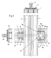
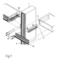
- Fig. 1 is a detail of the invention mullion-transom facade shown.
- the invention is shown here in view, the view is directed from outside to inside.
- Above and on the left are each in a vertical one Partial sectional view of the arrangement of the fastening profile 2 on the post 1 with screws 3 (for the post 1) and on the left, the arrangement of the fastening profile 2a with the aid of Screws 3a are shown on the latch 1a.
- Fig. 1 is a variant of the invention on the right side Solution shown.
- the post 1 facing the end 13 a recess 9.
- Die Recess 9 is designed so that this only on the Outside (as shown here) is open in the inside directed inside but the node is completely in Wood executed to the consistent appearance of the wooden facade not to interfere. In this respect, the recess 9 pocket-like.
- This first Part 4 is designed for example as an aluminum profile and can be cut to length according to the desired dimensions.
- this first part 4 is essentially U-shaped, with the two legs 4a of the U an end-side projection 4b or edge, whereby the first part 4 at the leg end wider is like in the foot area.
- This first part 4 cooperates with a second part 5, which with fastening screws 6a in the pocket-like Recess 9 is fixed to the front side of the bolt 1a.
- the second part 5 is substantially U-shaped, exactly taken C-shaped, such that the two above Leg 5a at their ends an inner curvature, in a C-profile typical.
- the dimensions of the first part 4 and the second part. 5 are dimensioned so that the outer dimension of the legs 4a and the supernatants 4b of the first part 4 a fit in the inner dimension of the legs 5a of the C-shaped second part. 5 results, that is, the supernatants 4b lie with their end faces on the inner sides of the legs 5a and the supernatants 5b on the outsides of the legs 4a. This will achieve that the two parts 4 and 5 along its longitudinal axis are nestable. Will be the first one Part 4 with one or more screws 6 on the post 1 fixed, it creates a torsion or torsion resistant Connection, if the second part 5 attached thereto is.
- both the first and the second parts 4, 5 formed as an aluminum part. It gets through, for example gained an extrusion process. But it is also possible corresponding iron parts, forgings or bent sheet metal parts and so on here.
- the assembly of the bolt 1a is carried out by attaching the Bolt 1a from the inside out.
- the Bar 1a has in its recess 9, the second part. 5
- the Recess 9 is oriented to the outside.
- Backside from the outside are the nested parts 4 and 5 accessible and now there is a screwing of the two parts 4 and 5 such that a clamping screw 8 is screwed into the channel 14 becomes.
- the channel 14 is limited on the one hand by the Inner wall of the outer C-profile and here in particular the supernatant 5b on the outer leg 5a of the C's inward points and the outer edge of the flange-like projection 4b of the Leg 4a of the U-shaped first part 4, which in the C-shaped Part 5 is inserted.
- the clamping screw 8 is according to the invention, for example a conventional screw, but it has the hereby Task to stretch the two parts 4 and 5 apart, since the dimension of the screw in relation to the channel dimensions are designed so that a longitudinal movement of the bolt profile 1a takes place on the post 1, whereby the latch 1a the post 1 is pressed.
- this invention not only achieves a torsion resistant Connecting or stiffening the latch profile 1a on Post 1, but at the same time a gap-free assembly, as desired, the bolt 1a on the post 1.
- the arrangement is chosen so that two channels 14 at the respective legs 4a, 5a of the part 4 and 5, respectively result.
- the fastening profile 2a which horizontally oriented is threaded, also bolted to the stiffener.
- the second part 5 channel-like openings 8a provided, in which corresponding fastening screws 7 for attaching the fastening profile 2a are screwed.
- the Openings 8a are channel-like and at a Extrusion process for the production of the second part 5 easily to incorporate.
- the arrangement of the openings 8a is in particular advantageous as the load on the mounting profile 2a, introduced directly into the stiffening and in the second part 5, the first part 4, directly in the post 1 is transferred.
- FIG. 1 A further variant of the invention is shown in FIG which the fastening profile 2, which runs vertically, a recess 9 has, in which a profile projection 10 of the horizontally extending fastening profiles 2a stands.
- This profile projection 10 is provided with a screw 11 in the Post 2 screwed. Again, there is a load dissipation of the profile 2a directly into the post 1.
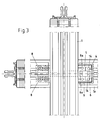
- Fig. 3 the principle of kinematic reversal is particular shown in the arrangement of parts 4 and 5.
- the C-shaped, larger part 5 is not in this variant on the bolt 1a, but on the post 1 with appropriate mounting screws 6a attached.
- the small first part 4 is in the recess 9 attached to the front of the latch 1a.
- the channels 14, in which the clamping screws. 8 are rotatable. In this case then lie the openings 8a with respect to the bar profile not inside but outside.
- Another advantage of the invention is that in the workshop-side preparation of the facade assembly of the both parts 4 and 5 is prepared, which achieves that the relative positioning of bar 1a and post 1 is set equal workshop. This is simply the Length of parts 4 and 5 selected according to the depth of the bolt. This ensures that the latch 1a with respect pinned in the right place, so a smooth, internal surface of wood results, which is gap-free.
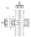
- the part 4 and the part 5 are carried out in this way, that a Verpress Anlagenkeit such that no Gap formed between post 1 and latch 1a. This will by appropriate pre and residues on the parts 4 and 5 generally achieved, but it is also possible to appropriate Wedge constructions to be chosen with inclined planes at the Share 4, 5 interact and so compressing the Bolt and the post at the junction result.
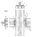
- Fig. 5 is a stiffener for a mullion and transom construction presented in a more compact design.
- the depth of the Parts 4, 5 is compared to the embodiment of FIGS. 1 to 4 much lower, the arrangement is in this case, however identical to the previously described embodiments.
- the two U-shaped parts 4, 5, at the legs at right angles formed projections 4 a, 5 a are formed form, as well previously described, the channel 14, in the one for bracing
- Both parts provided clamping element 15 can be inserted. at this clamping element 15 are screws, pins, Wedges and the like, which will be described later.
- the two parts 4, 5 interchangeable, so that part 4 in the recess in the bolt and part 5 are to be fastened to the outside of the post 1. Due to this compact design, the edge of the recess is relatively low, that is, he can have a greater power pick up and the risk of chipping is at this point of the bolt substantially reduced.
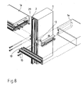
- FIGS. 6 to 8 show three variants of a connection between post 1 and latch 1a shown.
- Fig. 6 is the first part 4 receiving second part 5 on the side wall a post 1 attached. By means of screws 6 takes place the attachment.
- a stop 29 on part 4 prevents that the latch 1a pushed out too far over part 5 is, so that its position relative to the post 1 aligned is.
- This stop 29 consists of one, advantageously molded or punched from a sheet metal component with a screw 6b on the latch 1a can be fastened.
- This stop 29 is also like the first part 4 in the recess 9 of Riegels 1a sunk. After nesting of both parts 4, 5 together, the front edge of the recess 9 of the Riegelels 1a flush to the side wall of the post 1 at. through the clamping elements 15 are both parts 4, 5 with each other braced.
- the attachment profile 2a is by means of additional Screws (not shown) attached to the latch 1a. At this fastening element can now be attached to the facade element with the stiffener acting on them Torque in the post 1 derived.
- the fastening profile 2a is also by means of Clamping elements 15 on the stiffener and by another Screws (not shown) attached to the latch 1a.
- Fig. 8 an embodiment of the invention is shown in the combination of a stiffening means of the parts 4, 5 and a stiffening means of a profile projection 10 shown is.
- the clamping elements 15 are used for attachment the fastening profile 2a with the stiffener, wherein
- the profile projection 10 in a recess 12 in Mounting profile 2a of the post 1 engages. In this way the load is over the first (through the parts 4, 5) and over the second reinforcement (profile projection 10 in recess 12) derived on the post 1.
- This variant according to the invention as described and shown in Fig. 8, achieved that even higher loads on facade elements in the inventive Post-and-beam facades are absorbed and diverted can.
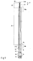
- Fig. 9 is a side view and a bottom view consisting from the parts 4, 5, shown.
- the one by the supernatants and leg-shaped channel 14 points in the region of Channel 18b has a narrowing 16.
- This narrowing 16 will by a deformation 19 of the supernatant 4b of the male first part 4 formed. This deformation 19 extends only over a partial region of the supernatant 4b.
- FIG. 9 shows an embodiment of the invention, in which only one deformation 19 on the supernatant 4b is provided.
- the 19 caused by this deformation constriction 16 of the channel 14 is in the region of the channel end 18b.
- the clamping element 15 is inserted.
- This Clamping element 15 consists of a smooth pin portion 21 and a thread 23 having area 22.
- the thread 23rd cuts into the material of the channel boundary.
- the Length of the pin is chosen such that first the thread 23rd engages the channel boundary before the tip 24a of the pin-shaped portion 21 enters the region of the constriction 16. By further screwing the pin comes the pointed tapered tip 24a of the pin in the constriction 16 and clamped the two parts 4, 5 with each other.
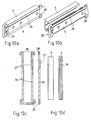
- FIGS. 10a to 10d the further embodiment of a Clamping element 15 for clamping the parts 4, 5 with each other shown.
- This clamping element consists of a bracket 25, consisting of two mutually substantially parallel Pins 26 consists. Both pins are at one end with each other connected.
- the bracket 25 is made bent a wire.
- the bracket 25 is with its pins 26 in the channels 14 of the stiffener insertable.
- the straight pins 16 act the bracket 25 with the constriction 16 bracing together, so that a longitudinal movement of the two parts 4, 5 avoided each other becomes.
- the Pins 26, a bend 27 which is connected to the constriction 16 of the Channel 14 interact and so the two parts 4, 5 against each other fix.
- Fig. 10b an embodiment is shown, in which see how the bend 27 with the constriction 16 in the channel 14th interacts.
- the bend 27 and constriction 16 toward each other come lie, sets the clamping action of the clamping element 15th one.
- the bracket 25 in the area in which the two pins 26 are interconnected to make wider than the clear width between the legs 5a of the part 5, so that the Bracket 25 does not slip too far in part 5.
- the pins 26 on bent ends 28, which slip of the bracket 25 in the other direction also prevent.
- the fact that the two pins 26 against each other are elastic, the bracket 25 can be easily used in Part 5 become.
- an embodiment of a stiffener is shown, at the part 4 to be picked up by the second part 5 consists of two sub-elements 30. These two sub-elements 30th are also in cross section, as the originally shown Part 4, T-shaped, wherein the crossbar of the T's of part 5 is added. Again, between the Transverse web of the T and the supernatants 5 b formed a channel, the is widened with the clamping screws. Two or more such sub-elements 30 can be used to form the stiffening on Post 1 may be provided. Again, it is possible both To interchange parts with each other, so that the elements 30 am Bar 1a and part 5 is fixed to the post 1. At a not shown version of the part 4 receiving part 5, part 5 may also be formed multi-element, so that the parts are associated with the parts 30. On This way is an even easier and easier way formed to form a stiffener.
Abstract
Description
Die Erfindung betrifft eine Pfosten-Riegel-Fassade entsprechend
dem Oberbegriff von Anspruch 1.The invention relates to a mullion and transom façade accordingly
the preamble of
Bei Pfosten-Riegel-Fassaden ist ein im Wesentlichen senkrecht oder waagerecht verlaufendes Tragprofil vorgesehen. Das die Fassadenelemente tragende Befestigungsprofil ist entweder direkt auf dem Tragprofil aufgepreßt oder mit entsprechenden Befestigungsmitteln an diesem befestigt. Die Tragprofile selbst bestehen aus einem Metall, wie Stahl, Aluminium oder dergleichen jedoch werden für die Fassaden auch Tragprofile aus Holz eingesetzt. Derartige Fassaden werden zum Beispiel auch als Holzaluminiumfassaden bezeichnet. In mullion-transom facades is a substantially vertical or horizontally extending support profile provided. That the Façade elements bearing fastening profile is either pressed directly on the support profile or with appropriate Fasteners attached to this. The supporting profiles themselves consist of a metal, such as steel, aluminum or The like, however, for the facades and support profiles Used wood. Such facades are, for example, too referred to as wood aluminum facades.
Auf den horizontal verlaufenden Befestigungsprofilen werden teilweise große Scheiben mit erheblichem Gewicht abgestellt.Be on the horizontally extending fastening profiles partially turned off large windows with considerable weight.
Durch die außermittige Belastung wirken entsprechende Kräfte auf das Riegelprofil. Es kommt zum Abkippen der Riegelkonstruktion aufgrund der Belastung.Due to the off-center load corresponding forces act on the bar profile. It comes to tilting the bolt construction because of the burden.
Die Erfindung hat es sich zur Aufgabe gemacht, eine Pfosten-Riegel-Fassade, wie eingangs beschrieben, zur Verfügung zu stellen, bei welcher eine möglichst stabile und torsionssteife Verbindung zwischen dem waagerechten und senkrechten Fassadenelement besteht.The invention has set itself the task of a mullion-transom façade, as described above, available too in which a stable and torsionally stiff Connection between the horizontal and vertical facade element consists.
Zur Lösung dieser Aufgabe geht die Erfindung aus von einer Pfosten-Riegel-Fassade, wie eingangs beschrieben, und schlägt vor, daß im Knotenpunkt von Pfosten und Riegel eine den Riegel verwindungsfixierende, festlegende Aussteifung vorgesehen ist.To solve this problem, the invention is based on a Post and beam facade, as described above, and proposes before, that in the junction of posts and bars a bolt torsion-fixing, defining stiffening is provided.
Der erfindungsgemäße Vorschlag setzt eine Aussteifung am Knotenpunkt zwischen Pfosten und Riegel ein. Der Knotenpunkt wird dabei durch diejenigen Bereiche am Pfosten bzw. Riegel definiert, die bei der fertigen Fassade in Wirkverbindung stehen bzw. einander berühren. Die Anordnung wird dabei gemäß der Erfindung so gewählt, daß die Aussteifung im Pfosten bzw. Riegel integriert ist und so die Gestaltung der Fassade nicht beeinträchtigt. Durch den erfindungsgemäßen Vorschlag wird der Knotenpunkt so ausgesteift, daß auch bei einer erheblichen Belastung des Riegels dieser verwindungsfest verbleibt.The proposal according to the invention is a stiffening on Node between pole and latch. The node is doing through those areas on the post or bar defined, which in the finished facade in operative connection stand or touch each other. The arrangement is according to of the invention chosen so that the stiffener in the post or Bar is integrated and so the design of the facade is not impaired. By the proposal according to the invention is the Node stiffened so that even at a considerable Load of the bolt this distortion remains.
Dabei schlägt die Erfindung insgesamt drei Varianten vor, wie dies erreicht werden kann. Bei der ersten Variante werden, wie weiter unten noch geschildert wird, zwei miteinander zusammenwirkende Teile vorgeschlagen. Bei der zweiten Variante wird die Aussteifung aus einem Profilüberstand des auf dem Riegel angeordneten Befestigungsprofiles erreicht, wobei dieser Profilüberstand dann am Pfosten entsprechend befestigt wird und/oder gegebenenfalls direkt über dem Pfosten oder auf dem auf dem Pfosten angeordneten Profil in der Lage ist, die Last abzutragen. Bei der dritten Variante werden die beiden vorgenannten Vorschläge miteinander kombiniert, was noch eine weitere erhebliche Steigerung der Aussteifung ergibt. Mit diesen Varianten wird es möglich, noch höhere Glaslasten abzutragen oder aber alternativ die Profile entsprechend schlanker zu dimensionieren bei gleicher Lastabtragung, um zum Beispiel die Gestaltung entsprechend positiv beeinflussen zu können.The invention proposes a total of three variants, such as this can be achieved. In the first variant, how will be described below, two interacting with each other Parts suggested. In the second variant, the Stiffening of a profile projection of the arranged on the bolt Fastening profiles achieved, this profile projection then attached to the post accordingly and / or if necessary directly above the post or on top of the post Post arranged profile is able to remove the load. In the third variant, the two aforementioned Suggestions combined, which is even more significant Increasing the stiffening results. With these Variants make it possible to remove even higher glass loads or alternatively, the profiles accordingly slimmer too dimensioning at the same load transfer, for example, the To be able to positively influence the design accordingly.
In einer bevorzugten Variante der Erfindung ist vorgesehen, daß die Aussteifung aus zwei ineinandersteckbaren Teilen besteht, wobei ein erstes Teil seitlich am Pfosten und ein zweites Teil an der Stirnseite des Riegels angeordnet ist. Einstecken bedeutet in diesem Zusammenhang das Einführen der beiden Teile ineinander sowie ihre Längsbeweglichkeit als eine Schiebebewegung. Zwischen dem ersten und dem zweiten Teil ist ein Kanal ausgebildet, der sich bevorzugt über die gesamte Teilelänge erstreckt. Das an der Stirnseite des Riegels befestigte Teil ist nach einer Ausführung der Erfindung auf die Riegelstirnseite aufgesetzt. Nach einer weiteren Ausführung der Erfindung ist jedoch vorgesehen, das Teil in einer Ausnehmung zu versenken. Auf diese Weise liegt die Stirnseite des Riegels direkt am Pfosten an, obgleich sich zwischen Pfosten und Riegel die Aussteifung befindet. Auf diese Weise wird erreicht, daß sich zwischen Pfosten und Riegel kein Spalt bildet. Die zweiteilige Ausgestaltung der Aussteifung hat den Vorteil, daß diese einfach zu montieren ist und zum Beispiel auch schon werkstattseitig vorbereitet werden kann, wodurch der Montageaufwand auf der Baustelle erheblich verkürzt wird. Die erfindungsgemäße Anordnung erlaubt es aber auch, daß die horizontal verlaufenden Riegel nachträglich in die Fassade eingebaut werden können. Durch die Erfindung ist also zum Beispiel eine Umgestaltung der Pfosten-Riegel-Fassade problemlos möglich. Dies funktioniert auch bei bereits bestehenden Fassaden, die mit entsprechenden Elementen ausgerüstet ergänzt werden. Die Anordnung eines Kanals zwischen den beiden Teilen dient dazu, entsprechende Spannelemente und dergleichen aufzunehmen. Da bevorzugterweise die Teile als Profilware hergestellt sind, erstreckt sich günstigerweise der Kanal auch gleich über die gesamte Teilelänge.In a preferred variant of the invention it is provided that the stiffener consists of two parts which can be joined together, with a first part at the side of the post and a second part is arranged on the front side of the bolt. Plugging means in this context, the insertion of the two parts into each other and their longitudinal mobility as a sliding movement. Between the first and the second part is a channel formed, which preferably over the entire length of the part extends. The attached to the front side of the bolt part is according to an embodiment of the invention on the bolt front side placed. According to a further embodiment of the invention However, it is intended to sink the part in a recess. In this way, the front side of the bolt is directly at the post, although between the posts and bars the Reinforcement is located. In this way it is achieved that no gap between the posts and bars. The two-piece Design of the stiffener has the advantage that this easy to assemble and, for example, already on the workshop side can be prepared, reducing the assembly effort the construction site is shortened considerably. The inventive Arrangement also allows that the horizontally extending Riegel can be retrofitted into the facade. By the invention, therefore, for example, a transformation of Post and beam façade easily possible. This works even with existing facades, with corresponding Elements equipped to be supplemented. The arrangement of a Channel between the two parts serves to appropriate To include clamping elements and the like. Since preferably the parts are made as profiled goods, extends Conveniently, the channel also equal over the entire length of the part.
Beide Teile werden durch Verspannen gegeneinander fixiert. Das Verspannen erfolgt vorteilhafterweise mittels eines Spannelementes das in den von den Teilen gebildeten Kanal einsetzbar oder einschraubbar ist. Durch das Verspannen der beiden Teile werden diese zueinander festgelegt und somit auch die gesamte Aussteifung ausgesteift, also für das Übertragen entsprechender Lasten brauchbar. Dabei ist geschickterweise die Anordnung so gewählt, daß auch die beiden miteinander zu verbindenden Elemente, also Pfosten und Riegel, exakt durch die Aussteifung positioniert sind.Both parts are fixed by bracing against each other. The Bracing is advantageously carried out by means of a tensioning element that can be used in the channel formed by the parts or is screwed. By bracing the two parts These are set to each other and thus the entire Reinforced stiffening, so for transmitting corresponding Loads usable. It cleverly the arrangement is so chosen that even the two be joined together Elements, ie posts and bars, exactly through the stiffening are positioned.
In einer weiteren Variante der Erfindung ist vorgesehen, daß die Teile zueinander, zumindest während des Anfügens des Riegels an den Pfosten, ein Einbauspiel aufweisen. Dieses Einbauspiel erleichtert natürlich erheblich die Montage des Riegels an dem Pfosten. Das Einbauspiel erlaubt eine gewisse Ausrichtung der beiden Elemente zueinander, um diese optimal auszurichten und auch gewisse Maßtoleranzen auszugleichen. Ist aber dann der Riegel in der gewünschten Lage am Pfosten angeordnet, so wird durch den Einsatz des Spannelementes, wie beschrieben, dieses Einbauspiel eliminiert und die beiden Teile fest miteinander verspannt.In a further variant of the invention it is provided that the parts to each other, at least during the attachment of the Riegels at the post, have a fitting-in game. This installation play of course facilitates the assembly of the Tie at the post. The installation play allows a certain Alignment of the two elements to each other in order to optimize this align and also compensate for certain dimensional tolerances. is but then the bolt is placed in the desired position on the post, so by the use of the clamping element, as described, eliminated this installation play and the two parts tightly clamped together.
Erfindungsgemäß wird vorgeschlagen, daß die zusammenwirkenden Teile mehrere Kanäle, je zur Aufnahme eines Spannelementes, aufweisen. Bei der ersten Variante der Erfindung reicht es bereits aus, mit einem Spannelement den erfindungsgemäßen Erfolg zu realisieren. Werden aber bei den Teilen, die zusammenwirken, mehrere Kanäle gebildet, so ist es natürlich günstig, durch eine Erhöhung der Anzahl der verspannend wirkenden Spannelemente eine Verbesserung der Stabilität zu erreichen. Die Erfindung umfaßt insofern sowohl Lösungen bei welchen nur ein Spannelement Verwendung findet, wie auch Lösungen bei denen eine Vielzahl von Spannelementen (zwei oder mehrere) eingesetzt werden.According to the invention it is proposed that the cooperating Parts of several channels, each for receiving a tensioning element, exhibit. It is sufficient in the first variant of the invention already off, with a clamping element success of the invention to realize. But are the parts that work together formed several channels, so it is of course favorable by increasing the number of tensioning clamping elements to achieve an improvement in stability. The The invention thus comprises both solutions in which only one Clamping element is used, as well as solutions in which a variety of clamping elements (two or more) used become.
Das am Pfosten befestigte Teil erstreckt sich fast über die gesamte Pfostenbreite. Auf diese Weise wird eine große Auflagefläche erzielt, wodurch die Festigkeit der Pfosten-Riegel-Fassade erhöht wird. Das am Pfosten befestigte Teil erstreckt sich nach einer Ausführung der Erfindung jedoch nur fast über die gesamte Pfostenbreite, so daß es sich gut in einer Ausnehmung einsetzen läßt und von außen her nicht unbedingt sichtbar ist. Entsprechend lang ist das am Riegel befestigte Teil, so daß beide Teile über ihre volle Länge ineinandergreifen.The part attached to the post almost extends over the entire post width. In this way, a large contact surface achieved, reducing the strength of the mullion-transom facade is increased. The part attached to the post extends however, according to an embodiment of the invention, almost only about entire post width so that it fits well in a recess insert and is not necessarily visible from the outside. Correspondingly long is the part attached to the bolt, so that both parts intermesh over their full length.
In einer erfindungsgemäßen Variante hierzu ist auch vorgesehen, daß sich das am Pfosten befestigte Teil fast über die gesamte Riegelbreite erstreckt. Es sind durchaus auch Pfosten-Riegel-Fassaden bekannt, die einen schmäler, kleiner bauenden Riegel gegenüber einem größeren Pfosten aufweisen. Der Vorteil dieser Ausgestaltung liegt darin, daß möglichst die gesamte Fläche des Riegels, abzüglich eines Randes, um die Befestigung zu verdecken, ausgenutzt wird.In a variant according to the invention for this purpose is also provided that the part attached to the post almost over the entire Bar width extends. There are also post-and-beam facades known that a narrower, smaller building bolt have opposite a larger post. The advantage of this Embodiment is that as possible, the entire surface of the Riegel, minus a margin to cover the fortification, is exploited.
Insofern umfaßt diese Erfindung beide Lösungen, je nach dem in welchen Größenverhältnissen Pfosten und Riegel zueinander verbaut werden.In this respect, this invention includes both solutions, depending on the in which proportions posts and bars installed to each other become.
Vorteilhafterweise wirkt das Spannelement an mindestens zwei Kanalbereichen auf die Teile verspannend ein. Bevorzugt liegen diese Bereiche im vorderen und hinteren Kanalbereich. Dies kann durch zwei kurze Stifte oder Schrauben geschehen, die von beiden Enden des Kanals aus in den Kanal eingebracht werden. Von vorne und von hinten wird die Spannkraft eingeleitet. Das Verspannen kann jedoch auch mittels eines Stiftes erfolgen, der sich über die gesamte Länge des Kanals erstreckt und sich die Spannkraft über die gesamte Länge der Teile erstreckt. Durch das Verteilen der Spannkraft über die gesamte Länge der Teile entsteht kein Spiel, das zum Wackeln führen können. Durch die Verteilung der Spannbereiche auf den vorderen und hinteren Kanalbereich wird, ohne daß das Verspannen über die gesamte Länge erfolgt, trotzdem gleichmäßig verteilt. Geschickterweise wird dabei der Umstand ausgenutzt, daß die Teile verhältnismäßig lang sind, also sich fast über die gesamte Breite des Pfostens erstrecken, und die Kanalbereiche, auf welche das Spannelement verspannend auf die Teile einwirkt, möglichst weit entfernt voneinander sind. Mechanisch ergibt es sich nämlich dann, daß ein verhältnismäßig langer Hebel an seinen Enden festgehalten bzw. fixiert wird, was die torsionslose bzw. torsionsarme Aufnahme von höheren Lasten erleichtert.Advantageously, the clamping element acts on at least two Channel areas on the parts spanning a. Preferably lie these areas in the front and rear channel area. This can done by two short pins or screws, by both Ends of the channel are introduced into the channel. From The clamping force is introduced in front and from behind. The bracing However, it can also be done by means of a pen, the extends over the entire length of the channel and the Clamping force over the entire length of the parts extends. By distributing the clamping force over the entire length of the parts There is no game that can make you wobble. By the Distribution of the clamping areas on the front and rear Channel area is, without the bracing over the entire Length takes place, but evenly distributed. cleverly The fact is exploited the fact that the parts relatively are long, so almost over the entire width of the Extend the post, and the channel areas on which the Clamping element acting on the parts, as far as possible are away from each other. Mechanically, it turns out then, that a relatively long lever at its ends is held or fixed what the torsion-free or Low-torsional absorption of higher loads easier.
Dabei wird durch den erfindungsgemäßen Vorschlag mit den Spannelementen auch erreicht, daß ein flächiges Anspannen des Riegels an den Pfosten möglich ist. Werden nämlich zwei Spannelemente versetzt zueinander in der beschriebenen Weise eingesetzt, so ergeben sich zwei mal zwei Kanalbereiche, wo das Spannelement wirksam ist, die Anordnung ist dabei im Wesentlichen flächig und bei geschickter Ausgestaltung nur wenig kleiner als die Querschnittsfläche des Riegels. Durch ein möglichst flächiges Anspannen des Riegels an dem Pfosten wird aber eine entsprechend hohe Stabilität der Aussteifung erreicht.It is by the inventive proposal with the clamping elements also achieved that a flat tensing the Riegel at the post is possible. Namely, two clamping elements offset from one another in the manner described, this results in two times two channel areas, where the Clamping element is effective, the arrangement is essentially flat and with skillful design only a little smaller than the cross-sectional area of the bolt. By a possible flat tensioning of the bolt on the post is but achieved a correspondingly high stability of the stiffener.
Die genaue Ausführung des erfindungsgemäßen Spannelementes wird später noch ausführlich beschrieben.The exact execution of the clamping element according to the invention is later described in detail.
Zumindest eines der Teile ist im wesentlichen U-förmig ausgebildet. Dieses U-förmig ausgebildete Teil nimmt im Wesentlichen formschlüssig das zweite Teil in sich auf. Dieses zweite Teil kann aus einem Profilteil bestehen, dessen Querschnitt zumindest der Breite des U's entspricht, so daß beide Schenkel des U's das Profilteil zwischen sich einschließen. Die Schenkel des U's liegen dabei direkt an zwei einander gegenüberliegenden Außenseiten des Profilteils an. Bei einer außermittigen Belastung beispielsweise des Riegels durch die auf dem Befestigungsprofil aufliegenden Fassadenelemente, kann der Riegel, dadurch daß das Profilteil von dem "U" aufgenommen ist, nicht verwinden.At least one of the parts is substantially U-shaped. This U-shaped part substantially decreases positively the second part in itself. This second part may consist of a profile part whose cross section at least the width of the U corresponds, so that both legs of the U include the profile part between them. The thigh The U's lie directly on two opposing Outside of the profile part. For an off-center load for example, the bolt through the on the mounting profile Overlying facade elements, the Latch, characterized in that the profile part is received by the "U", do not twist.
Nach einer weiteren Ausführung der Erfindung besteht das zweite Teil der Aussteifung ebenfalls aus einem U-Profil, wobei die Schenkel dieses U-Profils mit ihren Außenseiten an den Innenseiten der Schenkel des ersten Teiles anliegen.According to a further embodiment of the invention, the second Part of the stiffener also from a U-profile, with the Legs of this U-profile with their outsides on the insides abut the leg of the first part.
Nach einer weiteren Ausführung der Erfindung ist das zweite Teil C-förmig ausgebildet, das heißt, die Enden der Schenkel des U's weisen nach innen gerichtete Abwinkelungen auf. Dieses C-förmig ausgebildete Teil umgreift mit den Abwinkelungen zumindest teilweise das erste Teil. Auf diese Weise ist die Anlagefläche zwischen dem ersten und zweiten Teil vergrößert, wodurch die Verwindungsfestigkeit erhöht wird. Damit die vom Schenkel abgewinkelten Enden - also die Abwinkelungen - das erste Teil umgreifen können, ist entweder das erste Teil mit einem gewissen Abstand auf dem Riegel befestigt, oder es ist eine Hinterschneidung vorgesehen, die die Abwinkelungen aufnehmen.According to a further embodiment of the invention, the second Part C-shaped, that is, the ends of the legs of the U have inwardly directed bends. This C-shaped part surrounds with the bends at least partly the first part. In this way is the contact surface enlarged between the first and second part, whereby the torsional strength is increased. So that from the Legs angled ends - so the bends - the can embrace the first part is either the first part with attached to the bolt a certain distance, or it is provided an undercut, which absorb the bends.
Ein Teil, das Hinterschneidungen aufweist, kann beispielsweise einen T-förmigen Querschnitt aufweisen. Das T ist mit seinem vertikalen Fuß am Pfosten oder Riegel befestigt, während das C-förmige Teil den Querbalken des T's in sich aufnimmt. Der Querbalken ist derart dimensioniert, daß er mit seinen Stirnseiten an den Innenseiten der Schenkel des U's beziehungsweise des C's formschlüssig anliegt. Die Auflagefläche soll dabei möglichst groß gewählt sein, so daß bei Anlegen eines Drehmomentes an den Riegel, in der Aussteifung kein Spiel vorhanden ist und so die Kraft über den Pfosten abgeleitet wird.For example, a part that has undercuts can have a T-shaped cross-section. The T is with his vertical foot attached to the post or latch, while the C-shaped Part of the crossbeam of the T absorbs. The crossbeam is dimensioned such that it with its end faces on the insides of the legs of the U or the C's positive fit. The bearing surface should be as possible be chosen large, so that when applying a torque to the Latch, in the stiffening no play exists and so the Power is dissipated over the post.
Die Teile sind derart ausgebildet, daß das eine Teil das jeweilig andere Teil vollständig in sich aufnimmt. Das heißt, wenn beide Teile ineinandergesteckt sind, steht keines der Teile über das andere hinaus. Auf diese Weise wird eine sehr kompakte Bauweise für die Aussteifung gebildet, die sich gut zwischen Pfosten und Riegeln unterbringen läßt bzw. leicht in einer Ausnehmung an der Stirnseite des Riegels eingelassen werden kann.The parts are formed so that one part of the respective completely absorbs the other part. This means, if both parts are inserted into each other, none of the Parts over the other. This will be a very compact design for the stiffener formed, which is fine between posts and bars accommodate or slightly in a recess is recessed on the front side of the bolt can be.
Die Abwinkelungen an den Enden der Schenkel des U's werden im folgenden als Überstände bezeichnet. Nicht nur das erste Teil ist U-förmig mit an den Enden der Schenkel vorgesehenen Überständen ausgebildet, sondern, nach einer Variante der Erfindung, weist das zweite Teil ebenfalls U-förmige mit an den Enden der Schenkel vorgesehene Überständen auf.The bends at the ends of the legs of the U are in hereinafter referred to as supernatants. Not just the first part is U-shaped with provided at the ends of the legs supernatants formed, but, according to a variant of the invention, the second part is also U-shaped with the Ends of the legs provided on supernatants.
Die Überstände eines der Teile können aufeinander zu ausgerichtet sein. Durch diese Ausgestaltung wird die im wesentlichen C-förmige Ausbildung eines der Teile gebildet. Nach einer weiteren Variante sind die Überstände voneinander weg ausgerichtet.The overhangs of one of the parts can be aligned towards each other be. By this configuration, the substantially C-shaped Training one of the parts formed. After another Variant, the supernatants are aligned away from each other.
Dieser Überstand begrenzt die Teile randartig. Bei dem ersten Teil ist der Rand nach außen und beim zweiten Teil nach innen gerichtet.This projection limits the parts edge-like. At the first Part is the edge to the outside and the second part inside directed.
Ein wesentliches Merkmal einer erfindungsgemäßen Variante besteht darin, daß der endseitige Überstand des ersten Teiles entgegengesetzt dem endseitigen Überstand des zweiten Teiles ausgerichtet ist. Auf diese Weise ist es möglich, daß die beiden Überstände miteinander zusammenwirken. Die beiden Teile werden von den Überständen randartig begrenzt.An essential feature of a variant according to the invention consists in that the end overhang of the first part opposite the end-side projection of the second part is aligned. In this way it is possible that the two Supernatants interact with each other. The two parts are bordered by the supernatants.
Mittels einer Schiebebewegung entlang ihrer Längserstreckungsachse werden die beiden Teile miteinander in Eingriff gebracht. Eine Bewegung senkrecht zur Längserstreckungsachse ist somit ausgeschlossen. Beide Teile wirken haltend zusammen. Diese Halterung reicht aus, um den Riegel gegenüber dem Pfosten zu befestigen. Um zu vermeiden daß sich der Riegel gegenüber dem Pfosten verwindet, sind die beiden Teile derart ausgestaltet, daß das Außenmaß des ersten Teils auf Passung in dem Innenmaß der Schenkel des zweiten Teiles sitzt. Auf diese Weise ergibt sich eine verwindungssteife Verbindung zwischen Pfosten und Riegel.By means of a sliding movement along its longitudinal axis the two parts are engaged with each other. A movement perpendicular to the longitudinal axis is thus locked out. Both parts are holding together. These Bracket is sufficient to lock the latch opposite the jamb Fasten. To avoid that the bolt against the Posts warps, the two parts are designed in such a way that the outer dimension of the first part to fit in the inner dimension the leg of the second part sits. In this way results a torsion-free connection between posts and Bars.
Um eine passende Verbindung der beiden Teile miteinander zu erhalten, ist es unwesentlich, ob es sich bei dem innenliegende Teil um ein U-förmiges mit nach außen abgewinkelten Überständen, oder um ein Profil mit rechteckigem Querschnitt, oder um ein T-Stück handelt. Wesentlich ist, daß dieses Teil mit seinen Außenmaßen an den Schenkeln des äußeren Teils anliegen.To a suitable connection of the two parts together received, it is immaterial whether it is the interior Part around a U-shaped with outwardly angled supernatants, or a profile with a rectangular cross section, or around a tee acts. It is essential that this part with his Outside dimensions abut the legs of the outer part.
Bei der Ausführung des inneren Teiles mit nach außen abgewinkelten Überständen und dem außenliegenden Teil mit nach innen abgewinkelten Überständen liegen die Stirnseiten der Überstände an den Schenkeln des jeweils anderen Teiles an.In the execution of the inner part with angled outwards Overhangs and the outer part with after inside angled projections are the end faces of the Projections on the thighs of the other part.
Nach einer Ausbildung der Erfindung sind die Anlageflächen bei zusammengesetzten Teilen voneinander beabstandet. Auf diese Weise ist ein Kanal bzw. zwei Kanäle gebildet, die begrenzt sind von den Schenkeln und den Überständen.According to one embodiment of the invention, the contact surfaces are at spaced apart composite parts. To this Way, a channel or two channels is formed, which limits are from thighs and supernatants.
Nach einer Ausführungsform der Erfindung ist vorgesehen, das Teil mehrelementig auszuführen. Die einzelnen Elemente des Teiles befinden sich dabei zum Beispiel fluchtend am Pfosten und/oder am Riegel. Die fluchtende Anordnung bewirkt, daß die einzelnen Elemente zusammen ähnlich wie ein sich längserstreckendes, profilartiges Teil zu wirken vermögen. Die Ausgestaltung der einzelnen Elemente, zum Beispiel auch kürzere Profilabschnitte, erlaubt es in einfacher Weise die Erfindung auf die verschiedenen Pfosten- und Riegelmaße anzupassen. Auch hier ist es wieder von Vorteil, das erste und letzte Element möglichst weit voneinander beabstandet anzuordnen, um einen möglichst großen Anlagenbereich und Festspannbereich zu erhalten.According to one embodiment of the invention, it is provided Part multi-element execute. The individual elements of the Parts are located, for example, aligned on the post and / or on the bar. The aligned arrangement causes the individual elements together like a longitudinal, profile-like part to act. The design the individual elements, for example, shorter ones Profile sections, it allows in a simple way the invention to adapt to the different post and bolt dimensions. Also Here it is again advantageous, the first and last element spaced as far as possible to order a To obtain as large as possible plant area and clamping range.
Die Erfindung erlaubt es dabei auch, daß zum Beispiel an dem Pfosten die einzelnen Elemente des Teiles angeordnet sind oder am Riegel. Auch ist eine Kombination dieser beiden Vorschläge möglich, also zum Beispiel derart, daß sowohl das Teil des Pfostens wie auch das Teil des Riegels jeweils mehrelementig ausgebildet ist und diese Elemente im Sinne der Erfindung zusammenwirken.The invention also makes it possible that, for example, on the Post the individual elements of the part are arranged or at the bar. Also, a combination of these two suggestions possible, for example, such that both the part of Post as well as the part of the bolt each multi-element is formed and these elements cooperate within the meaning of the invention.
Auch hier ist es möglich, durch eine Schiebebewegung diese Elemente miteinander in Eingriff zu bringen. Diese Teilelemente können direkt aneinandergesetzt oder auch beabstandet zueinander am Pfosten oder Riegel angeordnet sein. Die Ausbildung der Teilelemente ist hierbei die gleiche wie bei einem Teil, das sich fast über die gesamte Breite des Pfostens erstreckt. Im Querschnitt weisen sie hier ebenfalls eine U-Form mit rechtwinklig angeformten Überständen auf oder das aufnehmende Teil ist im Querschnitt C-förmig und das aufgenommene Teil im Querschnitt T-förmig ausgebildet. In Draufsicht unterscheiden sich diese Teilelemente dahingehend, daß sie gegenüber einer rechteckigen Ausbildung, wie bisher beschrieben, eine ebenso vieleckige, runde oder ovale Kontur aufweisen können.Again, it is possible by a sliding movement this Engage elements with each other. These subelements can be placed directly against each other or even spaced apart be arranged on the post or bar. Training the sub-elements is the same as a part, which extends almost over the entire width of the post. In cross section here they also have a U-shape with a right angle molded projections on or the female part is in cross-section C-shaped and the recorded part in cross section T-shaped. In plan view are different these sub-elements to the effect that they are opposite to a rectangular Training, as previously described, an equally polygonal, may have round or oval contour.
Vorteilhafterweise ist das vom C-förmigen Teil aufgenommene Teil knopfartig ausgebildet, so daß die Überstände des C's den Kopf des Knopfes in sich aufnimmt. Der Hals des Knopfes befindet sich dann zwischen den Überständen des C-förmigen Teils.Advantageously, it is picked up by the C-shaped part Part formed like a button, so that the supernatants of the C's Head of the button absorbs. The neck of the button is located then between the supernatants of the C-shaped part.
Durch Verspannen des aufgenommenen ersten Teils gegen das aufnehmende zweite Teil werden diese zueinander fixiert.By bracing the recorded first part against the receiving second part they are fixed to each other.
Das Verspannen erfolgt durch Einsetzen eines Spannelementes, beispielsweise Eindrehen einer Schraube in den Kanal, so daß ein Verrutschen beider Teile nun auch in ihrer Längsausrichtung verhindert wird. Zum Verspannen ist es auch möglich Stifte, einen Keil oder auch andere Teile in den Kanal einzufügen.The clamping takes place by inserting a tensioning element, For example, screwing a screw in the channel, so that slipping of both parts now in their longitudinal orientation is prevented. For clamping it is also possible pins, insert a wedge or other parts in the channel.
Die Schenkel beider Teile sollen dabei jedoch nicht voneinander weg gepreßt werden, da sonst die gewünschte Passung nicht mehr gewährleistet ist. Das heißt, der Durchmesser der Schraube darf gerade so groß sein, wie der Abstand der Schenkel beider Teile voneinander. Die Stirnseiten der Überstände bleiben dabei an den Schenkeln des jeweils anderen Teils anliegend. Durch das Einfügen einer Schraube, eines Keils oder sonstigen Spannelementes in den Kanal wird jedoch bewirkt, daß bei einer lockeren Verbindung von Pfosten und Riegel zueinander die beiden Teile weiter ineinander hineinbewegt werden. Auf diese Weise wird erreicht, daß der Riegel gegen den Pfosten gepresst wird, wodurch eine spaltfreie Verbindung zwischen Pfosten und Riegel erreicht wird. Nach Verspannen der beiden Teile miteinander ist eine verwindungsfixierende Befestigung zwischen Riegel und Pfosten erreicht.However, the legs of both parts should not be different from each other be pressed away, otherwise the desired fit no longer is guaranteed. That is, the diameter of the screw is allowed be just as big as the distance between the legs of both parts from each other. The front sides of the supernatants remain on the legs of the other part fitting. By the Inserting a screw, a wedge or other clamping element in the channel, however, causes at a loose connection of posts and bars to each other the two Parts are moved further into each other. To this It is achieved that the bolt pressed against the post is, creating a gap-free connection between posts and Bar is reached. After clamping the two parts together is a torsion-fixing attachment between Bar and posts reached.
Bei dieser Ausführung der Teile ist der Querschnitt über die gesamte Länge des Kanals gleich. Das Gewinde einer Schraube schneidet sich in das Material der Teile ein und fixiert auf diese Weise beide Teile miteinander. Nach einer weiteren Ausführungsform der Erfindung ist in den Teilen bereits ein Gewinde vorgesehen, in das die Spannschraube eingesetzt werden kann. In beiden Fällen wird der Kanal durch das Einschrauben der Spannschraube aufgeweitet, so daß die beiden Teile miteinander verspannt werden. Bei diesen Spannschrauben kann es sich um kurze Schrauben handeln, die von beiden Seiten aus oder nur von einer Seite in den Kanal eingeschraubt werden. Nach einer weiteren Ausführung der Erfindung ist vorgesehen, die beiden Teile mit einem Stift miteinander zu verspannen, wobei der Durchmesser des Stiftes geringfügig größer ist als der Durchmesser des Kanals selbst. Auch hier ist es möglich, das Verspannen mittels eines Stiftes zu bewirken, es können jedoch auch Stifte von beiden Enden des Kanals aus in den Kanal eingepreßt werden.In this embodiment of the parts, the cross section is over the entire length of the channel the same. The thread of a screw cuts into the material of the parts and fixes on this way both parts together. According to another embodiment The invention is already threaded in the parts provided, in which the clamping screw are used can. In both cases, the channel is screwed through the clamping screw widened, so that the two parts together be tense. It can be with these clamping screws are short screws acting from either side or only be screwed into the canal from one side. To A further embodiment of the invention is provided which two parts with a pin to brace each other, wherein the diameter of the pin is slightly larger than that Diameter of the channel itself. Again, it is possible that It can, however, cause distortion by means of a pin also pins from both ends of the channel pressed into the channel become.
Nach einer weiteren Variante ist vorgesehen, den Kanal in einen bestimmten Bereich mit einer Verengung zu versehen, so daß der Durchmesser des Spannelementes dem Durchmesser des Kanals entspricht und die Spannwirkung nur im Bereich der Verengung auftritt. Auf diese Weise kann, da in den meisten Fällen der Kanal nur von einer Seite aus zugänglich ist, eine Spannwirkung an mehreren Stellen im Kanal bewirkt werden. Mit einem Spannelement, das unterschiedlich geformte Abschnitte aufweist, ist es möglich, die Spannstellen gezielt zu setzen. Beispielsweise ist die Verengung im Endbereich des Kanals vorgesehen, wobei der Querschnitt des Spannelementes etwas größer ist als der Querschnitt des Kanals im Bereich der Verengung, jedoch kleiner ist als der Querschnitt des Kanals im übrigen Bereich. Durch Einsetzen des Spannelementes wirkt das Verspannen im Bereich der Verengung. Um ein Verspannen im Anfangsbereich des Kanals zu erzielen, ist vorgesehen, das Spannelement in diesem Bereich mit einem Durchmesser größer als der des Kanals zu versehen, so daß bei eingesetztem Spannelement ein Verspannen auch in diesem Bereich bewirkt wird. Es ist natürlich auch möglich, an mehreren Stellen in dem Kanal eine entsprechende Spannwirkung, also einen Kanalbereich wie oben beschrieben auszubilden. Hierfür wird in geeigneter Weise eine Abstufung der lichten Durchmesser des Spannelementes im Verhältnis zu dem Kanal bzw. seinen Verengungen gewählt, nämlich derart, daß die Verengung am hintersten Bereich am größten ist und der Durchmesser des Spannelementes daher am kleinsten, damit dieser Bereich des Spannelementes bei allen davorliegenden Verengungen hindurchgeführt werden kann. Somit ist es möglich, mehr als nur zwei Kanalbereiche zu schaffen, an denen das Spannelemente seine Spannwirkung auf die beiden Teile entfaltet.According to another variant is provided, the channel in one certain area to be provided with a constriction, so that the Diameter of the clamping element corresponds to the diameter of the channel and the tension effect occurs only in the area of the constriction. In this way, since in most cases the channel only accessible from one side, a clamping effect several places in the channel are effected. With a clamping element, has the differently shaped sections, is it is possible to set the clamping points targeted. For example the narrowing is provided in the end region of the channel, wherein the cross section of the clamping element is slightly larger than the Cross-section of the canal in the area of the narrowing, but smaller is the cross section of the channel in the remaining area. By Insertion of the clamping element has the effect of clamping in the area the narrowing. To tighten in the beginning of the channel to achieve, is provided, the clamping element in this area with a diameter greater than that of the channel, so that with inserted clamping element bracing in this Area is effected. It is also possible, of course several places in the channel a corresponding clamping effect, that is, to form a channel region as described above. Therefor is suitably a gradation of the clear diameter of the clamping element in relation to the channel or chosen his constrictions, namely such that the constriction at the rearmost area is the largest and the diameter of the Tensioning element therefore smallest, so this area of the Clamping element passed through all previous constrictions can be. Thus, it is possible more than two To create channel areas where the clamping elements his Tensioning effect on the two parts unfolded.
In einer bevorzugten Variante der Erfindung ist vorgesehen, daß sich das Spannelement über einen Teilbereich oder über die gesamte Länge des Kanals erstreckt und auf die Teile verspannend wirkt. Es ist nicht zwingend vorgesehen, daß sich das Spannelement nur über einen gewissen, kurzen Bereich des Kanals erstreckt, gemäß der Erfindung ist es möglich, daß möglichst die gesamte Länge des Kanals durch das Spannelement genutzt wird bzw. das Spannelement auch kürzer ist.In a preferred variant of the invention it is provided that the clamping element over a portion or over the entire length of the channel and stretching on the parts acts. It is not mandatory that the Clamping element only over a certain, short area of the channel extends, according to the invention, it is possible that possible the entire length of the channel used by the clamping element is or the clamping element is also shorter.
Geschickterweise ist vorgesehen, daß sich das Spannelement zumindest bis in den Bereich der Verengung im Kanal erstreckt.Cleverly provided that the clamping element extends at least into the region of the narrowing in the channel.
Bei dieser Variante ist vorgesehen, daß sich die Verengung, die sich im hinteren, der Einschuböffnung des Spannelementes am Kanal abgelegenen Ende befindet. In diesem Bereich soll das Spannelement zum zweiten Mal im Sinne der Erfindung eine Ausspreizung der beiden Teile bewirken. Es reicht daher auch aus, die Länge des Spannelementes so zu bemessen, daß dieses eben nur diese Verengung erreicht und verspannend wirkt. Günstigerweise ist aber diese Verengung im hinteren Bereich des Kanals, möglichst an diesem hinteren Ende, vorgesehen.In this variant, it is provided that the constriction, the in the rear, the insertion opening of the clamping element on Channel is located remote end. In this area is the Clamping element for the second time in the context of the invention an expansion cause the two parts. So it's enough the length of the clamping element to be dimensioned so that this flat only this narrowing is achieved and it has a tightening effect. conveniently, but this narrowing is in the back of the canal, possibly at this rear end, provided.
Die Folge des Einfügens des Spannelementes in den Kanal, insbesondere im Bereich der Verengung, ist, daß der Kanal aufgeweitet und die Teile der Aussteifung aufeinandergepreßt werden. Dieses Auseinanderpressen drückt aber die ineinandergeführten beiden Teile derart zusammen, daß sie verbindungsfest festgelegt sind und damit auch die mit den jeweiligen Teilen verbundenen Pfosten und Riegel zueinander verbindungsfest machen.The consequence of inserting the clamping element in the channel, in particular in the area of the constriction, is that the channel widened and the parts of the stiffener are pressed together. But this pressing apart presses the merged two parts together so that they fixed connection are and thus also those with the respective parts connected Make post and bolt to each other firmly.
Die Kombination von Verengung und Verschrauben ist ebenso möglich. Hierbei ist der Bereich des Spannelementes, der im eingesetzten Zustand mit dem Anfangsbereich des Kanals zusammenwirkt, mit einem Gewinde ausgebildet, das die beiden Teile in diesem Bereich miteinander verspannt. Die Verengung wird vorteilhafterweise durch Verformen der Überstände der Teile erzeugt. Auf diese Weise ist es möglich, die Verengung nur in eine Richtung vorzusehen, so daß die Höhe des Kanals kleiner ist als die Breite des Kanals.The combination of constriction and screwing is also possible. Here is the area of the clamping element that is used in the State cooperates with the beginning region of the channel, formed with a thread that holds the two parts in this area clamped together. The constriction is advantageously produced by deforming the projections of the parts. In this way it is possible to narrow the constriction only in to provide a direction so that the height of the channel is smaller is as the width of the channel.
Die Abmessungen des Spannelementes einerseites und die Anordnung der Verengung im Kanal andererseits ist so gewählt, daß die Spitze des Spannelementes bevorzugt dann mit der Verengung zusammenwirkt, wenn das Gewinde im Anfangsbereich des Kanals eingreift. Auf diese Weise kann das Spannelement soweit in den Kanal eingesetzt werden, bis das Gewinde greift und durch Weiterdrehen des Stiftes kommt die Spitze des Spannelementes mit der Verengung in Kontakt, kann jedoch durch die Drehbewegung leicht in die Verengung eingebracht werden.The dimensions of the tension element one side and the arrangement the narrowing in the channel on the other hand is chosen so that the tip of the clamping element then prefers the constriction interacts when the thread is in the starting area of the channel intervenes. In this way, the clamping element so far in the Channel can be inserted until the thread engages and through Further rotation of the pin comes the tip of the clamping element in contact with the constriction, but can by the rotation easily be introduced into the narrowing.
In einer bevorzugten Variante der Erfindung ist vorgesehen, daß das Spannelement aus einem Stift besteht, der einen glatten Stiftbereich und einen Bereich mit einem Gewinde aufweist. Durch den Gewindebereich ist es möglich, das Spannelement in dem Kanal zu befestigen und festzulegen. Gleichzeitig bewirkt das Gewinde auch ein Auseinanderspannen der Teile.In a preferred variant of the invention it is provided that the clamping element consists of a pin, which is a smooth Pin area and a threaded area. Through the threaded area, it is possible, the clamping element in to fix and fix the channel. At the same time causes the thread also a nip of the parts.
Dabei ist vorgesehen, daß der glatte Stiftbereich im Bereich der Spitze des Stiftes vorgesehen ist und der Bereich mit dem Gewinde am entgegengesetzten Ende des Stiftes angeordnet ist. Insofern ist das so dargestellte Spannelement nicht wie eine Schraube ausgebildet, da bei einer Schraube normalerweise das Gewinde am unteren Ende, dem Schraubenkopf abgelegenen Ende, angeordnet ist. Dabei ist auch zu beachten, daß die Spitze des Spannelementes ebenfalls verspannend einzusetzen ist. In einer bevorzugten Variante der Erfindung ist nämlich vorgesehen, daß die Abmessungen des Spannelementes einerseits und die Anordnung der Verengung im Kanal andererseits so gewählt ist, daß die Spitze des Spannelementes bevorzugt erst dann mit der Verengung zusammenwirkt, wenn das Gewinde in den Anfangsbereich des Kanals bereits eingreift. So wird gleichzeitig an zwei Stellen des Kanals, also zwei Kanalbereichen, in gleicher Weise ein Aufspreizen bewirkt und so die beiden Teile zueinander festgelegt.It is envisaged that the smooth pin area in the area the tip of the pen is provided and the area with the Thread is disposed at the opposite end of the pin. In this respect, the clamping element so illustrated is not like a Screw formed, as with a screw normally the Thread at the lower end, the screw head remote end, is arranged. It should also be noted that the top of Clamping element is also used clamped. In a Namely, preferred variant of the invention is provided that the dimensions of the clamping element on the one hand and the arrangement the constriction in the channel on the other hand is chosen so that the Tip of the clamping element preferably only then with the constriction cooperates when the thread in the beginning of the Channel already intervenes. So will be in two places at the same time of the channel, ie two channel areas, in the same way Spreading causes and so the two parts set to each other.
Dabei sind zum Beispiel selbstschneidende Gewindeschrauben vorgesehen oder aber der Kanal besitzt bereits ein entsprechendes Gewinde oder eine gewindeartige Rippung.These are, for example, self-tapping screws provided or the channel already has a corresponding Thread or a thread-like ribbing.
Nach einer weiteren Ausführung der Erfindung ist ein Spannelement vorgesehen, das aus zwei zueinander parallel angeordneten Stiften besteht, die über einen Bügel miteinander verbunden sind. Dieses Spannelement ist vorteilhafterweise aus einem gebogenen Draht gefertigt. Der Durchmesser der Stifte ist über ihre gesamte Länge gleich, so daß die Spannwirkung erst im Bereich der Verengung im Kanal wirkt. Nach einer weiteren Ausführung der Erfindung weisen die Stifte eine Biegung auf, die bei eingesetztem Bügel mit den Verengungen im Kanal zusammenwirken. Auf diese Weise wird die Spannwirkung erhöht, so daß der Verbindung eine höhere Festigkeit gegeben wird.According to a further embodiment of the invention is a clamping element provided, consisting of two mutually parallel There is a pin connected by a bracket are. This clamping element is advantageously made made of a bent wire. The diameter of the pins is over their entire length the same, so that the clamping effect only in Area of narrowing in the channel acts. After another execution invention, the pins on a bend, the interact with the constrictions in the channel when the bracket is inserted. In this way, the clamping effect is increased, so that the compound is given a higher strength.
Es ist vorgesehen, den Bügel erst dann in die Kanäle einzusetzen, wenn beide Teile miteinander in Eingriff stehen. Nach einer weiteren Ausführungsform der Erfindung ist es jedoch möglich, den Bügel bereits in das aufnehmende zweite Teil einzusetzen und erst dann das aufzunehmende erste Teil in das aufnehmende Teil hineinzustecken. Die Spannwirkung tritt dann ein, wenn Biegung und Verengung zueinander fluchten. Um zu verhindern, daß der Bügel zu weit in das aufnehmende Teil hineinrutscht, ist vorgesehen, das Ende des Bügels, an dem beide Stifte miteinander verbunden sind, breiter auszuführen, als das Innenmaß der beiden Schenkel des aufnehmenden Teils zueinander. Vorteilhafterweise überragt der Bügel die Außenmaße des aufnehmenden Teils nicht. Um die Lage des Bügels im aufnehmenden Teil zu fixieren, sind die Enden der Stifte umgebogen und umgreifen das aufnehmende Teil stirnseitig.It is intended to insert the stirrup only in the channels, when both parts engage with each other. To however, it is a further embodiment of the invention possible to insert the bracket already in the female second part and only then the first part to be recorded in the to take in the receiving part. The clamping effect then occurs when bending and narrowing are aligned. In order to Prevent the strap from going too far into the receiving part slips in, is provided, the end of the temple on which both pins are interconnected to run wider, as the inside dimension of the two legs of the female part to each other. Advantageously, the bracket dominates the outer dimensions the receiving part not. To the location of the temple in the receiving Part to fix, the ends of the pins are bent and surround the receiving part on the front side.
Bei einer weiteren Variante der Erfindung ist ein Anschlag an einem der Teile vorgesehen, der verhindert, daß das aufzunehmende Teil all zu weit in das aufnehmende Teil hindurchrutscht bzw. auf der anderen Seite wieder herausrutschen kann. Zu diesem Zweck ist ein Anschlag vorgesehen, der an einem der Teile angeformt oder angebracht ist. Dieser Anschlag ist vorteilhafterweise am aufzunehmenden Teil vorgesehen, wobei dessen Breite größer ist als die Höhe des aufnehmenden Teils. Dieser Anschlag besteht aus einem T-förmig ausgebildeten Bauteil, das vorteilhafterweise angeformt ist oder aus einem Blech ausgestanzt ist, wobei der Quersteg des T's länger ist als der Abstand der Schenkel des aufzunehmenden Teils.In a further variant of the invention is a stop one of the parts provided, which prevents the male Part all too far into the receiving part slips or slip out on the other side. For this purpose, a stopper is provided on one of the Parts molded or attached. This stop is advantageously provided on the male part, wherein the Width is greater than the height of the female part. This Stop consists of a T-shaped component, the is advantageously formed or punched out of a metal sheet is, wherein the crossbar of the T is longer than the distance the leg of the male part.
Nach einer Ausführung der Erfindung ist vorgesehen, eines der Teile mit seiner Längserstreckungsachse parallel zur Pfostenachse auszurichten. Das Teil, das mit dem Riegel verbunden ist, wird an der Stirnseite des Riegels befestigt. Durch eine Bewegung quer zur Längsrichtung des Pfostens werden beide Teile ineinander gesteckt. Bei einer vertikal ausgerichteten Fassade erfolgt somit die Einschubrichtung von vorn nach hinten oder von hinten nach oben. Nach diesem Ausführungsbeispiel ist vorgesehen, das vom äußeren Teil aufgenommene Teil mit einem Anschlag zu versehen, so daß der Riegel nicht durch die Aufnahme des ersten Teils durchrutschen kann. According to one embodiment of the invention is provided, one of Parts with its longitudinal axis parallel to the post axis align. The part connected to the latch, is attached to the front of the bolt. Through a movement transverse to the longitudinal direction of the post are both parts stuck together. For a vertically oriented facade Thus, the insertion direction from front to back or from the back to the top. According to this embodiment it is provided the part taken up by the outer part with a stop provided so that the bolt is not absorbed by the recording of the first part can slip through.
Nach einer weiteren Ausführung sind die beiden Teile der Aussteifung quer zur Ausrichtung des Pfostens verdreht an Pfosten und Riegel befestigt. Bei aufgerichteter Fassade wird somit der Riegel in waagerechter Richtung zwischen zwei Pfosten eingesteckt.According to another embodiment, the two parts of the stiffener transversely to the alignment of the post twisted on posts and bolts attached. With upright facade is thus the Latch inserted horizontally between two posts.
Mit der bisher beschriebenen Ausführung einer Verbindung sind die Teile außen auf dem Pfosten bzw. an der Stirnseite des Riegels befestigt. Nach einer weiteren Variante ist jedoch vorgesehen, daß die Aussteifung, bestehend aus den beiden Teilen, in einer Ausnehmung im Riegel Aufnahme finden. Zu diesem Zwecke ist die Ausnehmung taschenartig ausgebildet. Bei Anordnung der Aussteifung senkrecht zur Längserstreckungsrichtung des Pfostens ist vorteilhafterweise die Ausnehmung in Richtung Fassadenaußenseite geöffnet. Von dieser Seite wird der Riegel zwischen zwei Pfosten eingesteckt. Die Ausnehmung kann in Richtung Fassadeninnenseite ebenfalls offen sein. Um jedoch der nach innen gerichteten Innenseite der Fassade ein durchgängiges Erscheinungsbild zu geben, ist vorteilhafterweise die Ausnehmung in dieser Richtung geschlossen.With the execution of a connection described so far the parts outside on the post or on the front side of the Bolt fastened. However, another variant is provided that the stiffener, consisting of the two parts, find in a recess in the bolt recording. To this Purposes, the recess pocket-like design. In arrangement the stiffening perpendicular to the longitudinal direction of the post is advantageously the recess in the direction Facade outside open. From this side is the bar inserted between two posts. The recess may be in the direction Facade inside also be open. However, to the inward facing of the facade a continuous Appearance is advantageously the recess closed in this direction.
An die Außenseite der Pfosten-Riegel-Konstruktion sind für die Befestigung von Fassadenelementen Befestigungsprofile vorgesehen. Diese Befestigungsprofile sind direkt an die Tragkonstruktion aufgepreßt oder in der Regel auf den Pfosten und an den Riegeln mittels Schrauben befestigt. Erfindungsgemäß ist vorgesehen, daß das zweite Teil Öffnungen zur Aufnahme von Befestigungsmitteln aufweist, so daß die Befestigungsprofile an dieser Aussteifung befestigt werden können.To the outside of the mullion-transom construction are for the Fixing of facade elements fastening profiles provided. These fastening profiles are directly attached to the supporting structure pressed or usually on the posts and attached to the bolts by means of screws. According to the invention is provided that the second part openings for receiving Having fastening means, so that the fastening profiles this stiffener can be attached.
Die Öffnungen sind vorteilhafterweise kanalartig ausgebildet, so daß sie bei der Herstellung eines Profils, aus dem die Teile der Aussteifung bestehen, die beispielswweise im Strangpressverfahren hergestellt werden, geformt werden können. The openings are advantageously channel-like, so they in the production of a profile from which the parts the stiffening consist, for example, in the extrusion process can be made.
Die Teile der Aussteifung sind derart ausgebildet, daß beispielsweise das erste Teil mit dem Riegel und das zweite Teil mit dem Pfosten, oder das erste Teil mit dem Pfosten und das zweite Teil mit dem Riegel verbunden sind. Beide Teile sind somit austauschbar. Um eine ausreichende Festigkeit zu erzielen, sind die Teile der Aussteifung aus Metall hergestellt. Als Metalle eignen sich Eisen, Schmiedeeisen oder Blech. Bevorzugt jedoch ist Aluminium vorgesehen, da es in der Verarbeitung im Strangpreßverfahren hergestellt werden kann, leicht ist und nicht rostet. Des weiteren wird gemäß der Erfindung vorgesehen, daß die Teile der Aussteifung auch aus Kunststoff, insbesondere faserverstärktem Kunststoff, geschaffen sind, wobei auch Verbundwerkstoffe einsetzbar sind.The parts of the stiffener are designed such that, for example the first part with the bolt and the second part with the post or the first part with the post and that second part are connected to the latch. Both parts are thus exchangeable. To achieve sufficient strength, The parts of the stiffener are made of metal. When Metals are iron, wrought iron or sheet metal. Prefers however, aluminum is provided as it is in processing in the Extrusion can be made, is easy and does not rust. Furthermore, it is provided according to the invention, that the parts of the stiffener also made of plastic, in particular Fiber-reinforced plastic, are created, including composite materials can be used.
Es hat sich als vorteilhaft herausgestellt, die Tiefe der ineinandergesteckten Teile kleiner auszubilden als die halbe Breite des Pfostens. Dadurch muß die Ausnehmung an der Stirnseite des Pfostens nicht zu tief ausgebildet werden und es verringert sich die Höhe der Randbegrenzung der Ausnehmung, die dadurch eine höhere Stabilität hat, eine höhere Gegenkraft aufnehmen kann und die Gefahr von Abplatzungen beim Stirnholz stark gesenkt.It has proven to be advantageous, the depth of the nested To make parts smaller than half Width of the post. As a result, the recess on the front side of the post are not trained too deeply and it decreases the height of the edge boundary of the recess, the This has a higher stability, a higher counterforce can pick up and the risk of chipping the end wood strongly lowered.
Nach einer weiteren Variante ist vorgesehen, zur Aussteifung an dem auf dem Riegel angeordneten Befestigungsprofil einen Profilüberstand anzuformen. Dieser Profilüberstand ist mit dem Pfosten verbunden. Da auf dem Pfosten selbst bereits ein Befestigungsprofil angeordnet ist, ist es möglich, den Profilüberstand zwischen Pfosten und Befestigungsprofil anzuordnen. Damit das Befestigungsprofil des Pfostens glatt auf dem Pfosten aufliegt, kann für den Profilüberstand eine Vertiefung im Pfosten vorgesehen sein. Nach einem weiteren Ausführungsbeispiel weist das Befestigungsprofil des Pfostens eine Ausnehmung auf, in die der Profilüberstand einsteht. Auf diese Weise müssen am Pfosten keine Aussparungen eingebracht werden und die beiden Befestigungsprofile, das des Pfostens und das des Riegels, liegen eben auf den Pfosten auf.According to another variant is provided for stiffening the arranged on the bolt mounting profile a Form profile overhang. This profile projection is with the Connected post. As already on the post itself a fastening profile is arranged, it is possible to the profile supernatant to arrange between posts and fastening profile. So that the fastening profile of the post smooth on the post rests, can for the profile projection a recess in the Post be provided. According to another embodiment has the attachment profile of the post a recess on, in which the profile supernatant stands. In this way you have to no gaps are made on the post and the both mounting profiles, that of the post and that of the Riegel, just get up on the post.
Das Befestigungsprofil ist mittels eines Befestigungsmittels an dem Pfosten befestigt. Als Befestigungsmittel eigenen sich Bolzen, Nieten und ähnliches, jedoch sind Schrauben bevorzugt eingesetzt, da diese leicht an dem Pfosten zu befestigen sind, wieder lösbar sind und im Verhältnis zu glatten Teilen wie Bolzen oder Nägel eine festere Verbindung mit dem Pfosten herstellen. Das Befestigungsprofil des Riegels ist im Bereich des Profilüberstandes mit dem Pfosten vorgefertigt. Da das Befestigungsprofil ebenso mit dem Riegel in Verbindung steht, werden gleichzeitig Pfosten und Riegel miteinander verbunden. Durch Druck auf die Außenseite des Befestigungsprofils, beispielsweise von oben, was durch die Anordnung von Fassadenelementen bewirkt wird, wird ein Drehmoment auf das Befestigungsprofil ausgeübt und der Profilüberstand, der mit dem Pfosten in Verbindung steht, auf dem Pfosten abgestützt. Auf diese Weise wird ebenfalls eine Aussteifung der Pfosten-Riegel-Konstruktion im Knotenpunkt erreicht.The attachment profile is by means of a fastener attached to the post. As fasteners own Bolts, rivets and the like, but screws are preferred used, since these are easy to attach to the post, are solvable again and in relation to smooth parts like Bolt or nails make a tighter connection with the post. The fastening profile of the bolt is in the range of Profilüberüberes prefabricated with the post. Because the mounting profile as well as being in touch with the tie at the same time connected posts and bars. By Pressure on the outside of the mounting profile, for example from above, resulting from the arrangement of facade elements causes a torque on the mounting profile exercised and the profile supernatant communicating with the post stands, supported on the post. This way will also a stiffening of the mullion-transom construction in Node reached.
Nach einer weiteren Ausführung der Erfindung wird das Befestigungsprofil mit den Spannelementen an der Aussteifung und zusätzlich mit weiteren Befestigungsmitteln am Riegel angebracht.According to a further embodiment of the invention, the fastening profile with the clamping elements on the stiffener and in addition attached to the bolt with other fasteners.
Beschrieben wurde bisher eine Aussteifung mittels zweier zusammenwirkender Teile und eine Aussteifung durch einen Profilüberstand, wobei beide Vorrichtungen zur Aussteifung miteinander kombinierbar sind. Bei der Befestigung des Riegels am Pfosten mittels der ersten Variante einer Aussteifung kann gleichzeitig das Befestigungsprofil mit einem Profilüberstand versehen sein, der wiederum zusätzlich mit dem Pfosten in Verbindung steht. Zum einen wird die Verbindung zwischen Pfosten und Riegel damit verfestigt, zum anderen das Drehmoment, das auf das querliegende Befestigungsprofil ausgeübt wird, über den Pfesten abgeleitet. So far, a reinforcement has been described by means of two cooperating Parts and a stiffener by a profile projection, wherein both devices for stiffening each other can be combined. When fastening the bolt on the Post by means of the first variant of a stiffener can at the same time the fastening profile with a profile projection be provided in turn, in addition to the post in connection stands. For one thing, the connection between posts and solidified with it, on the other hand, the torque, the is exerted on the transverse mounting profile over the Derived from Pfesten.
In einer bevorzugten Variante der Erfindung ist vorgesehen, daß das Tragprofil als Holztragprofil ausgebildet ist. Die Erfindung ist bevorzugt bei Holztragprofilen einsetzbar, um hier eine ausreichende Aussteifung zu erreichen. Hierauf ist die Erfindung aber nicht beschränkt, sie kann auch bei anderen Pfosten-Riegel-Fassaden eingesetzt werden, bei welchen zum Beispiel Tragprofile aus anderem Material, zum Beispiel Metall und so weiter, bestehen. Des weiteren wird in einer Variante der Erfindung vorgeschlagen, daß das Tragprofil aus Kunststoff besteht, wobei zum Beispiel strohgefüllte Kunststoffprofile Verwendung finden können, die entsprechend an ihren Außenseiten kaschiert sind. Die Erfindung ist diesbezüglich sehr variabel einsetzbar. Natürlich sind auch entsprechende Verbundwerkstoffe oder auch mit Stahlarmierung ausgestattete Hohlprofile aus Kunststoff und so weiter einsetzbar.In a preferred variant of the invention it is provided that the support profile is designed as a wooden support profile. The invention is preferably used in wooden support profiles to here to achieve sufficient stiffening. On it is the Invention but not limited, it can also be used by others Post-and-beam facades are used, in which the Example supporting profiles made of other materials, for example metal and so on. Furthermore, in a variant proposed the invention that the support profile made of plastic consists, for example, straw-filled plastic profiles Can be used according to their outer sides are laminated. The invention is very variable in this regard used. Of course, there are also appropriate composite materials or equipped with Stahlarmierung hollow profiles Plastic and so on can be used.
Die Erfindung ist auch auf ein spießartiges Spannelement gerichtet, welches zum Verspannen zweier ineinandergreifender Teile vorgesehen ist, wobei das Spannelement einen Elementenkopf aufweist, unterhalb dem sich ein erster Verbindungsbereich anschließt und daran ein Stiftbereicht folgt. Der Querschnitt des glatten Stiftbereiches ist kleiner als der oberere erste Verbindungsbereich. Vorteilhafterweise läuft das Spannelement im vorderen Bereich spitz zusammen, mit dem es in einen weiteren Verbindungsbereich eingeführt ist, dessen Querschnitt kleiner ist als der Querschnitt des ersten Verbindungsbereiches. Im ersten Verbindungsbereich weist das Spannelement ein Gewinde auf, mit dem es die Teile im ersten Verbindungsbereich miteinander verspannt. Geschickterweise ist der Stiftbereich, der sich unterhalb des ersten Verbindungsbereiches befindet, mit einer glatten Mantelfläche ausgestattet. Gerade wenn das Spannelement schraubenartig ausgebildet ist und im ersten Verbindungsbereich ein Gewinde trägt, ist vorgesehen, daß dieser Stiftbereich gegenüber dem ersten Verbindungsbereich zurücksteht, also schmäler ausgeführt ist. The invention is also directed to a spit-like tensioning element, which for clamping two interlocking Parts is provided, wherein the clamping element is an element head below which there is a first connection area followed and followed by a pencil report. The cross section of the smooth pen area is smaller than the upper one first Connection area. Advantageously, the tensioning element runs pointed in the front, with which it is in one another connection region is introduced, whose cross-section is smaller than the cross section of the first connection area. In the first connection region, the clamping element a thread on which it is the parts in the first connection area braced together. Cleverly, the pen area is which is below the first connection area located, equipped with a smooth outer surface. Just when the clamping element is helical and in the first connecting portion carries a thread is provided in that this pin area is opposite the first connection area stands back, so is designed narrower.
In diesem Zusammenhang wird darauf hingewiesen, daß alle im Bezug auf das Spannelement beschriebenen Merkmale der Pfosten-Riegel-Fassade wie auch Eigenschaften und so weiter sinngemäß, auch bezüglich der Formulierung des erfindungsgemäßen spießartigen Spannelementes, übertragbar und im Sinne der Erfindung einsetzbar sind und als mit offenbart gelten. Gleiches gilt natürlich in umgekehrter Richtung. Das bedeutet, Merkmale, die jetzt nur im Zusammenhang mit dem spießartigen Spannelement beschrieben sind, gelten natürlich auch als für die Pfostenund Riegelfassade als erfindungswesentlich offenbart. Dabei umfaßt die Erfindung nicht nur das gegenständliche spießartige Spannelement, sondern auch die Verwendung eines entsprechend ausgestalteten Elementes als Spannelement, nämlich um bei einer erfindungsgemäßen Pfosten-Riegel-Fassade die Teile der Aussteifung entsprechend auseinander zu spannen und so festzulegen.In this context, it is noted that all in the Regarding the clamping element described features of the mullion-transom façade as well as properties and so on, also with regard to the formulation of the spit-like invention Clamping element, transferable and within the meaning of the invention can be used and apply as disclosed. same for of course in the opposite direction. That means features that now only in connection with the pike-like clamping element are of course also considered as the post and Bolt facade disclosed as essential to the invention. there the invention includes not only the subject pike-like Clamping element, but also the use of a corresponding designed element as a clamping element, namely at a According to the invention, the post-rail façade parts of the stiffener to be stretched and set accordingly.
Weitere erfindungsgemäße Merkmale ergeben sich aus der Zeichnungsbeschreibung. Die Erfindung ist in der Zeichnung schematisch dargestellt. Es zeigen:
- Fig. 1
bis 5 - jeweils in Seitenansicht verschiedene Varianten der Erfindung,
- Fig. 6
bis 8 und 11 - verschiedene Varianten der Erfindung in perspektivischer Ansicht,
- Fig. 9
- eine Variante der erfindungsgemäßen Spannverbindung und
- Fig. 10a bis 10d
- die Spannverbindung der erfindungsgemäßen Aussteifung mittels eines Bügels.
- Fig. 1 to 5
- each in side view different variants of the invention,
- 6 to 8 and 11th
- different variants of the invention in perspective view,
- Fig. 9
- a variant of the clamping connection according to the invention and
- Fig. 10a to 10d
- the clamping connection of the stiffening according to the invention by means of a bracket.
In Fig. 1 ist ein Detail der erfindungsgemäßen Pfosten-Riegel-Fassade
gezeigt. Die Erfindung ist hier in Ansicht gezeigt,
wobei der Blick von außen nach innen gerichtet ist. Oben und
links (Fig. 1 bis Fig. 4) sind jeweils in einer vertikalen
Teil-Schnittdarstellung die Anordnung des Befestigungsprofiles
2 auf dem Pfosten 1 mit Schrauben 3 (für den Pfosten 1) und
links die Anordnung des Befestigungsprofiles 2a mit Hilfe der
Schrauben 3a an dem Riegel 1a gezeigt.In Fig. 1 is a detail of the invention mullion-transom facade
shown. The invention is shown here in view,
the view is directed from outside to inside. Above and
on the left (FIGS. 1 to 4) are each in a vertical one
Partial sectional view of the arrangement of the
Dabei ist zu beachten, daß bei den vorgenannten Holzaluminiumfassaden
die Fassadenelemente (nicht gezeigt) an der Außenseite
angeordnet sind, daher auch die Befestigungsprofile 2, 2a an
dem Pfosten 1 beziehungsweise Riegel 1a auf der Außenseite sich
befinden.It should be noted that in the aforementioned wood aluminum facades
the facade elements (not shown) on the outside
are arranged, therefore, the
Es ist günstig, die Befestigungsprofile 2, 2a aus Aluminium
herzustellen, da das Profil in einem Strangpreßverfahren mit
Aluminium bewährt gut herstellbar ist.It is convenient, the
In Fig. 1 ist auf der rechten Seite eine Variante der erfindungsgemäßen
Lösung gezeigt. In dem Riegel 1a befindet sich an
dem dem Pfosten 1 zugewandten Ende 13 eine Ausnehmung 9. Die
Ausnehmung 9 ist dabei so ausgestaltet, daß diese nur auf der
Außenseite (wie hier gezeigt) geöffnet ist, in der nach innen
gerichteten Innenseite aber wird der Knotenpunkt vollständig in
Holz ausgeführt, um das durchgängige Erscheinungsbild der Holzfassade
nicht zu beeinträchtigen. Insofern ist die Ausnehmung 9
taschenartig.In Fig. 1 is a variant of the invention on the right side
Solution shown. In the
Bei der ersten Variante wird ein erstes Teil 4 mit einer oder
mehreren Schrauben 6 an dem Pfosten 1 befestigt. Dieses erste
Teil 4 ist zum Beispiel als Aluminiumprofil ausgebildet und
entsprechend den gewünschten Dimensionen ablängbar. Im Querschnitt
ist dieses erste Teil 4 im Wesentlichen U-förmig, wobei
die beiden Schenkel 4a des U's einen endseitigen Überstand 4b
oder Rand aufweisen, wodurch das erste Teil 4 am Schenkelende
breiter ist wie im Fußbereich. In the first variant, a
Dieses erste Teil 4 wirkt zusammen mit einem zweiten Teil 5,
welches mit Befestigungsschrauben 6a in der taschenartigen
Ausnehmung 9 an der Stirnseite des Riegels 1a befestigt ist.
Auch das zweite Teil 5 ist im Wesentlichen U-förmig, genau
genommen C-förmig gebildet, derart, daß die beiden vorstehenden
Schenkel 5a an ihren Enden eine Innenwölbung, bei einem C-Profil
typisch, aufweisen.This
Die Abmessungen des ersten Teiles 4 und des zweiten Teiles 5
sind dabei so bemessen, daß das Außenmaß der Schenkel 4a beziehungsweise
der Überstände 4b des ersten Teiles 4 eine Passung
in dem Innenmaß der Schenkel 5a des C-förmigen zweiten Teiles 5
ergibt, das heißt, die Überstände 4b liegen mit ihren Stirnseiten
an den Innenseiten der Schenkel 5a an und die Überstände
5b an den Außenseiten der Schenkel 4a. Hierdurch wird erreicht,
daß die beiden Teile 4 und 5 entlang ihrer Längserstreckungsachse
ineinandersteckbar sind. Wird nun das erste
Teil 4 mit ein oder mehreren Befestigungsschrauben 6 am Pfosten
1 festgelegt, so entsteht eine torsions- beziehungsweise verwindungsfeste
Verbindung, wenn das zweite Teil 5 hierauf aufgesteckt
ist.The dimensions of the
Günstigerweise ist sowohl das erste als auch das zweite Teile
4, 5 als Aluminiumteil ausgebildet. Es wird zum Beispiel durch
ein Strangpreßverfahren gewonnen. Es ist aber auch möglich,
entsprechende Eisenteile, Schmiedeteile oder Blechbiegeteile
und so weiter hier vorzusehen.Conveniently, both the first and the
Die Montage des Riegels 1a erfolgt dabei durch Aufstecken des
Riegels 1a von innen nach außen. Zunächst wurde natürlich das
erste Teil 4 am Pfosten 1 in der gewünschten Lage montiert, der
Riegel 1a besitzt in seiner Ausnehmung 9 das zweite Teil 5.
Durch das Aufstecken von innen nach außen ist klar, daß die
Ausnehmung 9 nach außen orientiert ist. Rückseitig von außen
sind dabei die ineinandergesteckten Teile 4 und 5 zugänglich
und es erfolgt nun ein Verschrauben der beiden Teile 4 und 5
derart, daß eine Spannschraube 8 in den Kanal 14 eingedreht
wird. Der Kanal 14 wird dabei begrenzt einerseits durch die
Innenwand des außenliegenden C-Profils und hier insbesondere
den Überstand 5b am äußeren Schenkel 5a des C's der nach innen
weist und dem Außenrand des flanschartigen Überstandes 4b des
Schenkels 4a des U-förmigen ersten Teiles 4, welches in das C-förmige
Teil 5 eingesteckt ist.The assembly of the
Die Spannschraube 8 ist dabei gemäß der Erfindung zum Beispiel
eine herkömmliche Schraube, allerdings besitzt sie hierbei die
Aufgabe, die beiden Teile 4 und 5 auseinander zu spannen, da
die Abmessung der Schraube im Verhältnis auf die Kanalabmessungen
so gestaltet sind, daß eine Längsbewegung des Riegelprofiles
1a an dem Pfosten 1 erfolgt, wodurch der Riegel 1a an
den Pfosten 1 angepreßt wird.The clamping
Diese Erfindung erreicht daher nicht nur ein verwindungsfestes
Verbinden beziehungsweise Aussteifen des Riegelprofiles 1a am
Pfosten 1, sondern gleichzeitig auch eine spaltfreie Montage,
wie dies gewünscht wird, des Riegels 1a am Pfosten 1.Therefore, this invention not only achieves a torsion resistant
Connecting or stiffening the
Die Anordnung ist dabei so gewählt, daß sich zwei Kanäle 14 an
den jeweiligen Schenkeln 4a, 5a des Teiles 4 beziehungsweise 5
ergeben.The arrangement is chosen so that two
In einer weiteren erfindungsgemäßen Variante ist vorgesehen,
daß das Befestigungsprofil 2a, welches horizontal orientiert
verlegt ist, ebenfalls mit der Aussteifung verschraubt ist.
Hierzu sind in dem zweiten Teil 5 kanalartige Öffnungen 8a
vorgesehen, in welche entsprechende Befestigungsschrauben 7 für
das Befestigen des Befestigungsprofiles 2a eindrehbar sind. Die
Öffnungen 8a sind dabei kanalartig ausgebildet und bei einem
Strangpreßverfahren zur Herstellung des zweiten Teiles 5 problemlos
einarbeitbar. Die Anordnung der Öffnungen 8a ist insbesondere
vorteilhaft, da die Last, die auf dem Befestigungsprofil
2a liegt, unmittelbar in die Aussteifung eingeleitet
wird und über das zweite Teil 5, dem ersten Teil 4, direkt in
den Pfosten 1 übergeleitet wird.In a further variant of the invention is provided
that the
Eine weitere Variante der Erfindung ist in Fig. 2 gezeigt, bei
welcher das Befestigungsprofil 2, welches vertikal verläuft,
eine Ausnehmung 9 besitzt, in die ein Profilüberstand 10 des
horizontal verlaufenden Befestigungsprofiles 2a hineinsteht.
Dieser Profilüberstand 10 wird mit einer Schraube 11 in dem
Pfosten 2 verschraubt. Auch hier erfolgt eine Lastableitung von
dem Profil 2a direkt in den Pfosten 1. Gemäß der Erfindung ist
vorgesehen, daß beide Varianten miteinander kombinierbar sind.A further variant of the invention is shown in FIG
which the
In Fig. 3 ist das Prinzip der kinematischen Umkehr insbesondere
bei der Anordnung der Teile 4 und 5 gezeigt. Das C-fömige,
größere Teil 5 wird bei dieser Variante nicht an dem Riegel 1a,
sondern am Pfosten 1 mit entsprechenden Befestigungsschrauben
6a befestigt. Das kleiner erste Teil 4 wird in der Ausnehmung 9
stirnseitig am Riegel 1a befestigt. In gleicher Weise bilden
sich wieder die Kanäle 14 aus, in welche die Spannschrauben 8
eindrehbar sind. In diesem Fall liegen dann die Öffnungen 8a
bezüglich des Riegelprofiles nicht innen sondern außen.In Fig. 3, the principle of kinematic reversal is particular
shown in the arrangement of
Diese kinematische Umkehr nach Fig. 3 ist in gleicher Weise
auch mit dem Vorschlag eines Profilüberstandes 10 kombinierbar,
dies ist in Fig. 4 gezeigt.This kinematic reversal of Fig. 3 is the same
can also be combined with the proposal of a
Ein weiterer Vorzug der Erfindung liegt darin, daß bei der
werkstattseitigen Vorbereitung der Fassade die Montage der
beiden Teile 4 und 5 vorbereitet wird, wodurch erreicht wird,
daß die relative Positionierung von Riegel 1a und Pfosten 1
gleich werkstattseitig festgelegt wird. Hierzu wird einfach die
Länge der Teile 4 und 5 entsprechend der Riegeltiefe gewählt.
Dadurch ist sichergestellt, daß sich der Riegel 1a bezüglich
des Pfostens an der richtigen Stelle fixiert, also eine glatte,
innenliegende Oberfläche aus Holz ergibt, die spaltfrei ist.Another advantage of the invention is that in the
workshop-side preparation of the facade assembly of the
both
Allgemein wird dabei das Teil 4 und das Teil 5 so ausgeführt,
daß sich eine Verpressmöglichkeit derart ergibt, daß sich kein
Spalt zwischen Pfosten 1 und Riegel 1a ausbildet. Dies wird
durch entsprechende Vor- und Rückstände an den Teilen 4 und 5
allgemein erreicht, es ist aber auch möglich, entsprechende
Keilkonstruktionen zu wählen, die mit schiefen Ebenen an den
Teilen 4, 5 zusammenwirken und so ein Zusammenpressen des
Riegels und des Pfostens am Knotenpunkt ergeben.In general, the
Nach der Fig. 5 ist eine Aussteifung für eine Pfosten-Riegel-Konstruktion
in kompakterer Bauweise dargestellt. Die Tiefe der
Teile 4, 5 ist gegenüber der Ausführung nach den Fig. 1 bis 4
wesentlich geringer, die Anordnung ist in diesem Fall jedoch
identisch mit den zuvor beschriebenen Ausführungen. Die beiden
U-förmig gestalteten Teile 4, 5, an deren Schenkel rechtwinklig
angeformete Überstände 4a, 5a angeformt sind, bilden, wie auch
zuvor beschrieben, den Kanal 14, in den ein zum Verspannen
beider Teile vorgesehenes Spannelement 15 einführbar ist. Bei
diesem Spannelement 15 handelt es sich um Schrauben, Stifte,
Keile und dergleichen, die später näher beschrieben werden.
Auch bei dieser Ausführung der Erfindung sind die beiden Teile
4, 5 austauschbar, so daß Teil 4 in der Ausnehmung im Riegel
und Teil 5 an der Außenseite des Pfostens 1 zu befestigen sind.
Durch diese kompakte Bauweise ist der Rand der Ausnehmung verhältnismäßig
niedrig, das heißt, er kann eine größere Kraft
aufnehmen und die Gefahr von Abplatzungen wird an dieser Stelle
des Riegels wesentlich verringert.According to Fig. 5 is a stiffener for a mullion and transom construction
presented in a more compact design. The depth of the
In den Fig. 6 bis 8 sind drei Varianten einer Verbindung
zwischen Pfosten 1 und Riegel 1a dargestellt. Nach Fig. 6 ist
das das erste Teil 4 aufnehmende zweite Teil 5 an der Seitenwandung
eines Pfostens 1 angebracht. Mittels Schrauben 6 erfolgt
die Befestigung. Durch eine Schiebebewegung wird der
Riegel 1a, in dessen Ausnehmung Teil 4 befestigt ist, auf das
Teil 5 gesteckt, so daß deren Überstände 4b, 5b miteinander in
Eingriff gebracht werden können. Ein Anschlag 29 an Teil 4 verhindert,
daß der Riegel 1a zu weit über Teil 5 hinausgesteckt
wird, so daß seine Lage gegenüber dem Pfosten 1 ausrichtbar
ist. Dieser Anschlag 29 besteht aus einem, vorteilhafterweise
angeformten oder aus einem Blech gestanzten Bauteil, das mit
einer Schraube 6b am Riegel 1a befestigbar ist. Dieser Anschlag
29 ist ebenfalls wie das erste Teil 4 in der Ausnehmung 9 des
Riegels 1a versenkt. Nach ineinanderstecken beider Teile 4, 5
miteinander liegt der stirnseitige Rand der Ausnehmung 9 des
Riegels 1a bündig an der Seitenwandung des Pfostens 1 an. Mittels
der Spannelemente 15 werden beide Teile 4, 5 miteinander
verspannt. Das Befestigungsprofil 2a wird mittels zusätzlicher
Schrauben (nicht dargestellt) an dem Riegel 1a befestigt. An
diesem Befestigungselement kann nun das Fassadenelement befestigt
werden, wobei die Aussteifung das auf sie ausgeübte
Drehmoment in den Pfosten 1 ableitet.FIGS. 6 to 8 show three variants of a connection
between
Nach Fig. 7 wird das Befestigungsprofil 2a auch mittels der
Spannelemente 15 an der Aussteifung und mittels weiterer
Schrauben (nicht dargestellt) am Riegel 1a befestigt. Durch
diese Variante der Erfindung wird erreicht, daß die von dem
Befestigungsprofil 2a aufgenommene Last des Fassadenelementes
(zumindest teilweise) direkt über die Spannelemente 15 in die
für die Teile 4, 5 gebildete Aussteifung eingeleitet und so in
den Pfosten 1 abgetragen wird.According to Fig. 7, the
In Fig. 8 ist eine Ausführung der Erfindung dargestellt, bei
der die Kombination einer Versteifung mittels der Teile 4, 5
und einer Versteifung mittels eines Profilüberstandes 10 dargestellt
ist. Auch hier dienen die Spannelemente 15 zur Befestigung
des Befestigungsprofils 2a mit der Aussteifung, wobei
zusätzlich der Profilüberstand 10 in eine Aussparung 12 im
Befestigungsprofil 2a des Pfostens 1 eingreift. Auf diese Weise
wird die Last über die erste (durch die Teile 4, 5) und über
die zweite Aussteifung (Profilüberstand 10 in Aussparung 12)
auf den Pfosten 1 abgeleitet. Diese erfindungsgemäße Variante,
wie sie nach Fig. 8 beschrieben und gezeigt ist, erreicht, daß
noch höhere Lasten an Fassadenelementen bei den erfindungsgemäßen
Pfosten-Riegel-Fassaden aufgenommen und abgeleitet werden
können. Ein Teil der Last wird über die durch die Teile 4, 5
gebildete Aussteifung in den Pfosten 1 eingeleitet, ein anderer
Teil der Last wird über kraft- bzw. formschlüssiges Zusammenwirken
des Profilüberstandes 10 in der Aussparung 12 in das
senkrecht verlaufende Profil 2 eingeleitet. Dabei wirkt das
Profil 2 mit, die Last zu tragen, die von dem Riegel 1a aufgenommen
wird.In Fig. 8, an embodiment of the invention is shown in
the combination of a stiffening means of the
Fig. 9 ist in Seitenansicht und einer Ansicht von unten, bestehend
aus den Teilen 4, 5, dargestellt. Der durch die Überstände
und Schenkel geformte Kanal 14 weist im Bereich des
Kanalendes 18b eine Verengung 16 auf. Diese Verengung 16 wird
durch eine Verformung 19 des Überstandes 4b des aufzunehmenden
ersten Teils 4 gebildet. Diese Verformung 19 erstreckt sich nur
über einen Teilbereich des Überstandes 4b.Fig. 9 is a side view and a bottom view consisting
from the
In Fig. 9 ist ein Ausführungsbeispiel der Erfindung dargestellt,
bei dem nur eine Verformung 19 an dem Überstand 4b
vorgesehen ist. Die durch diese Verformung 19 bewirkte Verengung
16 des Kanals 14 befindet sich im Bereich des Kanalendes
18b. In den Kanal 14 ist das Spannelement 15 eingesetzt. Dieses
Spannelement 15 besteht aus einem glatten Stiftbereich 21 und
einem ein Gewinde 23 aufweisenden Bereich 22. Das Gewinde 23
schneidet sich in das Material der Kanalbegrenzung ein. Die
Länge des Stiftes ist derart gewählt, daß zuerst das Gewinde 23
in die Kanalbegrenzung eingreift bevor die Spitze 24a des
stiftförmigen Bereichs 21 in den Bereich der Verengung 16 eintritt.
Durch weiteres Einschrauben des Stiftes kommt die spitz
zulaufende Spitze 24a des Stiftes in die Verengung 16 und verspannt
die beiden Teile 4, 5 miteinander. Durch die Verformung
19 wird bewirkt, daß der Kanal 14 nur in eine Richtung verengt
wird, während der Durchmesser in die andere Richtung gleich
breit bleibt. Auf diese Weise wird bewirkt, daß nicht die
Schenkel der U-förmigen Teile 4, 5 auseinandergespannt, sondern
nur die Überstände voneinander weg bewegt werden. Auf diese
Weise wird erreicht, daß Teil 4 weiter in Teil 5 hineingepreßt
wird, womit der Riegel 1a gegen die Seitenwand des Pfostens 1
gezogen wird. Zwischen Seitenwand des Pfostens 1 und Stirnseite
des Riegels 1a wird somit ein möglicherweise bestehender Spalt
verringert. Der Schraubenkopf 24b verhindert ein zu weites
Eindrehen des Spannelementes in den Kanal 14 bzw. hat die
Funktion, das Befestigungsprofil 2a bei Befestigung mittels des
Spannelementes 15 an der Aussteifung zu fixieren.FIG. 9 shows an embodiment of the invention,
in which only one
Nach den Fig. 10a bis 10d ist die weitere Ausführung eines
Spannelementes 15 zum Verspannen der Teile 4, 5 miteinander
dargestellt. Dieses Spannelement besteht aus einem Bügel 25,
der aus zwei zueinander im Wesentlich parallel angeordneten
Stiften 26 besteht. Beide Stifte sind an ihrem einen Ende miteinander
verbunden. Vorteilhafterweise ist der Bügel 25 aus
einem Draht gebogen. Der Bügel 25 ist mit seinen Stiften 26 in
die Kanäle 14 der Aussteifung einführbar. Nach einem nicht
dargestellten Ausführungsbeispiel wirken die geraden Stifte 16
des Bügels 25 mit der Verengung 16 verspannend zusammen, so daß
eine Längsbewegung der beiden Teile 4, 5 zueinander vermieden
wird.According to FIGS. 10a to 10d, the further embodiment of a
Nach der dargestellten Ausführung der Erfindung weisen die
Stifte 26 eine Biegung 27 auf, die mit der Verengung 16 des
Kanals 14 zusammenwirken und so die beiden Teile 4, 5 gegeneinander
fixieren.According to the illustrated embodiment of the invention, the
In Fig. 10b ist ein Ausführungsbeispiel dargestellt, bei dem zu
sehen ist, wie die Biegung 27 mit der Verengung 16 im Kanal 14
zusammenwirkt.In Fig. 10b an embodiment is shown, in which
see how the
Gegenüber den bisher dargestellten Ausführungsbeispielen, bei
denen das Spannelement 15 erst dann in den Kanal eingesetzt
wird, wenn beide Teile 4, 5 bereits miteinander in Eingriff
gebracht sind, wird nach diesem Ausführungsbeispiel zuerst der
Bügel 25 in den Winkelbereich zwischen Schenkel 5a und Überstand
5b eingelegt und anschließend Teil 4 in Teil 5 eingesteckt.
Wenn die Biegung 27 und Verengung 16 aufeinander zu
liegen kommen, setzt die Spannwirkung des Spannelementes 15
ein.Compared to the previously illustrated embodiments, in
which the
Um die Lage des Bügels 25 gegenüber dem Teil 5 zu fixieren, ist
vorgesehen, den Bügel 25 im Bereich, in dem die beiden Stifte
26 miteinander verbunden sind, breiter auszugestalten als die
lichte Weite zwischen den Schenkeln 5a des Teiles 5, so daß der
Bügel 25 nicht zu weit in Teil 5 hineinrutscht. Am anderen Ende
weisen die Stifte 26 umgebogene Enden 28 auf, die ein Verrutschen
des Bügels 25 in die andere Richtung ebenfalls verhindern.
Dadurch, daß die beiden Stifte 26 gegeneinander
elastisch sind, kann der Bügel 25 leicht in Teil 5 eingesetzt
werden. Beim Herausziehen des Teiles 4 aus Teil 5 bleibt der
Bügel 25 durch die Verbreiterung und umgebogenen Enden 28 in
Teil 5 fixiert, so daß mit diesem Bügel 25 eine einfache lösbare
Verbindung zwischen den Teilen geschaffen ist.To fix the position of the
In Fig. 11 ist eine Ausführung einer Aussteifung dargestellt,
bei der das von dem zweiten Teil 5 aufzunehmende Teil 4 aus
zwei Teilelementen 30 besteht. Diese beiden Teilelemente 30
sind im Querschnitt ebenfalls, wie das ursprünglich dargestellte
Teil 4, T-förmig ausgebildet, wobei der Quersteg des
T's von Teil 5 aufgenommen wird. Auch hier wird zwischen dem
Quersteg des T's und den Überständen 5b ein Kanal gebildet, der
mit den Spannschrauben aufgeweitet wird. Zwei oder mehrere
solcher Teilelemente 30 können zur Bildung der Aussteifung am
Pfosten 1 vorgesehen sein. Auch hier ist es möglich, beide
Teile miteinander zu vertauschen, so daß die Elemente 30 am
Riegel 1a und Teil 5 am Pfosten 1 befestigt ist. Bei einer
nicht dargestellten Version eines das Teil 4 aufnehmenden Teils
5, kann Teil 5 ebenfalls mehrelementig ausgebildet sein, so daß
die Teile mit den Teilen 30 in Verbindung gebracht werden. Auf
diese Weise ist eine noch leichtere und einfachere Möglichkeit
zur Bildung einer Aussteifung gebildet.11, an embodiment of a stiffener is shown,
at the
Die jetzt mit der Anmeldung und später eingereichten Ansprüche sind Versuche zur Formulierung ohne Präjudiz für die Erzielung weitergehenden Schutzes.The now with the application and later claims are attempts to formulate without prejudice to the achievement further protection.
Sollte sich hier bei näherer Prüfung, insbesondere auch des einschlägigen Standes der Technik, ergeben, daß das eine oder andere Merkmal für das Ziel der Erfindung zwar günstig, nicht aber entscheidend wichtig ist, so wird selbstverständlich schon jetzt eine Formulierung angestrebt, die ein solches Merkmal, insbesondere im Hauptanspruch, nicht mehr aufweist.Should be here on closer examination, especially the pertinent art, that the one or other feature for the aim of the invention, although favorable, not but it is crucial, so it goes without saying now seeking a formulation that is such a feature especially in the main claim, no longer has.
Die in den abhängigen Ansprüchen angeführten Rückbeziehungen weisen auf die weitere Ausbildung des Gegenstandes des Hauptanspruches durch die Merkmale des jeweiligen Unteranspruches hin. Jedoch sind diese nicht als ein Verzicht auf die Erzielung eines selbständigen, gegenständlichen Schutzes für die Merkmale der rückbezogenen Unteransprüche zu verstehen.The relationships given in the dependent claims point to the further development of the subject of the main claim by the features of the respective subclaim out. However, these are not as a waiver of achievement an independent, objective protection for the characteristics to understand the dependent claims.
Merkmale, die bislang nur in der Beschreibung offenbart wurden, können im Laufe des Verfahrens als von erfindungswesentlicher Bedeutung, zum Beispiel zur Abgrenzung vom Stand der Technik beansprucht werden.Features that have so far been disclosed only in the specification, can in the course of the process as essential to the invention Meaning, for example, to differentiate from the prior art be claimed.
Merkmale, die nur in der Beschreibung offenbart wurden, oder auch Einzelmerkmale aus Ansprüchen, die eine Mehrzahl von Merkmalen umfassen, können jederzeit zur Abgrenzung vom Stande der Technik in den ersten Anspruch übernommen werden, und zwar auch dann, wenn solche Merkmale im Zusammenhang mit anderen Merkmalen erwähnt wurden beziehungsweise im Zusammenhang mit anderen Merkmalen besonders günstige Ergebnisse erreichen.Features that have been disclosed only in the description, or also individual features from claims that have a plurality of features can always be used to differentiate from the state of Technique can be adopted in the first claim, and indeed then, if such features are related to other characteristics mentioned or in connection with others Characteristics achieve particularly favorable results.
Claims (23)
Applications Claiming Priority (2)
| Application Number | Priority Date | Filing Date | Title |
|---|---|---|---|
| DE20319976 | 2003-12-23 | ||
| DE20319976U | 2003-12-23 |
Publications (3)
| Publication Number | Publication Date |
|---|---|
| EP1548200A2 true EP1548200A2 (en) | 2005-06-29 |
| EP1548200A3 EP1548200A3 (en) | 2006-09-20 |
| EP1548200B1 EP1548200B1 (en) | 2011-04-20 |
Family
ID=34530447
Family Applications (1)
| Application Number | Title | Priority Date | Filing Date |
|---|---|---|---|
| EP04030614A Active EP1548200B1 (en) | 2003-12-23 | 2004-12-23 | Mullion and transom facade |
Country Status (4)
| Country | Link |
|---|---|
| EP (1) | EP1548200B1 (en) |
| AT (1) | ATE506498T1 (en) |
| DE (2) | DE502004012413D1 (en) |
| DK (1) | DK1548200T3 (en) |
Cited By (4)
| Publication number | Priority date | Publication date | Assignee | Title |
|---|---|---|---|---|
| DE202012101289U1 (en) * | 2012-04-11 | 2013-07-12 | SCHÜCO International KG | T-joint and mullion-transom construction |
| DE202015104250U1 (en) | 2015-08-12 | 2016-11-16 | Raico Bautechnik Gmbh | Post and rail connection |
| CN107762021A (en) * | 2017-10-27 | 2018-03-06 | 湖南省金为新材料科技有限公司 | The curtain skeleton attachment structure of transom is filled afterwards |
| CN108130966A (en) * | 2018-02-28 | 2018-06-08 | 青岛宏海幕墙有限公司 | A kind of glass curtain wall expects connection structure anyhow |
Citations (1)
| Publication number | Priority date | Publication date | Assignee | Title |
|---|---|---|---|---|
| DE19506580A1 (en) | 1995-02-24 | 1996-09-05 | Inst Fenstertechnik Ev | Post-bolt coupler for facade erection |
Family Cites Families (2)
| Publication number | Priority date | Publication date | Assignee | Title |
|---|---|---|---|---|
| DE19849152C5 (en) * | 1998-10-26 | 2013-10-10 | Gutmann Ag | Post and rail connection |
| DE10110799A1 (en) * | 2001-03-06 | 2002-09-12 | Raico Bautechnik Gmbh | Locked connection between two construction component units, at right angles to each other, has locking profiles at each to be clamped in place by wedges pulled together by a screw bolt |
-
2004
- 2004-12-23 AT AT04030614T patent/ATE506498T1/en active
- 2004-12-23 DE DE502004012413T patent/DE502004012413D1/en active Active
- 2004-12-23 EP EP04030614A patent/EP1548200B1/en active Active
- 2004-12-23 DE DE202004020148U patent/DE202004020148U1/en not_active Expired - Lifetime
- 2004-12-23 DK DK04030614.4T patent/DK1548200T3/en active
Patent Citations (1)
| Publication number | Priority date | Publication date | Assignee | Title |
|---|---|---|---|---|
| DE19506580A1 (en) | 1995-02-24 | 1996-09-05 | Inst Fenstertechnik Ev | Post-bolt coupler for facade erection |
Cited By (5)
| Publication number | Priority date | Publication date | Assignee | Title |
|---|---|---|---|---|
| DE202012101289U1 (en) * | 2012-04-11 | 2013-07-12 | SCHÜCO International KG | T-joint and mullion-transom construction |
| DE202015104250U1 (en) | 2015-08-12 | 2016-11-16 | Raico Bautechnik Gmbh | Post and rail connection |
| EP3130717A1 (en) | 2015-08-12 | 2017-02-15 | Raico Bautechnik GmbH | Post-bolt connection |
| CN107762021A (en) * | 2017-10-27 | 2018-03-06 | 湖南省金为新材料科技有限公司 | The curtain skeleton attachment structure of transom is filled afterwards |
| CN108130966A (en) * | 2018-02-28 | 2018-06-08 | 青岛宏海幕墙有限公司 | A kind of glass curtain wall expects connection structure anyhow |
Also Published As
| Publication number | Publication date |
|---|---|
| EP1548200B1 (en) | 2011-04-20 |
| DE202004020148U1 (en) | 2005-05-12 |
| ATE506498T1 (en) | 2011-05-15 |
| DE502004012413D1 (en) | 2011-06-01 |
| DK1548200T3 (en) | 2011-08-01 |
| EP1548200A3 (en) | 2006-09-20 |
Similar Documents
| Publication | Publication Date | Title |
|---|---|---|
| EP0784126B1 (en) | Skeleton structure made of profiled members | |
| DE1484078A1 (en) | partition wall | |
| EP2685111A1 (en) | Clamp piece for a detachable connection of two profile pieces | |
| DE202006003836U1 (en) | Ceiling formwork system | |
| DE102013100189A1 (en) | T-connector, particularly for transom-mullion structure for facade, comprises clamping device, by which connecting pieces are clamped relative to each other, and has two spaced clamping elements in longitudinal direction of profile sections | |
| EP1754841B1 (en) | Insulating profile | |
| EP1915539B1 (en) | Tilting connector | |
| EP2055888A2 (en) | Door with seal and door seal for same | |
| DE10016012B4 (en) | Composite profile for windows, facades, doors or skylights | |
| DE4322253A1 (en) | Formwork with formwork panels and fasteners | |
| DE2812128A1 (en) | HEAT-INSULATING PROFILE BODY | |
| EP1548200A2 (en) | Mullion and transom facade | |
| EP3293336B1 (en) | Holding rail for a french balcony and holding device and assembly for same | |
| DE1429466B2 (en) | FURNITURE WHERE ADJUSTING COMPONENTS ARE CONNECTED TO A POST COMMON TO THEM | |
| EP1126099A2 (en) | Fastening device for panel-like façade elements | |
| DE202011108692U1 (en) | Hollow profile and hall frame with such a profile | |
| DE202007007976U1 (en) | Mounting system, in particular solar modules | |
| DE8230619U1 (en) | CARRIER PROFILE | |
| EP0004666B1 (en) | Composite profile member | |
| DE202017102916U1 (en) | Profile element for load-transmitting connection with a shading device and with an integrated tension element | |
| DE3128505A1 (en) | Device for the junction connection of wooden framework bars | |
| EP2378045A2 (en) | Insulating glass panes | |
| DE202004008863U1 (en) | Profile connecting system | |
| DE102005056129B4 (en) | Corner connection arrangement with toothing | |
| EP1199481A1 (en) | Cross linkage for profile bars |
Legal Events
| Date | Code | Title | Description |
|---|---|---|---|
| PUAI | Public reference made under article 153(3) epc to a published international application that has entered the european phase |
Free format text: ORIGINAL CODE: 0009012 |
|
| AK | Designated contracting states |
Kind code of ref document: A2 Designated state(s): AT BE BG CH CY CZ DE DK EE ES FI FR GB GR HU IE IS IT LI LT LU MC NL PL PT RO SE SI SK TR |
|
| AX | Request for extension of the european patent |
Extension state: AL BA HR LV MK YU |
|
| PUAL | Search report despatched |
Free format text: ORIGINAL CODE: 0009013 |
|
| AK | Designated contracting states |
Kind code of ref document: A3 Designated state(s): AT BE BG CH CY CZ DE DK EE ES FI FR GB GR HU IE IS IT LI LT LU MC NL PL PT RO SE SI SK TR |
|
| AX | Request for extension of the european patent |
Extension state: AL BA HR LV MK YU |
|
| 17P | Request for examination filed |
Effective date: 20061223 |
|
| 17Q | First examination report despatched |
Effective date: 20070329 |
|
| AKX | Designation fees paid |
Designated state(s): AT BE BG CH CY CZ DE DK EE ES FI FR GB GR HU IE IS IT LI LT LU MC NL PL PT RO SE SI SK TR |
|
| AXX | Extension fees paid |
Extension state: LV Payment date: 20061223 Extension state: MK Payment date: 20061223 Extension state: AL Payment date: 20061223 Extension state: HR Payment date: 20061223 Extension state: YU Payment date: 20061223 Extension state: BA Payment date: 20061223 |
|
| GRAP | Despatch of communication of intention to grant a patent |
Free format text: ORIGINAL CODE: EPIDOSNIGR1 |
|
| GRAS | Grant fee paid |
Free format text: ORIGINAL CODE: EPIDOSNIGR3 |
|
| GRAA | (expected) grant |
Free format text: ORIGINAL CODE: 0009210 |
|
| AK | Designated contracting states |
Kind code of ref document: B1 Designated state(s): AT BE BG CH CY CZ DE DK EE ES FI FR GB GR HU IE IS IT LI LT LU MC NL PL PT RO SE SI SK TR |
|
| AX | Request for extension of the european patent |
Extension state: AL BA HR LV MK YU |
|
| REG | Reference to a national code |
Ref country code: GB Ref legal event code: FG4D Free format text: NOT ENGLISH |
|
| REG | Reference to a national code |
Ref country code: CH Ref legal event code: NV Representative=s name: LUCHS & PARTNER AG PATENTANWAELTE Ref country code: CH Ref legal event code: EP |
|
| REG | Reference to a national code |
Ref country code: IE Ref legal event code: FG4D Free format text: LANGUAGE OF EP DOCUMENT: GERMAN |
|
| REF | Corresponds to: |
Ref document number: 502004012413 Country of ref document: DE Date of ref document: 20110601 Kind code of ref document: P |
|
| REG | Reference to a national code |
Ref country code: DE Ref legal event code: R096 Ref document number: 502004012413 Country of ref document: DE Effective date: 20110601 |
|
| REG | Reference to a national code |
Ref country code: NL Ref legal event code: T3 |
|
| REG | Reference to a national code |
Ref country code: DK Ref legal event code: T3 |
|
| LTIE | Lt: invalidation of european patent or patent extension |
Effective date: 20110420 |
|
| PG25 | Lapsed in a contracting state [announced via postgrant information from national office to epo] |
Ref country code: SE Free format text: LAPSE BECAUSE OF FAILURE TO SUBMIT A TRANSLATION OF THE DESCRIPTION OR TO PAY THE FEE WITHIN THE PRESCRIBED TIME-LIMIT Effective date: 20110420 Ref country code: PT Free format text: LAPSE BECAUSE OF FAILURE TO SUBMIT A TRANSLATION OF THE DESCRIPTION OR TO PAY THE FEE WITHIN THE PRESCRIBED TIME-LIMIT Effective date: 20110822 Ref country code: LT Free format text: LAPSE BECAUSE OF FAILURE TO SUBMIT A TRANSLATION OF THE DESCRIPTION OR TO PAY THE FEE WITHIN THE PRESCRIBED TIME-LIMIT Effective date: 20110420 |
|
| REG | Reference to a national code |
Ref country code: IE Ref legal event code: FD4D |
|
| PG25 | Lapsed in a contracting state [announced via postgrant information from national office to epo] |
Ref country code: GR Free format text: LAPSE BECAUSE OF FAILURE TO SUBMIT A TRANSLATION OF THE DESCRIPTION OR TO PAY THE FEE WITHIN THE PRESCRIBED TIME-LIMIT Effective date: 20110721 Ref country code: SI Free format text: LAPSE BECAUSE OF FAILURE TO SUBMIT A TRANSLATION OF THE DESCRIPTION OR TO PAY THE FEE WITHIN THE PRESCRIBED TIME-LIMIT Effective date: 20110420 Ref country code: FI Free format text: LAPSE BECAUSE OF FAILURE TO SUBMIT A TRANSLATION OF THE DESCRIPTION OR TO PAY THE FEE WITHIN THE PRESCRIBED TIME-LIMIT Effective date: 20110420 Ref country code: IS Free format text: LAPSE BECAUSE OF FAILURE TO SUBMIT A TRANSLATION OF THE DESCRIPTION OR TO PAY THE FEE WITHIN THE PRESCRIBED TIME-LIMIT Effective date: 20110820 Ref country code: ES Free format text: LAPSE BECAUSE OF FAILURE TO SUBMIT A TRANSLATION OF THE DESCRIPTION OR TO PAY THE FEE WITHIN THE PRESCRIBED TIME-LIMIT Effective date: 20110731 Ref country code: CY Free format text: LAPSE BECAUSE OF FAILURE TO SUBMIT A TRANSLATION OF THE DESCRIPTION OR TO PAY THE FEE WITHIN THE PRESCRIBED TIME-LIMIT Effective date: 20110420 |
|
| PG25 | Lapsed in a contracting state [announced via postgrant information from national office to epo] |
Ref country code: CZ Free format text: LAPSE BECAUSE OF FAILURE TO SUBMIT A TRANSLATION OF THE DESCRIPTION OR TO PAY THE FEE WITHIN THE PRESCRIBED TIME-LIMIT Effective date: 20110420 Ref country code: IE Free format text: LAPSE BECAUSE OF FAILURE TO SUBMIT A TRANSLATION OF THE DESCRIPTION OR TO PAY THE FEE WITHIN THE PRESCRIBED TIME-LIMIT Effective date: 20110420 Ref country code: EE Free format text: LAPSE BECAUSE OF FAILURE TO SUBMIT A TRANSLATION OF THE DESCRIPTION OR TO PAY THE FEE WITHIN THE PRESCRIBED TIME-LIMIT Effective date: 20110420 |
|
| PLBE | No opposition filed within time limit |
Free format text: ORIGINAL CODE: 0009261 |
|
| STAA | Information on the status of an ep patent application or granted ep patent |
Free format text: STATUS: NO OPPOSITION FILED WITHIN TIME LIMIT |
|
| PG25 | Lapsed in a contracting state [announced via postgrant information from national office to epo] |
Ref country code: RO Free format text: LAPSE BECAUSE OF FAILURE TO SUBMIT A TRANSLATION OF THE DESCRIPTION OR TO PAY THE FEE WITHIN THE PRESCRIBED TIME-LIMIT Effective date: 20110420 Ref country code: SK Free format text: LAPSE BECAUSE OF FAILURE TO SUBMIT A TRANSLATION OF THE DESCRIPTION OR TO PAY THE FEE WITHIN THE PRESCRIBED TIME-LIMIT Effective date: 20110420 Ref country code: PL Free format text: LAPSE BECAUSE OF FAILURE TO SUBMIT A TRANSLATION OF THE DESCRIPTION OR TO PAY THE FEE WITHIN THE PRESCRIBED TIME-LIMIT Effective date: 20110420 |
|
| 26N | No opposition filed |
Effective date: 20120123 |
|
| REG | Reference to a national code |
Ref country code: DE Ref legal event code: R097 Ref document number: 502004012413 Country of ref document: DE Effective date: 20120123 |
|
| PG25 | Lapsed in a contracting state [announced via postgrant information from national office to epo] |
Ref country code: MC Free format text: LAPSE BECAUSE OF NON-PAYMENT OF DUE FEES Effective date: 20111231 |
|
| PG25 | Lapsed in a contracting state [announced via postgrant information from national office to epo] |
Ref country code: BG Free format text: LAPSE BECAUSE OF FAILURE TO SUBMIT A TRANSLATION OF THE DESCRIPTION OR TO PAY THE FEE WITHIN THE PRESCRIBED TIME-LIMIT Effective date: 20110720 |
|
| PG25 | Lapsed in a contracting state [announced via postgrant information from national office to epo] |
Ref country code: TR Free format text: LAPSE BECAUSE OF FAILURE TO SUBMIT A TRANSLATION OF THE DESCRIPTION OR TO PAY THE FEE WITHIN THE PRESCRIBED TIME-LIMIT Effective date: 20110420 |
|
| PG25 | Lapsed in a contracting state [announced via postgrant information from national office to epo] |
Ref country code: HU Free format text: LAPSE BECAUSE OF FAILURE TO SUBMIT A TRANSLATION OF THE DESCRIPTION OR TO PAY THE FEE WITHIN THE PRESCRIBED TIME-LIMIT Effective date: 20110420 |
|
| PGFP | Annual fee paid to national office [announced via postgrant information from national office to epo] |
Ref country code: LU Payment date: 20131219 Year of fee payment: 10 |
|
| PGFP | Annual fee paid to national office [announced via postgrant information from national office to epo] |
Ref country code: DK Payment date: 20140106 Year of fee payment: 10 |
|
| REG | Reference to a national code |
Ref country code: DK Ref legal event code: EBP Effective date: 20141231 |
|
| PG25 | Lapsed in a contracting state [announced via postgrant information from national office to epo] |
Ref country code: LU Free format text: LAPSE BECAUSE OF NON-PAYMENT OF DUE FEES Effective date: 20141223 |
|
| REG | Reference to a national code |
Ref country code: FR Ref legal event code: PLFP Year of fee payment: 12 |
|
| PG25 | Lapsed in a contracting state [announced via postgrant information from national office to epo] |
Ref country code: DK Free format text: LAPSE BECAUSE OF NON-PAYMENT OF DUE FEES Effective date: 20141231 |
|
| REG | Reference to a national code |
Ref country code: FR Ref legal event code: PLFP Year of fee payment: 13 |
|
| REG | Reference to a national code |
Ref country code: FR Ref legal event code: PLFP Year of fee payment: 14 |
|
| PGFP | Annual fee paid to national office [announced via postgrant information from national office to epo] |
Ref country code: GB Payment date: 20201222 Year of fee payment: 17 |
|
| PGFP | Annual fee paid to national office [announced via postgrant information from national office to epo] |
Ref country code: BE Payment date: 20201217 Year of fee payment: 17 |
|
| PGFP | Annual fee paid to national office [announced via postgrant information from national office to epo] |
Ref country code: NL Payment date: 20201217 Year of fee payment: 17 |
|
| PGFP | Annual fee paid to national office [announced via postgrant information from national office to epo] |
Ref country code: IT Payment date: 20201230 Year of fee payment: 17 |
|
| REG | Reference to a national code |
Ref country code: NL Ref legal event code: MM Effective date: 20220101 |
|
| GBPC | Gb: european patent ceased through non-payment of renewal fee |
Effective date: 20211223 |
|
| REG | Reference to a national code |
Ref country code: BE Ref legal event code: MM Effective date: 20211231 |
|
| PG25 | Lapsed in a contracting state [announced via postgrant information from national office to epo] |
Ref country code: NL Free format text: LAPSE BECAUSE OF NON-PAYMENT OF DUE FEES Effective date: 20220101 |
|
| PG25 | Lapsed in a contracting state [announced via postgrant information from national office to epo] |
Ref country code: GB Free format text: LAPSE BECAUSE OF NON-PAYMENT OF DUE FEES Effective date: 20211223 |
|
| PG25 | Lapsed in a contracting state [announced via postgrant information from national office to epo] |
Ref country code: BE Free format text: LAPSE BECAUSE OF NON-PAYMENT OF DUE FEES Effective date: 20211231 |
|
| PG25 | Lapsed in a contracting state [announced via postgrant information from national office to epo] |
Ref country code: IT Free format text: LAPSE BECAUSE OF NON-PAYMENT OF DUE FEES Effective date: 20211223 |
|
| PGFP | Annual fee paid to national office [announced via postgrant information from national office to epo] |
Ref country code: CH Payment date: 20230103 Year of fee payment: 19 |
|
| PGFP | Annual fee paid to national office [announced via postgrant information from national office to epo] |
Ref country code: DE Payment date: 20230209 Year of fee payment: 19 |
|
| PGFP | Annual fee paid to national office [announced via postgrant information from national office to epo] |
Ref country code: FR Payment date: 20231219 Year of fee payment: 20 Ref country code: AT Payment date: 20231214 Year of fee payment: 20 |