EP1547900A2 - Anbaubare Radeinrichtung - Google Patents
Anbaubare Radeinrichtung Download PDFInfo
- Publication number
- EP1547900A2 EP1547900A2 EP04003860A EP04003860A EP1547900A2 EP 1547900 A2 EP1547900 A2 EP 1547900A2 EP 04003860 A EP04003860 A EP 04003860A EP 04003860 A EP04003860 A EP 04003860A EP 1547900 A2 EP1547900 A2 EP 1547900A2
- Authority
- EP
- European Patent Office
- Prior art keywords
- axle
- wheel
- wheel device
- coupling element
- support bracket
- Prior art date
- Legal status (The legal status is an assumption and is not a legal conclusion. Google has not performed a legal analysis and makes no representation as to the accuracy of the status listed.)
- Granted
Links
Images
Classifications
-
- B—PERFORMING OPERATIONS; TRANSPORTING
- B60—VEHICLES IN GENERAL
- B60B—VEHICLE WHEELS; CASTORS; AXLES FOR WHEELS OR CASTORS; INCREASING WHEEL ADHESION
- B60B33/00—Castors in general; Anti-clogging castors
- B60B33/04—Castors in general; Anti-clogging castors adjustable, e.g. in height; linearly shifting castors
- B60B33/045—Castors in general; Anti-clogging castors adjustable, e.g. in height; linearly shifting castors mounted resiliently, by means of dampers
-
- B—PERFORMING OPERATIONS; TRANSPORTING
- B62—LAND VEHICLES FOR TRAVELLING OTHERWISE THAN ON RAILS
- B62B—HAND-PROPELLED VEHICLES, e.g. HAND CARTS OR PERAMBULATORS; SLEDGES
- B62B5/00—Accessories or details specially adapted for hand carts
- B62B5/0083—Wheeled supports connected to the transported object
-
- B—PERFORMING OPERATIONS; TRANSPORTING
- B65—CONVEYING; PACKING; STORING; HANDLING THIN OR FILAMENTARY MATERIAL
- B65D—CONTAINERS FOR STORAGE OR TRANSPORT OF ARTICLES OR MATERIALS, e.g. BAGS, BARRELS, BOTTLES, BOXES, CANS, CARTONS, CRATES, DRUMS, JARS, TANKS, HOPPERS, FORWARDING CONTAINERS; ACCESSORIES, CLOSURES, OR FITTINGS THEREFOR; PACKAGING ELEMENTS; PACKAGES
- B65D90/00—Component parts, details or accessories for large containers
- B65D90/12—Supports
- B65D90/18—Castors, rolls, or the like; e.g. detachable
-
- B—PERFORMING OPERATIONS; TRANSPORTING
- B62—LAND VEHICLES FOR TRAVELLING OTHERWISE THAN ON RAILS
- B62B—HAND-PROPELLED VEHICLES, e.g. HAND CARTS OR PERAMBULATORS; SLEDGES
- B62B2202/00—Indexing codes relating to type or characteristics of transported articles
- B62B2202/10—Heavy objects, e.g. ISO-containers
-
- B—PERFORMING OPERATIONS; TRANSPORTING
- B62—LAND VEHICLES FOR TRAVELLING OTHERWISE THAN ON RAILS
- B62B—HAND-PROPELLED VEHICLES, e.g. HAND CARTS OR PERAMBULATORS; SLEDGES
- B62B2202/00—Indexing codes relating to type or characteristics of transported articles
- B62B2202/12—Boxes, Crates
-
- B—PERFORMING OPERATIONS; TRANSPORTING
- B62—LAND VEHICLES FOR TRAVELLING OTHERWISE THAN ON RAILS
- B62B—HAND-PROPELLED VEHICLES, e.g. HAND CARTS OR PERAMBULATORS; SLEDGES
- B62B2203/00—Grasping, holding, supporting the objects
-
- B—PERFORMING OPERATIONS; TRANSPORTING
- B62—LAND VEHICLES FOR TRAVELLING OTHERWISE THAN ON RAILS
- B62B—HAND-PROPELLED VEHICLES, e.g. HAND CARTS OR PERAMBULATORS; SLEDGES
- B62B2206/00—Adjustable or convertible hand-propelled vehicles or sledges
- B62B2206/06—Adjustable or convertible hand-propelled vehicles or sledges adjustable in height
-
- B—PERFORMING OPERATIONS; TRANSPORTING
- B62—LAND VEHICLES FOR TRAVELLING OTHERWISE THAN ON RAILS
- B62B—HAND-PROPELLED VEHICLES, e.g. HAND CARTS OR PERAMBULATORS; SLEDGES
- B62B2301/00—Wheel arrangements; Steering; Stability; Wheel suspension
- B62B2301/20—Resilient wheel suspension using springs
Definitions
- the present invention relates to an attachable wheel device for Connection to a transport body, in particular for a container lift and transport device.
- Mountable wheel devices for connection to a transport body become regular used for a short-term transport use, if for example it comes to loading a container or the like or to change its position over only a short distance.
- a transport body such as a container or the like
- the transport over longer distances are containers on a loading platform a vehicle, such as a truck or a freight train.
- a vehicle such as a truck or a freight train.
- wheel devices must also for use under difficult loading conditions, in which, for example, ramps or bumps must be overcome, be suitable.
- the wheel device according to the invention has a fork-shaped Achsschemel for receiving a wheel axle, one in the axle stool inserted impeller and a console, which is for recording a coupling element for connection to the transport body and the Connection with the axle stool serves, on. Between the console and The axle stool is the wheel device according to the invention with a Damping provided.
- the coupling element serves in addition to the connection to the transport body also for Connection of the axle frame with the support bracket. Based on these Multiple function of the coupling element, it is possible with a small Part number to get along in the construction of the wheel, so that a total of compact training is the result.
- damping device at least two damper assemblies includes, spaced from the coupling element on both sides of the Wheel axle are arranged, is a broad in the direction of travel damping base allows the damping effect when driving over Reinforced obstacles.
- damper assemblies each have two damper elements include, spaced in a direction parallel to the Wheel axle are arranged from each other, are also very good Damping properties transverse to the direction of travel on the wheel or a transport body connected to the wheel device acting shock loads possible.
- damper elements as a damping body, for example as a rubber damper, are formed.
- a special directional stability of a steerable trained wheel device becomes possible if the coupling element with lateral distance is arranged to the wheel axle, so that a corresponding caster realized at the wheel device.
- One resulting from the wheel arch Asymmetry of the arrangement of the damper elements is particularly advantageous by an appropriate selection or setting of the specific Attenuation values of that selected for the damper elements Materials, for example, the Shore hardness of rubber, take into account.
- the connecting pin of the Coupling element via a connection opening of the axle stool behind disc be connected to the axle stool.
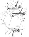
- Fig. 1 shows a formed in the present case as a cuboid cuboid transport body 10 which is provided in its corners with corner fasteners 11, which serve for the connection of container lifting and transport means 12.
- the container lifting and transport devices 12 are connected via a support arm device 13 with two corner fasteners 11 at a high edge 14 of the transport body 10.
- the support arm devices 13 are each connected to a Zahnstangenhub listening 15 which actuated via a crank mechanism 16 allows a lifting movement of the transport body 10.
- the Zahnstangenhub listeningen 15 are provided at its lower end with a mountable wheel device 17.
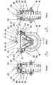
- the wheel device 17 has a wheel axle 18 which is used to receive a wheel 19 in a steering wheel 20 is arranged.
- the axle stool 20 is substantially U-shaped with a Achsschemelbasis 21 and two laterally attached thereto Achsschemelwangen 22, 23, which are each triangular in shape.
- Achsschemelbasis 21 Above the Achsschemelbasis 21 is a support bracket 24 which is provided with a here as a king pin 25 designated Einsteckzapfen serving as a coupling element.
- the kingpin 25 is provided at its end facing the axle stile 20 with a connecting pin 29 ( FIG. 6 ) which serves to connect the carrying bracket 24 to the axle stool 20.
- the wheel device 17 is inserted with the king pin 25 in a trained at the lower end of the rack 15 Zahnstangenhub issued receiving plate 61 and secured with a locking pin 26 extending in the securing position transverse to a kingpin axis 27 engages in an annular groove 28 of the kingpin 25.
- the kingpin 25 of the wheel assembly 17 also with an adapter not shown here are provided by means of the wheel device 17 directly to the lower corner fasteners 11th the transport body 10 can be attached.
- the kingpin axis 27 for forming a wake N a corresponding distance to the wheel axle 18.
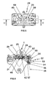
- a damping device 30 is provided, which in present case, two damper assemblies 31, 32, each in spaced from the wheel axle 18 end portions of the Achsschemelbasis 21 and the support bracket 24 are arranged.
- each damper assembly 31 and 32 respectively comprises two damper elements 33 and 34, which are made of a damping rubber.
- the damper 30 facing the underside of the support bracket 24 and the damper 30 facing top of the Achsschemelbasis 21 are formed so that in the defined by the assembly of the support bracket 24 and the Achsschemels 20 relative arrangement between the underside of the support bracket 24 and the top of the Achsschemelbasis 21st four damper chambers 35, 36, 37 and 38 are formed, which each serve to receive a damper element 33 and 34, respectively.
- the here cylindrically shaped damper elements 33 and 34 are biased by acting in the connecting pin 29 between the support bracket 24 and the axle frame 20 tensile stress.
- the kingpin 25 which serves on the one hand as a coupling element for connection to the Zahnstangenhub issued 15 of the container lifting and transporting device 12 and on the other hand with its connecting pin 29 for connecting the support bracket 24 with the Achsschemel 20 , Connected via a mounting flange 39 with a top 40 of the support bracket 24.
- the support bracket 24 is provided with a convertible latch 64 which allows a pivotal locking of the kingpin 25 by a stop against the Zahnstangenhub Road 15, so that the direction of the caster N is locked and defined.
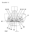
- the passage opening 43 in the axle base 21 is provided with a considerable excess r relative to the diameter of the connecting pin 29, so that an annular gap 48 is formed between the connecting pin 29 and the opening edge 45 of the passage opening 43. in the present case, an elastic damping ring 47 is inserted.
- a drawbar device which is not shown here in detail, for example at drawbar eyes 63 of the support bracket 24, causes a pull action between the kingpin axis 27 and the wheel axle 18 during a start-up or braking operation. or compressive force F, which leads to a corresponding relative movement of the connecting pin 29 transverse to the kingpin axis 27 in the through hole 43. Due to the radial excess r, it is thus possible that not only gravity-related shocks can be absorbed by the damper elements 33 and 34, but also starting and braking shocks.
- the disc 46 is provided in its connection region to the connecting pin 29 with a dome portion 49 which engages in a formed as a Kalottenam 50 front end cross-section of the connecting pin 29.
- the wheel assembly 17 is provided with an eccentric brake 52 which causes an eccentric 55 against a wheel circumference 56 when moving a brake lever 53 about an eccentric axis 54.
- an eccentric brake 52 which causes an eccentric 55 against a wheel circumference 56 when moving a brake lever 53 about an eccentric axis 54.
- the support bracket 24 is provided with a plurality of drawbar eyes 63, which is independent of the respective positioning of the wheel device 17th allow a connection with the drawbar device.
- a suitably trained drawbar device immediately To connect with axle nuts 59 of the wheel axle 18.
Landscapes
- Engineering & Computer Science (AREA)
- Mechanical Engineering (AREA)
- Chemical & Material Sciences (AREA)
- Combustion & Propulsion (AREA)
- Transportation (AREA)
- Handcart (AREA)
- Vehicle Body Suspensions (AREA)
- Forklifts And Lifting Vehicles (AREA)
Abstract
Description
- Fig. 1
- eine Mehrzahl von in Eckbereichen eines Transportkörpers angeordneten Radeinrichtungen;
- Fig. 2
- eine Radeinrichtung in Seitenansicht;
- Fig. 3
- die in Fig. 2 dargestellte Radeinrichtung in einer Ansicht gemäß dem Pfeil III;
- Fig. 4
- die in Fig. 2 dargestellte Radeinrichtung in einer Ansicht gemäß dem Pfeil IV;
- Fig. 5
- eine Draufsicht der in Fig. 2 dargestellten Radeinrichtung;
- Fig. 6
- eine Teilschnittdarstellung der in Fig. 5 dargestellten Radeinrichtung gemäß Schnittlinienverlauf VI-VI;
- Fig. 7
- eine vergrößerte Darstellung des in Fig. 6 mit X gekennzeichneten Bereichs.
Claims (10)
- Anbaubare Radeinrichtung (17) zum Anschluss an einen Transportkörper (10), insbesondere für eine Container-, Hub- und Transporteinrichtung, mit einem gabelförmig ausgebildeten Achsschemel (20) zur Aufnahme einer Radachse (18) eines in den Achsschemel (20) eingesetzten Laufrads (19) und mit einer Tragkonsole (24), die zur Aufnahme eines Kupplungselements (25) zum Anschluss an den Transportkörper und zur Verbindung mit dem Achsschemel dient, sowie einer zwischen der Tragkonsole und dem Achsschemel wirksamen Dämpfungseinrichtung (30).
- Radeinrichtung nach Anspruch 1,
dadurch gekennzeichnet, dass das Kupplungselement (25) zur Verbindung des Achsschemels (20) mit der Tragkonsole (24) dient. - Radeinrichtung nach Anspruch 1 oder 2,
dadurch gekennzeichnet, dass die Dämpfungseinrichtung (30) zumindest zwei Dämpferanordnungen (31, 32) umfasst, die mit Abstand zum Kupplungselement (25) zu beiden Seiten der Radachse (18) angeordnet sind. - Radeinrichtung nach Anspruch 3,
dadurch gekennzeichnet, dass die Dämpferanordnungen (31, 32) jeweils zwei Dämpferelemente (33, 34) umfassen, die mit Abstand in einer Richtung parallel zur Radachse (18) voneinander angeordnet sind. - Radeinrichtung nach Anspruch 4,
dadurch gekennzeichnet, dass die Dämpferelemente (33, 34) als Dämpfungskörper ausgebildet sind. - Radeinrichtung nach einem der vorangehenden Ansprüche,
dadurch gekennzeichnet, dass das Kupplungselement (25) mit seitlichem Abstand zur Radachse (18) angeordnet ist. - Radeinrichtung nach einem der vorangehenden Ansprüche,
dadurch gekennzeichnet, dass das Kupplungselement (25) zur Verbindung mit dem Achsschemel (20) einen Verbindungszapfen (29) aufweist, der bei radial zwischenliegender Anordnung eines Dämpfungselements (33, 34) in eine Verbindungsöffnung (43) des Achsschemels eingesetzt ist. - Radeinrichtung nach Anspruch 7,
dadurch gekennzeichnet, dass zur axialen Vorspannung der zwischen dem Achsschemel (20) und der Tragkonsole (24) angeordneten Dämpferelemente (33, 34) der Verbindungszapfen (29) des Kupplungselements (25) über eine die Verbindungsöffnung (43) des Achsschemels hintergreifende Scheibe (46) mit dem Achsschemel verbunden ist. - Radeinrichtung nach Anspruch 8,
dadurch gekennzeichnet, dass die Scheibe (46) zur Verbindung mit dem Verbindungszapfen (29) einen Kalottenteil (49) aufweist, der in eine stirnseitig am Verbindungszapfen (29) ausgebildete Kalottenaufnahme (50) eingreift. - Radeinrichtung nach einem der vorangehenden Ansprüche,
dadurch gekennzeichnet, dass das Kupplungselement (25) als Einsteckzapfen ausgebildet ist.
Applications Claiming Priority (2)
| Application Number | Priority Date | Filing Date | Title |
|---|---|---|---|
| DE10361126 | 2002-12-12 | ||
| DE2003161126 DE10361126B4 (de) | 2003-12-22 | 2003-12-22 | Anbaubare Radeinrichtung |
Publications (3)
| Publication Number | Publication Date |
|---|---|
| EP1547900A2 true EP1547900A2 (de) | 2005-06-29 |
| EP1547900A3 EP1547900A3 (de) | 2007-06-20 |
| EP1547900B1 EP1547900B1 (de) | 2009-01-21 |
Family
ID=34530394
Family Applications (1)
| Application Number | Title | Priority Date | Filing Date |
|---|---|---|---|
| EP20040003860 Expired - Lifetime EP1547900B1 (de) | 2003-12-22 | 2004-02-20 | Anbaubare Radeinrichtung |
Country Status (2)
| Country | Link |
|---|---|
| EP (1) | EP1547900B1 (de) |
| DE (2) | DE10361126B4 (de) |
Cited By (3)
| Publication number | Priority date | Publication date | Assignee | Title |
|---|---|---|---|---|
| CN106000176A (zh) * | 2016-06-01 | 2016-10-12 | 李明科 | 一种可移动的工业搅拌机 |
| CN106114585A (zh) * | 2016-08-18 | 2016-11-16 | 桐乡市崇福常新玻璃马赛克厂 | 一种马赛克瓷砖用运输装置 |
| WO2021011969A1 (en) * | 2019-07-17 | 2021-01-21 | Van Chanh NGUYEN | Wheel structure for 360-degree rotating building in water tank and 360-degree rotating building in water tank |
Families Citing this family (1)
| Publication number | Priority date | Publication date | Assignee | Title |
|---|---|---|---|---|
| DE202010014784U1 (de) * | 2010-10-29 | 2012-01-30 | Willi Kapfer | Transportvorrichtung für Container |
Citations (5)
| Publication number | Priority date | Publication date | Assignee | Title |
|---|---|---|---|---|
| US2647277A (en) | 1949-01-03 | 1953-08-04 | Roll Rite Corp | Wheel and mounting assembly |
| US3286298A (en) | 1964-12-08 | 1966-11-22 | William J Veary | Caster assembly |
| DE2833330C2 (de) | 1978-07-29 | 1982-12-23 | Paul Vom Stein & Co, 5632 Wermelskirchen | Lenkrolle für Transportkarren, Apparate, Möbel o.dgl. |
| DE9401794U1 (de) | 1993-02-08 | 1994-03-31 | Acla-Werke GmbH, 51147 Köln | Lenkrolle |
| DE20219351U1 (de) | 2002-12-10 | 2003-02-20 | Hsiao, Te-Hsin, Yen Chao, Kaohsiung | Stoßdämpfer für Laufrollen |
Family Cites Families (1)
| Publication number | Priority date | Publication date | Assignee | Title |
|---|---|---|---|---|
| DE29501456U1 (de) * | 1994-02-03 | 1995-03-23 | Acla-Werke GmbH, 51065 Köln | Lenkrolle |
-
2003
- 2003-12-22 DE DE2003161126 patent/DE10361126B4/de not_active Expired - Fee Related
-
2004
- 2004-02-20 EP EP20040003860 patent/EP1547900B1/de not_active Expired - Lifetime
- 2004-02-20 DE DE200450008907 patent/DE502004008907D1/de not_active Expired - Lifetime
Patent Citations (5)
| Publication number | Priority date | Publication date | Assignee | Title |
|---|---|---|---|---|
| US2647277A (en) | 1949-01-03 | 1953-08-04 | Roll Rite Corp | Wheel and mounting assembly |
| US3286298A (en) | 1964-12-08 | 1966-11-22 | William J Veary | Caster assembly |
| DE2833330C2 (de) | 1978-07-29 | 1982-12-23 | Paul Vom Stein & Co, 5632 Wermelskirchen | Lenkrolle für Transportkarren, Apparate, Möbel o.dgl. |
| DE9401794U1 (de) | 1993-02-08 | 1994-03-31 | Acla-Werke GmbH, 51147 Köln | Lenkrolle |
| DE20219351U1 (de) | 2002-12-10 | 2003-02-20 | Hsiao, Te-Hsin, Yen Chao, Kaohsiung | Stoßdämpfer für Laufrollen |
Cited By (4)
| Publication number | Priority date | Publication date | Assignee | Title |
|---|---|---|---|---|
| CN106000176A (zh) * | 2016-06-01 | 2016-10-12 | 李明科 | 一种可移动的工业搅拌机 |
| CN106114585A (zh) * | 2016-08-18 | 2016-11-16 | 桐乡市崇福常新玻璃马赛克厂 | 一种马赛克瓷砖用运输装置 |
| CN106114585B (zh) * | 2016-08-18 | 2018-08-14 | 郭冬青 | 一种马赛克瓷砖用运输装置 |
| WO2021011969A1 (en) * | 2019-07-17 | 2021-01-21 | Van Chanh NGUYEN | Wheel structure for 360-degree rotating building in water tank and 360-degree rotating building in water tank |
Also Published As
| Publication number | Publication date |
|---|---|
| DE10361126A1 (de) | 2005-07-21 |
| EP1547900A3 (de) | 2007-06-20 |
| EP1547900B1 (de) | 2009-01-21 |
| DE502004008907D1 (de) | 2009-03-12 |
| DE10361126B4 (de) | 2006-06-01 |
Similar Documents
| Publication | Publication Date | Title |
|---|---|---|
| DE69616415T2 (de) | Faltenbalg sowie Luftfeder-Aufhängungssystem und Achsanhebesystem | |
| DE69501940T2 (de) | Abnehmbare Befestigung eines Fahrzeugsitzuntergestells auf einem Boden | |
| EP3473506A1 (de) | Stützvorrichtung für ein fahrzeug | |
| DE102017218796A1 (de) | Achsaufhängung | |
| EP1547900A2 (de) | Anbaubare Radeinrichtung | |
| EP1107891B1 (de) | Stützfuss | |
| DE68915877T2 (de) | Strasseneinheit mit absetzbarer Trägerkarosserie. | |
| DE102007050646A1 (de) | Gepäckträger für ein Fahrzeug | |
| CH683127A5 (de) | Winkelsensor für den Winkel zwischen den Längsachsen eines Zugfahrzeugs und eines Anhängers. | |
| DE10202778B4 (de) | Bremsträgeranordnung | |
| DE102010053083A1 (de) | Sattelkupplung mit einstellbarer Höhe | |
| DE69101000T2 (de) | Hebbare Ladebordwand mit einem Anschlag zum Halten einer Transportkarre auf ihrer Plattform. | |
| EP0501150B1 (de) | Kraftfahrzeug mit einer Anhängevorrichtung | |
| DE202017106296U1 (de) | Stützvorrichtung für ein Fahrzeug | |
| DE2752799C3 (de) | Elastische Lagerung eines unteren Dreieckslenkers einer Kraftfahrzeug-Vorderradaufhängung | |
| DE68911823T2 (de) | Karosserieteil für eine Fahrerhaus eines Lastkraftwagens mit integrierter Trittstufe. | |
| DE102019007631A1 (de) | Pedalvorrichtung für eine Bremsanlage eines Kraftfahrzeugs | |
| DE102007006265A1 (de) | Sattelzugmaschine eines Sattelkraftwagens | |
| EP2284041A1 (de) | Tritthalterung | |
| DE102006007129A1 (de) | Sattelkupplung zur Verbindung einer Sattelzugmaschine mit einem Sattelauflieger | |
| DE102017218795A1 (de) | Achsaufhängung | |
| DE102009021459A1 (de) | Rahmenelement für einen Fahrzeugrahmen | |
| EP3611083B2 (de) | Kupplungsplatte für eine sattelkupplung | |
| DE102018109814B4 (de) | Deichsel und Fahrzeuganhänger | |
| DE102018006572B4 (de) | Fahrzeugaufhängungsanordnung für mindestens eine Radachse |
Legal Events
| Date | Code | Title | Description |
|---|---|---|---|
| PUAI | Public reference made under article 153(3) epc to a published international application that has entered the european phase |
Free format text: ORIGINAL CODE: 0009012 |
|
| AK | Designated contracting states |
Kind code of ref document: A2 Designated state(s): AT BE BG CH CY CZ DE DK EE ES FI FR GB GR HU IE IT LI LU MC NL PT RO SE SI SK TR |
|
| AX | Request for extension of the european patent |
Extension state: AL LT LV MK |
|
| PUAL | Search report despatched |
Free format text: ORIGINAL CODE: 0009013 |
|
| AK | Designated contracting states |
Kind code of ref document: A3 Designated state(s): AT BE BG CH CY CZ DE DK EE ES FI FR GB GR HU IE IT LI LU MC NL PT RO SE SI SK TR |
|
| AX | Request for extension of the european patent |
Extension state: AL LT LV MK |
|
| RIC1 | Information provided on ipc code assigned before grant |
Ipc: B62B 5/00 20060101AFI20041025BHEP Ipc: B60B 33/04 20060101ALI20070511BHEP |
|
| 17P | Request for examination filed |
Effective date: 20070726 |
|
| 17Q | First examination report despatched |
Effective date: 20071123 |
|
| AKX | Designation fees paid |
Designated state(s): DE FR GB |
|
| GRAP | Despatch of communication of intention to grant a patent |
Free format text: ORIGINAL CODE: EPIDOSNIGR1 |
|
| GRAS | Grant fee paid |
Free format text: ORIGINAL CODE: EPIDOSNIGR3 |
|
| GRAA | (expected) grant |
Free format text: ORIGINAL CODE: 0009210 |
|
| AK | Designated contracting states |
Kind code of ref document: B1 Designated state(s): DE FR GB |
|
| REG | Reference to a national code |
Ref country code: GB Ref legal event code: FG4D Free format text: NOT ENGLISH |
|
| REF | Corresponds to: |
Ref document number: 502004008907 Country of ref document: DE Date of ref document: 20090312 Kind code of ref document: P |
|
| PLBE | No opposition filed within time limit |
Free format text: ORIGINAL CODE: 0009261 |
|
| STAA | Information on the status of an ep patent application or granted ep patent |
Free format text: STATUS: NO OPPOSITION FILED WITHIN TIME LIMIT |
|
| 26N | No opposition filed |
Effective date: 20091022 |
|
| PGFP | Annual fee paid to national office [announced via postgrant information from national office to epo] |
Ref country code: FR Payment date: 20140218 Year of fee payment: 11 |
|
| PGFP | Annual fee paid to national office [announced via postgrant information from national office to epo] |
Ref country code: GB Payment date: 20140220 Year of fee payment: 11 |
|
| PGFP | Annual fee paid to national office [announced via postgrant information from national office to epo] |
Ref country code: DE Payment date: 20140424 Year of fee payment: 11 |
|
| REG | Reference to a national code |
Ref country code: DE Ref legal event code: R119 Ref document number: 502004008907 Country of ref document: DE |
|
| GBPC | Gb: european patent ceased through non-payment of renewal fee |
Effective date: 20150220 |
|
| REG | Reference to a national code |
Ref country code: FR Ref legal event code: ST Effective date: 20151030 |
|
| PG25 | Lapsed in a contracting state [announced via postgrant information from national office to epo] |
Ref country code: GB Free format text: LAPSE BECAUSE OF NON-PAYMENT OF DUE FEES Effective date: 20150220 Ref country code: DE Free format text: LAPSE BECAUSE OF NON-PAYMENT OF DUE FEES Effective date: 20150901 |
|
| PG25 | Lapsed in a contracting state [announced via postgrant information from national office to epo] |
Ref country code: FR Free format text: LAPSE BECAUSE OF NON-PAYMENT OF DUE FEES Effective date: 20150302 |