EP1547827A2 - Unité de capture autoalimenté et system de surveillance de pneumatiques utilisant cette unité - Google Patents
Unité de capture autoalimenté et system de surveillance de pneumatiques utilisant cette unité Download PDFInfo
- Publication number
- EP1547827A2 EP1547827A2 EP04257189A EP04257189A EP1547827A2 EP 1547827 A2 EP1547827 A2 EP 1547827A2 EP 04257189 A EP04257189 A EP 04257189A EP 04257189 A EP04257189 A EP 04257189A EP 1547827 A2 EP1547827 A2 EP 1547827A2
- Authority
- EP
- European Patent Office
- Prior art keywords
- sensor
- self
- sensing module
- signal
- power
- Prior art date
- Legal status (The legal status is an assumption and is not a legal conclusion. Google has not performed a legal analysis and makes no representation as to the accuracy of the status listed.)
- Granted
Links
Images


Classifications
-
- B—PERFORMING OPERATIONS; TRANSPORTING
- B60—VEHICLES IN GENERAL
- B60C—VEHICLE TYRES; TYRE INFLATION; TYRE CHANGING; CONNECTING VALVES TO INFLATABLE ELASTIC BODIES IN GENERAL; DEVICES OR ARRANGEMENTS RELATED TO TYRES
- B60C23/00—Devices for measuring, signalling, controlling, or distributing tyre pressure or temperature, specially adapted for mounting on vehicles; Arrangement of tyre inflating devices on vehicles, e.g. of pumps or of tanks; Tyre cooling arrangements
- B60C23/02—Signalling devices actuated by tyre pressure
- B60C23/04—Signalling devices actuated by tyre pressure mounted on the wheel or tyre
- B60C23/0408—Signalling devices actuated by tyre pressure mounted on the wheel or tyre transmitting the signals by non-mechanical means from the wheel or tyre to a vehicle body mounted receiver
- B60C23/041—Means for supplying power to the signal- transmitting means on the wheel
- B60C23/0411—Piezoelectric generators
Definitions
- the present invention concerns a self-powered sensing module capable of operating without having to use separate power supplied externally and a tire pressure monitoring system using the sensing module.
- a tire for a wheeled vehicle generally transfers driving power, brake power, and lateral force of the vehicle onto a road while supporting the load of the vehicle against the road, and also serves as a spring and a damper for absorbing shock and impact with respect to the road.
- a tire pressure is above a suitable range, the vehicle tramps over the road to cause ride discomfort and acceleration of the abrasion of the tire. If the tire pressure is below the suitable range, acceleration of the abrasion of the tire occurs as well and this condition may also bring about a traffic accident due to a puncture occurring to the tire during driving. In addition, the driving of the vehicle deteriorates and fuel efficiency decreases. Accordingly, it is essential to maintain the suitable tire pressure.
- TPMS tire pressure monitoring system
- FIG. 1 depicts an example of a conventional TPMS 12.
- the TPMS 12 includes four pressure sensing modules 15a, 15b,15c and 15d and a main unit 17.
- the pressure sensing modules 15a, 15b, 15c and 15d are mounted in tires 13a, 13b, 13c and 13d, respectively.
- the main unit 17 is secured in a body of a vehicle 11.
- each of the pressure sensing modules 15a, 15b, 15c and 15d includes a pressure sensor 21, a transmission circuit 22, a battery 23, and a transmission antenna 24.
- the battery 23 may be a lithium battery and supplies power to the pressure sensor 21 and the transmission circuit 22.
- the transmission antenna 24 irradiates a radio wave within a radius of the tire 13a, 13b, 13c or 13d.
- the pressure sensor 21 communicates with the transmission circuit 22 which is connected to the transmission antenna 24 through an output terminal 25.
- the pressure sensor 21 detects the pressure in the tire 13a, 13b, 13c or 13d and transmits to the transmission circuit 22 a signal carrying information on the detected pressure.
- the transmission circuit 22 is provided with an internal memory (not shown) storing a unique identification (ID) code.
- ID code is to identify the pressure sensing modules 15a, 15b, 15c and 15d mounted in the vehicle 11 from each other.
- the transmission circuit 22 performs modulation in order to generate a signal carrying data indicating the pressure information and the ID code, and transmits the modulated signal as the radio wave over the transmission antenna 24.
- the main unit 17 includes four reception antennae 31a, 31b, 31c and 31 d, a reception circuit 33, a controller 34, and a display 18.
- the reception circuit 33 receives via the reception antennae 31a, 31b, 31c and 31d the radio wave from the transmission antenna 24 of the pressure sensing modules 15a, 15b, 15c and 15d.
- the reception circuit 33 detects and demodulates the radio wave carrying the pressure data, and transfers the demodulated data to the controller 24.
- the controller 34 controls the display 18 to display information on the tire pressure based on the received data.
- the display 18 is mounted at a cockpit and is connected with the controller 34.
- the conventional TPMS 12 has a disadvantage that the vehicle operator needs to replace the battery 23 by separating each of the tires 13a, 13b, 13c and 13d when the battery 23 is run down for supplying the power to the pressure sensor 21 of the pressure sensing module 15a, 15b, 15c or 15d and the transmission circuit 22. This is because the pressure sensing modules 15a, 15b, 15c and 15d are mounted in the tires 13a, 13b, 13c and 13d, respectively.
- the lithium battery 23 Since the lithium battery 23 is expensive, it costs a lot to maintain the TPMS 12.
- the pressure sensing modules 15a, 15b, 15c and 15d which are mounted in the tires 13a, 13b, 13c and 13d, increase in volume due to the size of the lithium battery 23.
- TPMS which estimates the pressure of the tire by measuring elasticity of the tire from the suspension of the vehicle, instead of measuring the pressure in the tires 13a, 13b, 13c and 13d.
- Such a TPMS overcomes the above disadvantage of separating the tires in order to replay the battery.
- the TPMS has a drawback that it is hard to obtain accurate tire pressure since the tire pressure is estimated based on the elasticity of the tires.
- TPMS tire pressure monitoring system
- the invention thus provides a tire pressure monitoring system which is powered by a power unit generating the power owing to mechanical deformation, without using a separate power supply. Accordingly, there is no need to replace the battery of the sensing module and maintenance costs are reduced.
- the power unit may comprise a power generator generating the power by mechanically deforming by the tires; and a power converter converting the power generated in the power generator to a power required for the sensor and the transmitter unit.
- the power generator is preferably a piezoelectric generator which uses the direct piezoelectric effect of a piezoelectric material which generates voltage when bent or when stress is given.
- the piezoelectric generator may comprise piezoelectric thin film first and second electrodes formed on and below the piezoelectric thin film to face each other, and a flexible cover member attached on an outer surface of one of the first and second electrodes for flexibly supporting and protecting the piezoelectric thin film.
- the piezoelectric thin film comprises a plurality of first and second piezoelectric elements disposed at certain intervals in alternation and polarized into an anode and a cathode; and a plurality of piezoelectric pads disposed between the first and second piezoelectric elements and separating the first and second piezoelectric elements from each other.
- the power converter may comprise an AC/DC converter converting alternate current (AC) generated in the power generator to direct current (DC); and a DC/DC converter converting the DC converted in the AC/DC converter to the power required for the sensor and the transmitter unit.
- AC alternate current
- DC direct current
- the transmitter unit may comprise a transmission control unit amplifying a sensing signal output from the sensor to a certain level and outputting the amplified signal in a predetermined format at predetermined intervals; and a transmission output unit transmitting the data signal output from the transmission controller to the outside.
- the transmission controller preferably comprises a sensing signal amplifier amplifying the sensing signal output from the sensor to the certain level; an analog-to-digital (A/D) converter converting an amplified analog signal of the sensing signal amplifier to a digital signal; and a transmission controller receiving the digital signal output from the A/D converter and outputting the received signal together with an identification (ID) code of the individual tire and the individual sensor in the predetermined data format at the predetermined time intervals.
- A/D analog-to-digital
- the transmission output unit may comprise a frequency generator generating a predetermined carrier frequency; and a radio frequency (RF) generator modulating the data signal output from the transmission controller and emitting the modulated signal as a radio wave through a transmission antenna.
- RF radio frequency
- the receiver unit may comprise a reception amplifier amplifying the data signal transmitted from the transmitter unit in the predetermined data format, to a certain level; and a detector demodulating or detecting the data signal amplified in the reception amplifier and outputting the demodulated or detected signal.
- the monitoring unit can comprise a main controller receiving the detected signal from the detector, confirming a corresponding tire and sensor by comparing the received signal with a pre-input ID code signal of the individual tire and the individual sensor, and controlling to display a confirmation result; and a display displaying the confirmation result according to a control signal of the main controller.
- the main controller compares the data of the confirmed sensor with a pre-input specified data of the sensor and controls to generate an alarm signal if the comparison result is out of an allowable range.
- the monitoring unit further comprises a speaker for generating an alarm according to the alarm signal of the main controller.
- the self-powered sensing module is preferably disposed on an inner bottom of the tire.
- the self-powered sensing module further comprises an elastic fixing member facilitating attachment onto an inner bottom of the tire.
- the invention also provides a self-powered sensing module comprising:
- the power unit may comprise a power generator generating the power by being mechanically deformed by the object; and a power converter converting the power generated in the power generator to a power required for the sensor.
- the power generator can comprises a piezoelectric generator.
- the piezoelectric generator comprises a piezoelectric thin film; first and second electrodes formed on and below the piezoelectric thin film to face each other; and a flexible cover member attached on an outer surface of at least one of the first and second electrodes for flexibly supporting and protecting the piezoelectric thin film.
- the piezoelectric thin film comprises a plurality of first and second piezoelectric elements disposed at certain intervals in alternation and polarized into an anode and a cathode; and a plurality of piezoelectric pads disposed between the first and second piezoelectric elements and separating the first and second piezoelectric elements from each other.
- the power converter may comprise an AC/DC converter converting alternate current (AC) generated in the power generator to direct current (DC); and a DC/DC converter converting the DC converted in the AC/DC converter to the power required for the sensor.
- AC alternate current
- DC direct current
- the self-powered sensing module may further comprise a transmitter unit transmitting data measured by the sensor of the sensor unit to the outside.
- the transmitter unit preferably comprises a transmission control unit amplifying a sensing signal output from the sensor to a certain level and outputting the amplified signal in a predetermined format at predetermined intervals; and a transmission output unit transmitting the data signal output from the transmission controller to the outside.
- the transmission control unit may comprise a sensing signal amplifier amplifying the sensing signal output from the sensor to the certain level; an analog-to-digital (A/D) converter converting an amplified analog signal of the sensing signal amplifier to a digital signal; and a transmission controller receiving the digital signal output from the A/D converter and outputting the received signal together with an identification (ID) code of the individual tire and the individual sensor in the predetermined data format at the predetermined time intervals.
- A/D analog-to-digital
- the transmission output unit may comprise a frequency generator generating a predetermined carrier frequency; and a radio frequency (RF) generator modulating the data signal output from the transmission controller and emitting the modulated signal as a radio wave through a transmission antenna.
- RF radio frequency
- the object measured by the sensor can be a tire for a vehicle, and the self-powered sensing module is then disposed on an inner bottom of the tire.
- FIG. 4 is a schematic illustrating a tire pressure monitoring system (TPMS) employing self-powered sensing modules for a wheeled vehicle according to an exemplary embodiment of the present invention.
- TPMS tire pressure monitoring system
- the TPMS 112 includes four self-powered sensing module 115a, 115b, 115c and 115d installed in four tires 113a, 113b, 113c and 113d, respectively, and a main unit 117 installed in a vehicle body 111.
- the self-powered sensing modules 115a, 115b, 115c and 115d are installed on an inner bottom 172 (FIGS. 7B and 7C) of the tires 113a, 113b, 113c and 113d, respectively, in order to protect from damage due to shock against a road 170.
- each of the powered sensing modules 115a, 115b, 115c and 115d includes an elastic fixing member 151, a sensor unit 130, a power unit 120, and a transmitter unit 140.
- the elastic fixing member 151 is attached onto the inner bottom 172 of the tires 113a, 113b,113c and 113d and formed with a rubber material.
- the sensor unit 130 is mounted on a board 152 attached onto an inner side 151a of the elastic fixing member 151, and includes a pressure sensor 131, a temperature sensor 133, and an acceleration sensor 135 (FIG. 8) for measuring pressure, temperature, and acceleration within the tires 113a, 113b, 113c and 113d.
- the power unit 120 is mounted on the inner side 151 a of the elastic fixing member 151 and on an inner side 152a of the board 152, and generates power by being deformed mechanically by the tires 113a, 113b, 113c and 113d while the tires 113a, 113b, 113c and 113d revolve, and supplies the sensors 131, 133 and 135 with the power required for operating the sensors 131, 133 and 135 of the sensor unit 130.
- the transmitter unit 140 is mounted on the inner side 152a of the board 152 and transmits data detected by the sensors 131, 133 and 135 to the outside.
- the sensor unit 130 is configured with a single circuit board (not shown) on which the pressure sensor 131, the temperature sensor 133, and the acceleration sensor 135 are systemized and mounted, or an integrated sensor by implementing the pressure sensor 131, and the temperature sensor 133 and the acceleration sensor 135 as a single chip by use of MEMS (Micro Electro Mechanical System).
- MEMS Micro Electro Mechanical System
- the circuit board or the integrated sensor forming the sensor unit 130 is sealed by a sensor casing 130a to protect it from external shock and impact.
- the power unit 120 includes a power generator 121 and a power conversion unit 125.
- the power generator 121 is attached onto the inner side 151a of the elastic fixing member 151, and generates power by deforming mechanically according to the corresponding tires 113a, 113b, 113c and 113d.
- the power conversion unit 125 is disposed on the inner side 152a of the board 152, and converts the power generated in the power generator 121 to a power required for the pressure sensor 131, the temperature sensor 133, and the acceleration sensor 135 of the sensor unit 130, and a transmission controller 143 and a frequency generator 146 of the transmitter unit 140, which will be explained below.
- the power generator 121 is a piezoelectric generator using direct piezoelectric effect of a piezoelectric material which generates voltage when bent or when stress is applied.
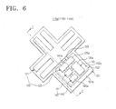
- the piezoelectric generator is in an overlapped H-shaped form, as shown in FIGS. 7B and 7C, in order to effectively react to the given bending or stress, and includes a piezoelectric thin film 123, first and second electrode plates 122 and 128, and a flexible cover member 129.
- the electronic thin film 123 is formed in thickness of 0.5-2.0 ⁇ m by use of the piezoelectric material such as Zno, PZT(Pb(ZrTi)O 3 ) and PLZT((PbLa)(ZrTi) O 3 ).
- the first and second electrode plates 122 and 128 respectively form an anode and a cathode, and are formed in thickness of 0.1-1.0 ⁇ m by use of a metal such as Pt, Ta, and Pt-Ta facing each other on and below the piezoelectric thin film 123.
- the flexible cover member 129 is attached onto an outer surface of the second electrode plate 128 for protecting the piezoelectric thin film 123.
- the piezoelectric thin film 123 includes a plurality of first and second piezoelectric elements 123a and 123b polarizing into an anode and a cathode.
- the first and second piezoelectric elements 123a and 123b are disposed at certain intervals in alternation, and a plurality of piezoelectric pads 124 are disposed between the first and second piezoelectric elements 123a and 123b for separating from the first and second piezoelectric elements 123a and 123b.
- the piezoelectric thin film 123 (shown in FIGS. 7B, 7C) of the power generator 121, which are attached onto the inner bottom 172 of tires 113a, 113b, 113c and 113d through the elastic fixing member 151, is pressed and deformed. Then, the deformed first and second piezoelectric elements 123a and 123b generate electromotive force of the plus and minus polarities in alternation.
- the electromotive force of the plus and minus polarities which is generated in the first and second piezoelectric elements 123a and 123b, is applied to the power conversion unit 125 through first and second connection terminals 153a and 153b connected to the first and second electrode plates 122 and 128, and a wire 153.
- the power conversion unit 125 includes an AC/DC converter 126 and a DC/DC converter 127.
- the AC/DC converter 126 converts alternating current (AC) voltage generated in the power generator 121 to direct current (DC) voltage.
- the DC/DC converter 127 converts the DC voltage converted in the AC/DC converter 126 to the voltage required for the parts of the self-powered sensing modules 115a, 115b, 115c and 115d, specifically, required for the pressure sensor 131, the temperature sensor 133 and the acceleration sensor 135 of the sensor unit 130, the transmission controller 143 and the frequency generator 146 of the transmitter unit 140.
- the voltage converted by the DC/DC converter 127 is supplied directly to the parts of the self-powered sensing modules 115a, 115b, 115c and 115d in this exemplary embodiment, but not by way of limitation.
- the converted voltage may be stored in a storage battery (not shown) and then supplied to the parts of the self-powered sensing modules 115a, 115b, 115c and 115d in order to operate the self-powered sensing modules 115a, 115b, 115c and 115d even when the vehicle stands still.
- the power converter 125 like the circuit board or the integrated sensor of the sensor unit 130, is sealed by a power converter casing 125a to protect from external shock and impact.
- the transmitter unit 140 includes a transmission control unit 141 and a transmission output unit 145.
- the transmission control unit 141 amplifies voltages output from the pressure sensor 131, the temperature sensor 133 and the acceleration sensor 135, that is, amplifies sensing signals to a certain level and outputs the amplified signals in sequence at predetermined time intervals and in a predetermined format.
- the transmission output unit 145 transmits a data signal output from the transmission control unit 141 to an output side.
- the transmission control unit 141 includes a sensing signal amplifier 136, a switch 144, an analog-to-digital (A/D) converter 142, and the transmission controller 143.
- the sensing signal amplifier 136 includes first, second and third amplifiers 137, 138 and 139 amplifying sensing signals output from the pressure sensor 131, and the temperature sensor 133 and the acceleration sensor 135 to a certain level.
- the switch 144 selectively outputs the sensing signals amplified in the first, second and third amplifiers 137, 138 and 139.
- the A/D converter 142 converts the analog signal selectively output from the switch 144 to a digital signal.
- the transmission controller 143 controls a switch operator 148 for the switch 144 to selectively output the sensing signals at predetermined time intervals, and receives and outputs the digital signal output from the A/D converter 142 together with the ID code, which is input in advance and identifies the tires 113a, 113b, 113c and 113d and the signals of the sensors 131, 133 and 135, in a predetermined data format.
- the transmission controller 143 is provided with a first internal memory (not shown) storing the ID code and the data format.
- the transmission controller 143 outputs first, second and third switching actuating signals at predetermined time intervals to the switch operator 148 so as to control to selectively output the sensing signals.
- the switch operator 148 actuates the switch 144 by generating a switching signal at predetermined time intervals according to the first, second and third switching actuating signals.
- the transmission controller 143 It is advantageous to set the time intervals of the generation of the first, second and third switching actuating signals in the transmission controller 143 so as to separately transmit to a receiver unit 160 the sensing signals of the sensors 131, 133 and 135 of the individual self-powered sensing module 115a, 115b, 115c and 115d mounted in the tires 113a, 113b, 113c and 113d. If the sensing signals are transmitted to the receiver unit 160 at the same time, the receiver unit 160 needs to have a reception antenna respectively for the each of the self-powered sensing modules 115a, 115b, 115c and 115d to receive the sensing signals. In addition, the receiver unit 160 needs to have additional switch and switch operator for selectively receiving the sensing signals.
- the receiver unit 160 may include four reception antennae for receiving the sensing signals, and additional switch and switch operator for selectively receiving the sensing signals.
- the transmission output unit 145 includes the frequency generator 146 generating a predetermined carrier frequency and a radio frequency (RF) generator 147 modulating the data signal output in the predetermined data format from the transmission controller 143 and emitting the modulated signal as the radio wave via a transmission antenna 150.
- RF radio frequency
- the transmission control unit 141 and the transmission output unit 145 are sealed in a transmission control unit casing 141a and a transmission output unit casing 145a, respectively, and therefore, protected from external shock and impact.
- the main unit 117 of the TPMS 112 which is mounted in the vehicle body 111, includes the receiver unit 160 and a monitoring unit 169.
- the receiver unit 160 receives the radio wave emitted from the RF generator 147 of the transmitter unit 140.
- the monitoring unit 169 detects and demodulates the radio wave received by the receiver unit 160 and displays to the vehicle operator the corresponding tires 113a, 113b, 113c and 113d and the sensing data of the sensors 113, 133 and 135.
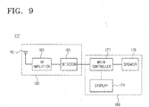
- the receiver unit 160 includes a reception antenna 161 disposed in the vehicle body 111 and receiving the radio wave emitted from the RF generator 147 of the transmitter unit 140 through the transmission antenna 150, a RF amplifier 163 amplifying the radio wave received to the reception antenna 161 to a certain level, and a detector 165 demodulating or detecting and outputting the amplified signal of the RF amplifier 163.
- the monitoring unit 169 includes a main controller 171, a display 174, and a speaker 176.
- the main controller 171 compares the detected signal of the detector 165 with the pre-input ID code signal of the individual tire 113a, 113b, 113c and 113d and the sensors 131, 133 and 135, and confirms that the detected signal is the data of the tires 113a, 113b, 113c and 113d and the sensors 131, 133 and 135.
- the monitoring unit 169 controls to display the confirmation result, compares the confirmed data of the sensors 131, 133 and 135 with a pre-input specified data of the corresponding sensor 131, 133 and 135, and controls to generate an alarm signal if the comparison result is out of an allowable range.
- the display 174 displays the confirmation result according to the signal of the main controller 171.
- the speaker 176 sounds an alarm according to the alarm signal of the main controller 171.
- the main controller 171 includes a second internal memory (not shown) storing the ID code signal of the individual tires 113a, 113b, 113c and 113d and the sensors 131, 133 and 135 and the specified data of the individual sensor 131, 133 and 135.
- the main controller 171 uses the data of the temperature sensor 133 and the acceleration sensor 135 among the confirmed data, for the compensation of temperature and acceleration characteristics of the pressure sensor 131.
- the self-powered sensing modules 115a, 115b, 115c and 115d are protected from the external shock and impact since the power conversion unit 125, the sensor unit 130, the transmission control unit 141, and the transmission output unit 145 are sealed in the power converter casing 125a, the sensor casing 130a, the transmission control unit casing 141a, and the transmission output unit casing 145a, respectively.
- these elements may be sealed in a single casing.
- the self-powered sensing modules 115a, 115b, 115c and 115d is not limited to the TPMS for the vehicles, but may be applied to various devices in which a specific object deforms.
- the self-powered sensing module may be utilized in a safety diagnosis system installed at a bridge having severe vibrations due to running vehicles, thus measuring pressure, temperature, and acceleration.
- the self-powered sensing modules 115a, 115b, 115c and 115d may additionally include other sensors such as a humidity sensor.
- the tires 113a, 113b, 113c and 113d contract in contact with the road 170 and expand apart from the road 170 over again.
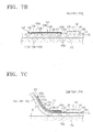
- the piezoelectric thin film 123 of the power generator 121 of the individual self-powered sensing module 115a, 115b, 115c and 115d on the inner bottom 172 of the tires 113a, 113b, 113c and 113d deforms in a certain angle ⁇ in accordance with the tires 113a, 113b, 113c and 113d as shown in FIG. 7C just before and after the tires 113a, 113b, 113c and 113d contact with the road 170.
- the piezoelectric thin film 123 becomes flat again as shown in FIG. 7B.
- the piezoelectric thin film 123 bends as before.
- the first or second piezoelectric element 123a or 123b of the piezoelectric thin film 123 generates the electromotive force of the plus and minus polarities in alternation by the piezoelectric effect.
- the generated electromotive force of the plus and minus polarities is applied to the AC/DC converter 126 of the power conversion unit 125 through the first and second connection terminals 123a and 123b and the wire 153.
- the voltage applied from the power generator 121 is converted to the DC voltage in the AC/DC converter 126 and applied to the DC/DC converter 127.
- the DC/DC converter 127 converts the applied DC voltage to the predetermined voltage and supplies to the parts of the self-powered sensing module 115a, 115b, 115c and 115d, specifically, to the sensors 131, 133 and 135 of the sensor unit 130, the transmission controller 143 of the transmitter unit 140, and the RF generator 146.
- the pressure sensor 131, the temperature sensor 133, and the acceleration sensor 135 detect the pressure, the temperature, and the acceleration in the tires 113a, 113b, 113c and 113d, respectively, and outputs the detected pressure, temperature, and acceleration signals.
- the first, second and third amplifiers 137, 138 and 139 amplify to a certain level the input pressure, temperature, and acceleration signals.
- the transmission controller 143 outputs the first, second and third switching actuating signals to the switch operator 148 at the predetermined intervals.
- the switch operator 148 actuates the switch 144 by generating the switching signal depending on the first, second and third switching actuating signals.
- the switch 144 outputs the signals input from the first, second and third amplifiers 137, 138 and 139 in sequence at the predetermined time intervals.
- the A/D converter 142 converts to the digital signal the analog signal sequentially output from the switch 144 and outputs it to the transmission controller 143.
- the transmission controller 143 Upon receiving the digital signal from the A/D converter 142, the transmission controller 143 combines the digital signal with the ID code, which is pre-input or pre-stored to the first internal memory to distinguish the individual tire 113a, 113b, 113c and 113d and the signals of the sensors 131, 133 and 135, and outputs it in the predetermined data format.
- the frequency generator 146 generates and outputs the predetermined carrier frequency to the RF generator 147.
- the RF generator 147 modulates the output data of the transmission controller 143 and emits the modulated data together with the carrier frequency of the frequency generator 146 as the radio wave through the transmission antenna 150.
- the RF amplifier 163 amplifies the received radio wave to the certain level and outputs the amplified signal to the detector 165.
- the detector 165 detects and outputs the amplified signal to the main controller 171.
- the main controller 171 Upon receiving the detected data signal from the detector 165, the main controller 171 compares the ID code signal, which is carried by the received signal and distinguishes the tires 113a, 113b, 113c and 113d and the signals of the sensors 131,133 and 135, with the ID code signal data of the tires and the sensors pre-input or pre-stored in the second internal memory. Then, the main controller 171 confirms that the data of the received signal concerns one of the tires 113a, 113b, 113c and 113d and one of the sensors 131, 133 and 135, and stores in the second internal memory the confirmed data regarding the pressure, the temperature, and the acceleration.
- the main controller 171 compensates for the pressure according to the temperature and the acceleration of the confirmed tire 113a, 113b, 113c or 113d and controls to update and display the temperature and/or the acceleration of the confirmed tire 113a, 113b, 113c or 113d and the compensated pressure.
- the display 174 displays the temperature and/or the acceleration of the confirmed tire 113a, 113b, 113c or 113d and the compensated pressure according to the control signal of the main controller 171.
- the main controller 171 compares the temperature and/or the acceleration of the confirmed tire 113a, 113b, 113c or 113d and the compensated pressure with data on specified pressure, temperature and/or acceleration pre-input or pre-stored in the second external memory. If the former is out of the allowable range of the latter, the main controller 171 controls to display abnormal state and generates the alarm signal.
- the display 174 displays the abnormal state according to the control signal of the main controller 171.
- the speaker 176 generates the alarm according to the alarm signal of the main controller 171.
- the main controller 171 repeats to confirm the pressure, the temperature, and the acceleration with respect to the individual tire 113a, 113b, 113c and 113d during the rotation of the tires 113a, 113b, 113c and 113d, update and display the confirmed temperature and/or acceleration and the compensated pressure, compare with the specified data, and inform the vehicle operator of the abnormal state through the display 174 and the speaker 176.
- the self-powered sensing module and the TPMS using the same are powered by the power unit generating the power owing to the mechanical deformation without having to use the separate power supply. Hence, there is no need to replace the battery of the sensing module, and the maintenance cost reduces.
- the TPMS employing the self-powered sensing module includes the power unit generating the power depending on the movement of the tires, that is, the running of the vehicle.
Landscapes
- Engineering & Computer Science (AREA)
- Mechanical Engineering (AREA)
- Measuring Fluid Pressure (AREA)
- Arrangements For Transmission Of Measured Signals (AREA)
Applications Claiming Priority (2)
| Application Number | Priority Date | Filing Date | Title |
|---|---|---|---|
| KR1020030094448A KR100555659B1 (ko) | 2003-12-22 | 2003-12-22 | 자가발전형 센싱 모듈 및 그것을 사용하는 타이어 공기압모니터링 시스템 |
| KR2003094448 | 2003-12-22 |
Publications (3)
| Publication Number | Publication Date |
|---|---|
| EP1547827A2 true EP1547827A2 (fr) | 2005-06-29 |
| EP1547827A3 EP1547827A3 (fr) | 2006-08-30 |
| EP1547827B1 EP1547827B1 (fr) | 2009-06-10 |
Family
ID=34545886
Family Applications (1)
| Application Number | Title | Priority Date | Filing Date |
|---|---|---|---|
| EP04257189A Expired - Lifetime EP1547827B1 (fr) | 2003-12-22 | 2004-11-19 | Unité de capture autoalimenté et system de surveillance de pneumatiques utilisant cette unité |
Country Status (5)
| Country | Link |
|---|---|
| US (1) | US7183937B2 (fr) |
| EP (1) | EP1547827B1 (fr) |
| JP (1) | JP4150717B2 (fr) |
| KR (1) | KR100555659B1 (fr) |
| DE (1) | DE602004021464D1 (fr) |
Cited By (10)
| Publication number | Priority date | Publication date | Assignee | Title |
|---|---|---|---|---|
| WO2007099160A1 (fr) * | 2006-03-02 | 2007-09-07 | Continental Teves Ag & Co. Ohg | Module de pneu à transducteur piézoélectrique |
| CN101947905A (zh) * | 2010-08-09 | 2011-01-19 | 哈尔滨工程大学 | 汽车轮胎温度压力监测系统的定位发射装置及方法 |
| EP2415619A1 (fr) | 2010-08-05 | 2012-02-08 | Bridgeport S.R.L. | Module de détection autoalimenté et système de surveillance de l'état des pneus d'un véhicule doté d'au moins un module de détection autoalimenté |
| US8166809B2 (en) | 2006-09-20 | 2012-05-01 | Michelin Recherche et Techinque | In-tire multi-element piezoelectric sensor |
| DE102007007016B4 (de) * | 2006-02-08 | 2016-01-14 | Continental Teves Ag & Co. Ohg | Reifenmodul |
| US9676238B2 (en) | 2011-08-09 | 2017-06-13 | Continental Automotive Systems, Inc. | Tire pressure monitor system apparatus and method |
| US9776463B2 (en) | 2011-08-09 | 2017-10-03 | Continental Automotive Systems, Inc. | Apparatus and method for data transmissions in a tire pressure monitor |
| US10220660B2 (en) | 2015-08-03 | 2019-03-05 | Continental Automotive Systems, Inc. | Apparatus, system and method for configuring a tire information sensor with a transmission protocol based on vehicle trigger characteristics |
| US10259274B2 (en) | 2014-07-18 | 2019-04-16 | Infineon Technologies Ag | Pressure sensitive foil, a tire pressure sensor module, a tire, a method and a computer program for obtaining information related to deformations of a tire |
| CN114179570A (zh) * | 2020-09-14 | 2022-03-15 | 住友橡胶工业株式会社 | 压电轮胎 |
Families Citing this family (71)
| Publication number | Priority date | Publication date | Assignee | Title |
|---|---|---|---|---|
| JPH0640930A (ja) * | 1992-07-28 | 1994-02-15 | Sumitomo Metal Ind Ltd | 抗エイズウイルス剤 |
| US7549327B2 (en) * | 2001-02-16 | 2009-06-23 | Automotive Technologies International, Inc. | Tire-mounted energy generator and monitor |
| US7603894B2 (en) * | 2000-09-08 | 2009-10-20 | Automotive Technologies International, Inc. | Self-powered tire monitoring system |
| US7429801B2 (en) * | 2002-05-10 | 2008-09-30 | Michelin Richerche Et Technique S.A. | System and method for generating electric power from a rotating tire's mechanical energy |
| JP4599150B2 (ja) * | 2004-12-14 | 2010-12-15 | 住友ゴム工業株式会社 | 電子部品の収納具を具える空気入りタイヤ |
| CN101194296B (zh) * | 2005-06-10 | 2011-07-27 | 米其林研究和技术股份有限公司 | 压电器件脉冲的电感耦合 |
| CN101198854B (zh) * | 2005-06-10 | 2012-06-20 | 米其林研究和技术股份有限公司 | 附着于电子封装外壳的压电传感器的使用 |
| TW200711889A (en) * | 2005-09-22 | 2007-04-01 | Kuender & Co Ltd | A battery-free tire pressure monitoring system |
| US7260984B2 (en) * | 2005-10-05 | 2007-08-28 | Lv Sensors, Inc. | Power generation utilizing tire pressure changes |
| KR100726053B1 (ko) * | 2005-10-13 | 2007-06-08 | 주식회사 현대오토넷 | 차량용 타이어 압력 모니터링 시스템 및 그의 제어 방법 |
| KR100767919B1 (ko) * | 2006-05-29 | 2007-10-18 | 유니버셜 사이언티픽 인더스트리얼 캄파니 리미티드 | 타이어 검출신호의 무선 송신 방법 |
| KR100946647B1 (ko) * | 2006-07-18 | 2010-03-10 | 박계정 | 타이어 변형을 이용한 충전용 발전기어셈블리 |
| US7775094B2 (en) * | 2007-01-16 | 2010-08-17 | Adam Awad | Apparatus and method for measuring tire thickness |
| WO2008150894A2 (fr) | 2007-05-29 | 2008-12-11 | Paul E. Hawkinson Company | Testeur de défaut de pneu |
| KR101574065B1 (ko) | 2007-07-03 | 2015-12-04 | 컨티넨탈 오토모티브 시스템즈 인코포레이티드 | 범용 타이어의 압력 모니터링 센서 |
| DE102007055508B4 (de) | 2007-11-21 | 2016-10-20 | Danfoss A/S | Vorrichtung zum Erzeugen von elektrischer Energie |
| EP2237978B1 (fr) * | 2007-12-20 | 2013-10-23 | Pirelli Tyre S.P.A. | Procédé et système de gestion de transmission de données à partir d'une pluralité de dispositifs de détection situés dans un pneumatique |
| US8011237B2 (en) * | 2008-02-22 | 2011-09-06 | Hong Kong Applied Science And Technology Research Institute Co., Ltd. | Piezoelectric module for energy harvesting, such as in a tire pressure monitoring system |
| WO2010024819A1 (fr) * | 2008-08-29 | 2010-03-04 | Societe De Technologie Michelin | Appareil à pneumatique 1-d |
| US8171791B2 (en) * | 2009-05-13 | 2012-05-08 | Robert Bosch Gmbh | Rotation sensor with onboard power generation |
| US20110043161A1 (en) * | 2009-08-19 | 2011-02-24 | Carlos Manuel Artieda | Electric wheels |
| US8659412B2 (en) | 2009-12-10 | 2014-02-25 | Continental Automotive Systems, Inc. | Tire pressure monitoring apparatus and method |
| KR101295670B1 (ko) | 2009-12-11 | 2013-08-14 | 한국전자통신연구원 | 압전 발전기 |
| JP5422676B2 (ja) | 2010-02-09 | 2014-02-19 | 富士通株式会社 | 圧電発電装置 |
| US8886491B2 (en) * | 2010-04-30 | 2014-11-11 | Hunter Engineering Company | Auto-calibrating wheel balancer force transducer |
| KR101157786B1 (ko) * | 2010-05-12 | 2012-06-18 | 우리산업 주식회사 | 무전지형 타이어 압력 감지 시스템 및 그 시스템 제어 방법 |
| US8841881B2 (en) | 2010-06-02 | 2014-09-23 | Bryan Marc Failing | Energy transfer with vehicles |
| DE102010038136B4 (de) * | 2010-10-12 | 2015-12-17 | Huf Hülsbeck & Fürst Gmbh & Co. Kg | Reifenmodul und damit ausgestatteter Reifen |
| KR101720978B1 (ko) * | 2011-01-06 | 2017-04-10 | 현대모비스 주식회사 | 타이어 모니터링 시스템 |
| US8751092B2 (en) | 2011-01-13 | 2014-06-10 | Continental Automotive Systems, Inc. | Protocol protection |
| KR101125575B1 (ko) * | 2011-03-21 | 2012-03-22 | 박일용 | 자동차 부품 검사용 센서조립체 및 이를 이용한 모니터링 시스템 |
| KR101326584B1 (ko) * | 2011-05-25 | 2013-11-07 | (주)코아칩스 | 전기에너지 수득 장치와 이를 구비한 타이어 및 이를 이용한 전력공급방법 |
| JP2013023181A (ja) * | 2011-07-26 | 2013-02-04 | Pacific Ind Co Ltd | タイヤセンサユニット |
| CN103717416B (zh) | 2011-08-09 | 2019-02-22 | 大陆汽车系统公司 | 轮胎压力监控设备和方法 |
| CN103889745B (zh) | 2011-08-09 | 2016-08-31 | 大陆汽车系统公司 | 用于轮胎压力监控系统的协议误解避免设备和方法 |
| EP2741929B1 (fr) | 2011-08-09 | 2015-11-18 | Continental Automotive Systems, Inc. | Agencement de protocole dans un système de surveillance de pression de pneu |
| EP2830894A4 (fr) * | 2012-03-27 | 2015-11-25 | Bridgestone Americas Tire | Élément d'alimentation en air pour pneumatique ou roue |
| DE102012214953A1 (de) * | 2012-08-23 | 2014-02-27 | Robert Bosch Gmbh | Batteriemodul mit Alarmleitung |
| CN102848863B (zh) * | 2012-08-23 | 2015-04-08 | 青岛天顺成新技术有限公司 | 汽车胎压监测报警系统及其控制方法 |
| US8661885B1 (en) * | 2012-09-11 | 2014-03-04 | The Goodyear Tire & Rubber Company | Tire sidewall load estimation system and method |
| JP5947698B2 (ja) * | 2012-10-23 | 2016-07-06 | 住友ゴム工業株式会社 | タイヤ発電装置 |
| WO2014141690A1 (fr) * | 2013-03-15 | 2014-09-18 | 株式会社デンソー | Dispositif de pneumatique |
| JP5562464B2 (ja) * | 2013-03-25 | 2014-07-30 | コンパニー ゼネラール デ エタブリッスマン ミシュラン | タイヤ内多素子圧電センサ |
| FR3010909B1 (fr) * | 2013-09-25 | 2015-09-18 | Commissariat Energie Atomique | Dispositif destine a subir des chocs et comprenant des moyens internes piezoelectriques de recuperation d'energie |
| CN103475275B (zh) * | 2013-09-28 | 2016-06-15 | 重庆大学 | 一种无源轮胎发电装置及轮胎参数检测系统 |
| US20150097662A1 (en) * | 2013-10-08 | 2015-04-09 | Cub Elecparts Inc. | Flexible board type tire pressure sensor device |
| JP6009426B2 (ja) * | 2013-11-13 | 2016-10-19 | 太平洋工業株式会社 | タイヤ状態監視装置 |
| KR101503378B1 (ko) * | 2013-11-26 | 2015-03-18 | 한국타이어 주식회사 | 타이어 공기압 유지장치의 에너지 공급장치 |
| US9446636B2 (en) | 2014-02-26 | 2016-09-20 | Continental Automotive Systems, Inc. | Pressure check tool and method of operating the same |
| JP6206307B2 (ja) * | 2014-04-11 | 2017-10-04 | 株式会社デンソー | タイヤ構造体 |
| US9517664B2 (en) | 2015-02-20 | 2016-12-13 | Continental Automotive Systems, Inc. | RF transmission method and apparatus in a tire pressure monitoring system |
| US20180079265A1 (en) * | 2015-04-07 | 2018-03-22 | Bridgestone Americas Tire Operations, Llc | Internal tire windmill energy harvester |
| KR101728601B1 (ko) * | 2015-05-19 | 2017-04-20 | 대하테크원(주) | 능동형 차량 안전 모니터링 및 에너지 하베스팅 시스템 |
| US10365184B2 (en) | 2015-06-30 | 2019-07-30 | Paul E. Hawkinson Company | Electrical discharge testing system |
| CN105252970B (zh) * | 2015-09-28 | 2017-03-01 | 江苏理工学院 | 压电胎压轮速监测系统及监测方法 |
| US10647170B2 (en) | 2016-03-09 | 2020-05-12 | Maxell Holdings, Ltd. | Tire pressure detection system including air pressure detection device and lithium second battery |
| TWI602084B (zh) * | 2017-03-15 | 2017-10-11 | 宏碁股份有限公司 | 壓力辨識系統以及壓力辨識方法 |
| KR101887809B1 (ko) * | 2017-05-11 | 2018-08-10 | 한국타이어 주식회사 | 접촉대전 자가발전모듈을 포함하는 타이어 |
| CN108638759A (zh) * | 2018-04-26 | 2018-10-12 | 青岛科技大学 | 一种轮胎热量管理方法及智能轮胎 |
| US11325432B2 (en) | 2018-10-11 | 2022-05-10 | Tdk Corporation | Rotating wheel and an energy harvesting system |
| US11560022B2 (en) * | 2018-12-12 | 2023-01-24 | Tdk Corporation | Rotatable smart wheel systems and methods |
| CN109826069B (zh) * | 2019-01-22 | 2020-11-24 | 西安交通大学 | 沥青路面内部裂缝无线监测系统及裂缝宽度、位置确定方法 |
| US10913315B1 (en) | 2019-05-13 | 2021-02-09 | Unicus Innovations Llc | Self contained tire inflator |
| US11571936B1 (en) | 2019-05-13 | 2023-02-07 | Unicus Innovations Llc | Self contained tire inflator |
| WO2021025895A1 (fr) * | 2019-08-05 | 2021-02-11 | Bridgestone Americas Tire Operations, Llc | Ensemble électronique de pneu |
| EP4010207A4 (fr) * | 2019-08-05 | 2023-08-09 | Bridgestone Americas Tire Operations, LLC | Ensemble électronique pour pneu |
| EP3828013B1 (fr) * | 2019-11-27 | 2023-09-27 | Industrial Technology Research Institute | Dispositif de transmission et de détection autoalimenté |
| WO2021257051A1 (fr) * | 2020-06-15 | 2021-12-23 | Sensata Technologies, Inc. | Système de surveillance de la pression des pneus |
| US11733126B2 (en) | 2021-07-07 | 2023-08-22 | Paul E. Hawkinson Company | Tire defect detection system that images localized cooling at a defect |
| CN114046916B (zh) * | 2022-01-12 | 2023-03-24 | 南通大学 | 基于声表面波传感器的自供电压力测量系统及其工作方法 |
| CN115014588B (zh) * | 2022-08-08 | 2022-11-04 | 煤炭科学研究总院有限公司 | 岩体应力的检测系统、方法、电子设备及存储介质 |
Family Cites Families (19)
| Publication number | Priority date | Publication date | Assignee | Title |
|---|---|---|---|---|
| US4300119A (en) * | 1979-09-06 | 1981-11-10 | Facet Enterprises, Inc. | Power generator for telemetry transmitter |
| AU536679B2 (en) * | 1979-11-27 | 1984-05-17 | Imperial Clevite Inc. | Vibrating transducer power supply in abnormal tire condition warning systems |
| US4510484A (en) * | 1983-03-28 | 1985-04-09 | Imperial Clevite Inc. | Piezoelectric reed power supply for use in abnormal tire condition warning systems |
| JP2716335B2 (ja) * | 1993-02-22 | 1998-02-18 | 株式会社東海理化電機製作所 | 遠隔操作装置を備えた自動車のタイヤ異常警報装置 |
| US5473938A (en) * | 1993-08-03 | 1995-12-12 | Mclaughlin Electronics | Method and system for monitoring a parameter of a vehicle tire |
| JPH07257119A (ja) * | 1994-03-28 | 1995-10-09 | Calsonic Corp | 電磁波によるタイヤ毎の減圧警報装置 |
| AUPN133795A0 (en) * | 1995-02-23 | 1995-03-16 | Cohen, Phillip | Tyre pressure telemetry system |
| JP3715005B2 (ja) * | 1995-11-13 | 2005-11-09 | 横浜ゴム株式会社 | タイヤ装着用トランスポンダ及びその取り付け方法並びにトランスポンダ装着タイヤ |
| JP3626269B2 (ja) * | 1996-02-29 | 2005-03-02 | 横浜ゴム株式会社 | トランスポンダ装着タイヤ |
| JP3878280B2 (ja) * | 1997-05-27 | 2007-02-07 | 横浜ゴム株式会社 | タイヤ装着用トランスポンダ及びトランスポンダ装着タイヤ |
| AU4982999A (en) * | 1998-07-10 | 2000-02-01 | Goodyear Tire And Rubber Company, The | Self-powered tire revolution counter |
| US6208244B1 (en) * | 1999-04-29 | 2001-03-27 | Bridgestone/Firestone Research, Inc. | Combination monitoring device and patch for a pneumatic tire and method of installing the same with a coupled antenna |
| CN1213879C (zh) * | 1999-12-20 | 2005-08-10 | 传感技术有限公司 | 轮胎状况监测系统 |
| NO20013182L (no) * | 2000-06-26 | 2001-12-27 | Nokian Tyres Plc | System og fremgangsmåte for konvertering og overföring av driftsdata for dekk |
| JP2002073326A (ja) | 2000-09-05 | 2002-03-12 | Sanyo Electric Co Ltd | プログラム実行装置及びプログラム実行方法 |
| DE10133493A1 (de) * | 2001-07-10 | 2003-01-23 | Philips Corp Intellectual Pty | Anordnung zur Betriebsspannungserzeugung für eine elektrische Baugruppe eines Fahrzeugs |
| US6725713B2 (en) * | 2002-05-10 | 2004-04-27 | Michelin & Recherche Et Technique S.A. | System for generating electric power from a rotating tire's mechanical energy using reinforced piezoelectric materials |
| GB0222680D0 (en) * | 2002-10-01 | 2002-11-06 | Haswell Moulding Technologies | Power generation |
| JP4186813B2 (ja) * | 2003-12-16 | 2008-11-26 | 株式会社デンソー | タイヤ空気圧検出装置 |
-
2003
- 2003-12-22 KR KR1020030094448A patent/KR100555659B1/ko not_active Expired - Fee Related
-
2004
- 2004-11-19 EP EP04257189A patent/EP1547827B1/fr not_active Expired - Lifetime
- 2004-11-19 DE DE602004021464T patent/DE602004021464D1/de not_active Expired - Fee Related
- 2004-11-30 US US10/998,578 patent/US7183937B2/en not_active Expired - Fee Related
- 2004-12-21 JP JP2004369039A patent/JP4150717B2/ja not_active Expired - Fee Related
Cited By (13)
| Publication number | Priority date | Publication date | Assignee | Title |
|---|---|---|---|---|
| DE102007007016B4 (de) * | 2006-02-08 | 2016-01-14 | Continental Teves Ag & Co. Ohg | Reifenmodul |
| US8035502B2 (en) | 2006-03-02 | 2011-10-11 | Continental Teves Ag & Co. Ohg | Tire module with piezoelectric converter |
| WO2007099160A1 (fr) * | 2006-03-02 | 2007-09-07 | Continental Teves Ag & Co. Ohg | Module de pneu à transducteur piézoélectrique |
| US8166809B2 (en) | 2006-09-20 | 2012-05-01 | Michelin Recherche et Techinque | In-tire multi-element piezoelectric sensor |
| EP2415619A1 (fr) | 2010-08-05 | 2012-02-08 | Bridgeport S.R.L. | Module de détection autoalimenté et système de surveillance de l'état des pneus d'un véhicule doté d'au moins un module de détection autoalimenté |
| CN101947905B (zh) * | 2010-08-09 | 2012-09-05 | 哈尔滨工程大学 | 汽车轮胎温度压力监测系统的定位发射装置及方法 |
| CN101947905A (zh) * | 2010-08-09 | 2011-01-19 | 哈尔滨工程大学 | 汽车轮胎温度压力监测系统的定位发射装置及方法 |
| US9676238B2 (en) | 2011-08-09 | 2017-06-13 | Continental Automotive Systems, Inc. | Tire pressure monitor system apparatus and method |
| US9776463B2 (en) | 2011-08-09 | 2017-10-03 | Continental Automotive Systems, Inc. | Apparatus and method for data transmissions in a tire pressure monitor |
| US10259274B2 (en) | 2014-07-18 | 2019-04-16 | Infineon Technologies Ag | Pressure sensitive foil, a tire pressure sensor module, a tire, a method and a computer program for obtaining information related to deformations of a tire |
| US10220660B2 (en) | 2015-08-03 | 2019-03-05 | Continental Automotive Systems, Inc. | Apparatus, system and method for configuring a tire information sensor with a transmission protocol based on vehicle trigger characteristics |
| CN114179570A (zh) * | 2020-09-14 | 2022-03-15 | 住友橡胶工业株式会社 | 压电轮胎 |
| EP3967525A1 (fr) * | 2020-09-14 | 2022-03-16 | Sumitomo Rubber Industries, Ltd. | Pneu piézoélectrique |
Also Published As
| Publication number | Publication date |
|---|---|
| EP1547827A3 (fr) | 2006-08-30 |
| EP1547827B1 (fr) | 2009-06-10 |
| US20050134444A1 (en) | 2005-06-23 |
| KR20050063099A (ko) | 2005-06-28 |
| KR100555659B1 (ko) | 2006-03-03 |
| DE602004021464D1 (de) | 2009-07-23 |
| US7183937B2 (en) | 2007-02-27 |
| JP4150717B2 (ja) | 2008-09-17 |
| JP2005186930A (ja) | 2005-07-14 |
Similar Documents
| Publication | Publication Date | Title |
|---|---|---|
| EP1547827B1 (fr) | Unité de capture autoalimenté et system de surveillance de pneumatiques utilisant cette unité | |
| RU2377137C2 (ru) | Система для генерирования электрической энергии из механической энергии вращающейся шины | |
| JP4942984B2 (ja) | 回転するタイヤの機械エネルギーから電力を発生するシステム及び方法 | |
| CA2214700C (fr) | Appareil a capteurs et transpondeur servant a detecter et a transmettre des donnees parametriques de pneus de vehicules | |
| CN1331689C (zh) | 利用增强压电材料从旋转轮胎机械能量中产生电能的系统 | |
| US20120255349A1 (en) | Micro-power systems | |
| AU684031B3 (en) | Tyre pressure monitoring transponder mounted on a tyre valve | |
| US8166809B2 (en) | In-tire multi-element piezoelectric sensor | |
| EP1800912A1 (fr) | Dispositif de transmission de donnees de pneumatique, systeme d'acquisition d'informations de pneumatique, ensemble roue / pneumatique | |
| US20130319085A1 (en) | Vehicle Pneumatic Tire Having a Sealing Material on the Inside of the Tire | |
| AU2003269243A1 (en) | Telemetry unit | |
| JP2006056501A (ja) | 圧電素子からの電力変換 | |
| JP5455063B2 (ja) | 車輪情報送信装置 | |
| JP2008544349A (ja) | 圧電装置からのパルスの誘導結合 | |
| EP2415619A1 (fr) | Module de détection autoalimenté et système de surveillance de l'état des pneus d'un véhicule doté d'au moins un module de détection autoalimenté | |
| JP2011017605A (ja) | 無電源計測装置及び無電源計測システム | |
| JP4276598B2 (ja) | タイヤセンサ装置 | |
| EP1728651B1 (fr) | Dispositif electronique monte sur pneu |
Legal Events
| Date | Code | Title | Description |
|---|---|---|---|
| PUAI | Public reference made under article 153(3) epc to a published international application that has entered the european phase |
Free format text: ORIGINAL CODE: 0009012 |
|
| AK | Designated contracting states |
Kind code of ref document: A2 Designated state(s): AT BE BG CH CY CZ DE DK EE ES FI FR GB GR HU IE IS IT LI LU MC NL PL PT RO SE SI SK TR |
|
| AX | Request for extension of the european patent |
Extension state: AL HR LT LV MK YU |
|
| PUAL | Search report despatched |
Free format text: ORIGINAL CODE: 0009013 |
|
| AK | Designated contracting states |
Kind code of ref document: A3 Designated state(s): AT BE BG CH CY CZ DE DK EE ES FI FR GB GR HU IE IS IT LI LU MC NL PL PT RO SE SI SK TR |
|
| AX | Request for extension of the european patent |
Extension state: AL HR LT LV MK YU |
|
| 17P | Request for examination filed |
Effective date: 20061101 |
|
| 17Q | First examination report despatched |
Effective date: 20061130 |
|
| AKX | Designation fees paid |
Designated state(s): DE FR GB |
|
| GRAP | Despatch of communication of intention to grant a patent |
Free format text: ORIGINAL CODE: EPIDOSNIGR1 |
|
| GRAS | Grant fee paid |
Free format text: ORIGINAL CODE: EPIDOSNIGR3 |
|
| GRAA | (expected) grant |
Free format text: ORIGINAL CODE: 0009210 |
|
| RAP1 | Party data changed (applicant data changed or rights of an application transferred) |
Owner name: SAMSUNG ELECTRONICS CO., LTD. |
|
| AK | Designated contracting states |
Kind code of ref document: B1 Designated state(s): DE FR GB |
|
| REG | Reference to a national code |
Ref country code: GB Ref legal event code: FG4D |
|
| REF | Corresponds to: |
Ref document number: 602004021464 Country of ref document: DE Date of ref document: 20090723 Kind code of ref document: P |
|
| PLBE | No opposition filed within time limit |
Free format text: ORIGINAL CODE: 0009261 |
|
| STAA | Information on the status of an ep patent application or granted ep patent |
Free format text: STATUS: NO OPPOSITION FILED WITHIN TIME LIMIT |
|
| 26N | No opposition filed |
Effective date: 20100311 |
|
| GBPC | Gb: european patent ceased through non-payment of renewal fee |
Effective date: 20091119 |
|
| REG | Reference to a national code |
Ref country code: FR Ref legal event code: ST Effective date: 20100730 |
|
| PG25 | Lapsed in a contracting state [announced via postgrant information from national office to epo] |
Ref country code: FR Free format text: LAPSE BECAUSE OF NON-PAYMENT OF DUE FEES Effective date: 20091130 |
|
| PG25 | Lapsed in a contracting state [announced via postgrant information from national office to epo] |
Ref country code: DE Free format text: LAPSE BECAUSE OF NON-PAYMENT OF DUE FEES Effective date: 20100601 |
|
| PG25 | Lapsed in a contracting state [announced via postgrant information from national office to epo] |
Ref country code: GB Free format text: LAPSE BECAUSE OF NON-PAYMENT OF DUE FEES Effective date: 20091119 |