EP1547670A1 - Drucktauschersystem - Google Patents
Drucktauschersystem Download PDFInfo
- Publication number
- EP1547670A1 EP1547670A1 EP20040023544 EP04023544A EP1547670A1 EP 1547670 A1 EP1547670 A1 EP 1547670A1 EP 20040023544 EP20040023544 EP 20040023544 EP 04023544 A EP04023544 A EP 04023544A EP 1547670 A1 EP1547670 A1 EP 1547670A1
- Authority
- EP
- European Patent Office
- Prior art keywords
- pressure exchanger
- exchanger system
- pressure
- movement
- driven
- Prior art date
- Legal status (The legal status is an assumption and is not a legal conclusion. Google has not performed a legal analysis and makes no representation as to the accuracy of the status listed.)
- Granted
Links
- 239000012530 fluid Substances 0.000 claims abstract description 44
- 230000002829 reductive effect Effects 0.000 claims abstract description 14
- 238000000034 method Methods 0.000 claims abstract description 13
- 230000008569 process Effects 0.000 claims abstract description 13
- 230000033001 locomotion Effects 0.000 claims description 56
- 239000007788 liquid Substances 0.000 claims description 17
- 230000009467 reduction Effects 0.000 claims description 10
- 210000000056 organ Anatomy 0.000 claims description 8
- 230000001133 acceleration Effects 0.000 claims description 3
- 230000000903 blocking effect Effects 0.000 claims description 2
- 238000001223 reverse osmosis Methods 0.000 abstract description 13
- 238000010586 diagram Methods 0.000 description 13
- 239000012267 brine Substances 0.000 description 12
- HPALAKNZSZLMCH-UHFFFAOYSA-M sodium;chloride;hydrate Chemical compound O.[Na+].[Cl-] HPALAKNZSZLMCH-UHFFFAOYSA-M 0.000 description 12
- 230000008859 change Effects 0.000 description 9
- 230000007704 transition Effects 0.000 description 7
- 230000008901 benefit Effects 0.000 description 6
- 239000012528 membrane Substances 0.000 description 5
- 238000011084 recovery Methods 0.000 description 5
- 239000000243 solution Substances 0.000 description 5
- 230000007423 decrease Effects 0.000 description 4
- 238000000926 separation method Methods 0.000 description 4
- 238000005429 filling process Methods 0.000 description 3
- 230000002411 adverse Effects 0.000 description 2
- 230000000694 effects Effects 0.000 description 2
- 239000000463 material Substances 0.000 description 2
- 230000003204 osmotic effect Effects 0.000 description 2
- 230000010349 pulsation Effects 0.000 description 2
- 230000001105 regulatory effect Effects 0.000 description 2
- 239000013535 sea water Substances 0.000 description 2
- XLYOFNOQVPJJNP-UHFFFAOYSA-N water Substances O XLYOFNOQVPJJNP-UHFFFAOYSA-N 0.000 description 2
- 230000004888 barrier function Effects 0.000 description 1
- 230000015572 biosynthetic process Effects 0.000 description 1
- 125000004122 cyclic group Chemical group 0.000 description 1
- 230000001419 dependent effect Effects 0.000 description 1
- 238000005137 deposition process Methods 0.000 description 1
- 238000005516 engineering process Methods 0.000 description 1
- 239000003344 environmental pollutant Substances 0.000 description 1
- 230000000977 initiatory effect Effects 0.000 description 1
- 239000008141 laxative Substances 0.000 description 1
- 230000002475 laxative effect Effects 0.000 description 1
- 230000007774 longterm Effects 0.000 description 1
- 238000007620 mathematical function Methods 0.000 description 1
- 238000005259 measurement Methods 0.000 description 1
- 230000036961 partial effect Effects 0.000 description 1
- 239000012466 permeate Substances 0.000 description 1
- 231100000719 pollutant Toxicity 0.000 description 1
- 230000001681 protective effect Effects 0.000 description 1
- 150000003839 salts Chemical class 0.000 description 1
- 239000010865 sewage Substances 0.000 description 1
- 230000008054 signal transmission Effects 0.000 description 1
- 230000002123 temporal effect Effects 0.000 description 1
Images

Classifications
-
- F—MECHANICAL ENGINEERING; LIGHTING; HEATING; WEAPONS; BLASTING
- F04—POSITIVE - DISPLACEMENT MACHINES FOR LIQUIDS; PUMPS FOR LIQUIDS OR ELASTIC FLUIDS
- F04B—POSITIVE-DISPLACEMENT MACHINES FOR LIQUIDS; PUMPS
- F04B9/00—Piston machines or pumps characterised by the driving or driven means to or from their working members
- F04B9/08—Piston machines or pumps characterised by the driving or driven means to or from their working members the means being fluid
- F04B9/10—Piston machines or pumps characterised by the driving or driven means to or from their working members the means being fluid the fluid being liquid
- F04B9/109—Piston machines or pumps characterised by the driving or driven means to or from their working members the means being fluid the fluid being liquid having plural pumping chambers
- F04B9/117—Piston machines or pumps characterised by the driving or driven means to or from their working members the means being fluid the fluid being liquid having plural pumping chambers the pumping members not being mechanically connected to each other
- F04B9/1176—Piston machines or pumps characterised by the driving or driven means to or from their working members the means being fluid the fluid being liquid having plural pumping chambers the pumping members not being mechanically connected to each other the movement of each piston in one direction being obtained by a single-acting piston liquid motor
-
- B—PERFORMING OPERATIONS; TRANSPORTING
- B01—PHYSICAL OR CHEMICAL PROCESSES OR APPARATUS IN GENERAL
- B01D—SEPARATION
- B01D61/00—Processes of separation using semi-permeable membranes, e.g. dialysis, osmosis or ultrafiltration; Apparatus, accessories or auxiliary operations specially adapted therefor
- B01D61/02—Reverse osmosis; Hyperfiltration ; Nanofiltration
- B01D61/06—Energy recovery
-
- F—MECHANICAL ENGINEERING; LIGHTING; HEATING; WEAPONS; BLASTING
- F04—POSITIVE - DISPLACEMENT MACHINES FOR LIQUIDS; PUMPS FOR LIQUIDS OR ELASTIC FLUIDS
- F04B—POSITIVE-DISPLACEMENT MACHINES FOR LIQUIDS; PUMPS
- F04B2201/00—Pump parameters
- F04B2201/02—Piston parameters
- F04B2201/0201—Position of the piston
-
- Y—GENERAL TAGGING OF NEW TECHNOLOGICAL DEVELOPMENTS; GENERAL TAGGING OF CROSS-SECTIONAL TECHNOLOGIES SPANNING OVER SEVERAL SECTIONS OF THE IPC; TECHNICAL SUBJECTS COVERED BY FORMER USPC CROSS-REFERENCE ART COLLECTIONS [XRACs] AND DIGESTS
- Y10—TECHNICAL SUBJECTS COVERED BY FORMER USPC
- Y10T—TECHNICAL SUBJECTS COVERED BY FORMER US CLASSIFICATION
- Y10T137/00—Fluid handling
- Y10T137/8593—Systems
- Y10T137/86493—Multi-way valve unit
- Y10T137/86839—Four port reversing valves
Definitions
- the invention relates to a pressure exchanger system with at least two tube chambers, wherein a plurality of switching valves, the flow paths of liquid streams to redirect through the at least two tube chambers, and at least one driven changeover valve the flow paths between a high-energy High pressure fluid supply source and the tube chambers alternately reversed.
- US Pat. No. 5,306,428 shows a pressure-exchange system on a reverse osmosis system. with the help of an energy recovery at the reverse osmosis modules outflowing, a high residual pressure liquid, the so-called Brine, done.
- the pressure exchanger system has a reversing valve with a rotating switching on, with the help of a reversal of the to be filled or to be emptied tube chambers.
- the rotating switching organ has a bypass opening to during a switching process of the pressure exchanger a controlled pressure reduction between the to be filled and to be emptied To allow tube chambers.
- this requires additional losses, which the efficiency of such a reverse osmosis system is deteriorated.
- the invention is based on the problem for pressure exchanger systems with at least two tubular chambers and a powered reversing valve, with a rotating or linearly operated switching device is provided, a long-term reliable and develop a highly resilient solution.
- the solution to this problem provides that in the reversing valve the driven Umschaltorgan in the reversal of the direction of the liquid flows and when shutting off previously opened flow paths a variable and / or having discontinuous movement.
- Embodiments provide that when shutting off a filled tube chamber the driven switching device has a reduced speed of movement.
- the movement speed is the path of the switching over the Time.
- a reduction in the speed of movement of the driven Umschaltorgans takes place immediately before a closure or in front of a barrier a tube chamber.
- the change or reduction of Movement speed of Umschaltorgans in the range of a few milliseconds up to a few seconds, this time being dependent on the Size of a pressure exchanger and the mass of a liquid moving therein.
- the reduction takes place within a positioning time, which is the total time of a time period for the change of state from a fully opened to a complete one closed reversing valve is considered. This allows the use of basically higher flow rates within the Pressure exchanger. This measure is in complete contrast to the previously used Approach, after which a continuous reduction of the flow rates took place to avoid damage to the components caused by water-hammer.
- a drive motor of the changeover Has variable speeds and / or lifting movements.
- This will be the Movement of the Umschaltorgans controlled in a simple manner and to the adapted to each situation in a pressure exchanger system.
- This is the drive motor as a servomotor electric, hydraulic or hydropneumatic Type is designed.
- the drive motor with a speed and / or dynamics influencing control device be connected.
- the tube chambers with multiple, position and Movement of the separating piston detecting sensors provided and there are one Booster pump and the change-over valve downstream valves arranged. Also are the booster pump and / or the changeover valve with a controllable drive connected.
- the sensors, the adjustable valves and the controllable Drives connected to a control unit.
- the control unit monitored by means of sensor signals, the movements of the fluid flows in the Pipe chambers and / or the separating piston and changed in case of deviations from predetermined processes by transmitting control signals to the controllable Fittings and / or the controllable drives their function and the processes in the Pressure exchanger.
- the control unit regulates and regulates the synchronization of the pressure exchanger. Under a synchronization is in this context understood the readjustment of the fluid velocity in a tube chamber, when a speed change occurred in the other tube chamber Has.
- the movements within the pressure exchanger are pressure-surge-free Switching operations optimized.
- the driven changeover valve is arranged downstream of a high pressure source.
- a high pressure source may be, for example, the output of a reverse osmosis module, from which a brine emerges under high residual pressure and its pressure energy with the help of the pressure exchanger system is recovered.
- the changeover with one or several, rotationally driven switching organs provided with one or provided, reversing linearly driven switching organs, or Changeover member performs a combination movement of rotary and lifting movement.
- a variable and / or discontinuous movement of a driven Umschaltorgans is arranged in the drawing by means of two with each other Diagrams shown.
- the abscissa shows the time axis t shown.
- the sequence of movements is independent of the design of a switching device, which perform rotary movements and / or linear movements can.
- the curves plotted over the time axes relate to one Cycle of a filling of a tube chamber with fluid.
- the point x stops the time axis t is the starting time of a filling process of a tube chamber, while the point y corresponds to a time end of a filling process.
- the flow cross section A DF is plotted on the ordinate. It corresponds to the area which is opened and closed by the changeover member during a switching process between the tube chambers in the changeover valve.
- one cycle of a filling process of a tube chamber takes place.
- the flow area A DF opens completely within a reversing valve.
- the flow cross-section A DF remains fully open until time y 1 .
- a variable and / or discontinuous closing operation of a tube chamber begins substantially later in the time point y 2 .
- the closing operation takes place along the dashed line 2 and represents a controlled, time-discontinuous and / or variable sequence of movements, which is also terminated at time y.
- a closing operation according to the invention takes place over the prior art, a faster and shorter in time closing movement of the switching.
- the beginning of a reduction of the 100% opened flow cross-section A DF takes place only at a much later time y 2 and a cross-sectional reduction is largely completed by time y 4 .
- In the subsequent period y 4 - y then takes place a slow closing movement of the remaining, only small flow area A DF4 .
- the slow closure of the small flow area A DF4 of the changeover valve to a value of zero reliably reduces the noise level and the formation of pressure surges.
- the ideal case corresponds to the solid line 3 between the times y 3 and y.
- the closing process is initiated at an even later time y 3 and the flow cross-section A DF, which is 100% open, is largely closed to the flow cross-section A DF4 in a very short time up to time y 4 .
- the existing momentum forces in the flow cross-section A DF4 which decreases only relatively gradually are reduced by a longer or slower closing operation.
- This theoretical ideal case is not achievable due to inertia of the components and dead times in a scheme.
- a drive that fulfills the ideal case would have to move the changeover element out of the rest position into the closed position in a disproportionately short time. Mass inertias and the known types of drives allow such accelerations only partially.
- a respective application of the drive motor, the selection of which to moving or shut off masses, allows the desired timed movements of Umschaltorgans within the Switch-over.
- This can be both a continuously controllable servomotor and be a two- or multi-stage drive with different speed levels.
- the ordinate represents the fluid velocity V fluid over the time axis t. All times x - y plotted on the upper time axis t correspond to the corresponding times of the lower diagram. From the upper diagram, the rapid increase in speed in the filling of a tube chamber with fluid from the beginning of the opening at the time x of the changeover valve by a switching device can be seen. At time x1, the fluid velocity v has approximately reached its maximum fluid to remain at approximately the same level thereafter.
- the initiation of the closing movement of the changeover element takes place at a later time y 2 due to the variably and / or discontinuously proceeding closing process. It runs in a controlled manner along dashed curve 2 in the shorter period y 2 - y and is completed at time y. It can be clearly seen in the upper diagram that, before the end point y of the curve 2 on the time axis t, the decrease in speed of the fluid takes place over a relatively long period of time, as a result of which the pulse load on the overall system is substantially reduced.
- the decrease of the fluid velocity v fluid is carried out continuously from the time y 3 in the shortest period of time
- a changeover valve At between the time points y 3 and y due to the variable and / or discontinuous closing movement of the Umschaltorgans a changeover valve.
- this ideal state results only in rare cases.
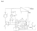
- a high pressure pump 1 is a fluid to be treated, usually Water in the form of seawater, seawater, brackish or sewage, to one or several reverse osmosis modules 2 promotes.
- a high pressure pump 1 is a fluid to be treated, usually Water in the form of seawater, seawater, brackish or sewage, to one or several reverse osmosis modules 2 promotes.
- high osmotic Pressure within these modules 2 enters the membranes arranged therein Separation effect on. Behind the membranes flows purified liquid, the so-called Permeate, with low pressure, is collected and used again fed.
- the high pressure is on low-pressure fluid, also called feed fluid, transmitted.
- This a line 8 removed food can be supplied in a variety of ways and is not limited to the illustrated embodiment.
- This fluid then enters at high pressure on the left side of the upper Pipe chamber 3.1 of the pressure exchanger and flows through check valves. 5 a booster pump 6, which is disposed within the piping system.
- the Check valves 5 prevent backflow of the now more energetic Fluid in the line 8.
- the booster pump 6 compensates only those low pressure drop in the osmotic process in the reverse osmosis modules 2 is created.
- the high-pressure pump 1 is therefore much smaller and thus more cost-effective, as in a system without Energy recovery.
- a fluid to be treated also called feed fluid
- two branch 9.1, 9.2 with non-return valves 5 through which a partial flow the fluid or feed fluid flows to the tube chambers 3.1, 3.2 of the pressure exchanger.
- this type of feeder is not mandatory. It can Other types of fluid supply to the pressure exchanger and the high-pressure pump 1 use find. Relevant is only that in the tube chambers 3.1, 3.2 leading lines 9.1 and 9.2 a form exists which is sufficient a fluid through the check valves 5 and a separating piston 4.1 or 4.2 from the tube chamber end on the side of the check valves 5 to the other tube chamber end to move on the side of the changeover 7.
- the tube chambers 3.1, 3.2 are provided with a plurality of sensors 14 and 15, wherein the sensors 14 on the one hand the position determination and on the other hand to determine the respective speed of the separating piston 4.1, 4.2 serve.
- the sensors 15 serve for detecting possible end positions of the separating pistons. All sensor signals will be fed into a control and regulating unit 16, which control signals to the servomotor 17 of the changeover 7, the controllable fittings 11, 12 respectively to a controllable fitting 11 and the controllable drive 13 of the booster pump. 6 supplies.
- the adjustable fittings 11, 12 can be used as a valve with actuator or be designed as a valve with positioner. They are types, with their help a precise sequence of circuits for the entire system through a Control unit 16 is possible.
- the separating piston 3.2 first reaches its reversal point at the end the tube chamber.
- the reaching of the turning point is from the sensor 14 to the Control unit 16 transmitted, whereupon from this a control signal to the Drive motor 17 of the changeover 7 is supplied.
- the changeover 7 switches and the pressures in the tube chambers 3.1 and 3.2 are exchanged.
- the separating piston 4.2 located in the end position reverses its direction of movement around and in the opposite direction to the check valves 5 accelerates so that at this time both separating piston 4.1, 4.2 supply a high pressure fluid in the direction of the booster pump 6.
- the time duration, in the two chambers 3.1, 3.2 and their separating piston a high pressure fluid in the direction supply the booster pump 6, is in the second range, before the separating piston 4.1 the tube chamber 3.1 reaches its reversal point.
- Further sensors 15 are arranged at the ends of each tube chamber and ensure a signal transmission to the control unit 16, if reason of changed operating conditions, a separating piston such a final or even Dead center should reach.
- the sensors 15 provide an alarm signal, with whose assistance the control unit 16 by actuating signals to the controllable Fittings or to the drive of the booster pump and / or the drive of the changeover valve 7 a new synchronization of the movement sequence of the separating piston starts.
- the readjustment of the Fluid velocity in a tube chamber referred to when in the other tube chamber a speed change has taken place. This synchronization effect also occurs when only the pressure exchanger is regulated. In this case follows the booster pump over its throttle curve.
- both the respective reversal points, and the Speeds of separating piston 4.1, 4.2 for each pressure exchange cycle one Pressure exchanger measured so that each operating condition is determined by the Change in piston speed. This applies both to a start-up operation and also for a shutdown operation of a equipped with such a pressure exchanger Investment.
- control unit 16 With the help of the drive motor 17 to the changeover 7 results in the essential Advantage that the control unit 16 of switching cycle to switching cycle and even react immediately during a switching cycle.
- control unit 16 the operation and the Synchronization of several pressure exchangers in parallel or in series can reliably regulate.
- the constant speed measurement of the Flow in the tube chambers 3.1, 3.2 of the pressure exchanger provides the other Advantage that this data with the help of an interface directly to the booster pump System be forwarded, if this via a speed-controlled drive 13th features.
- the booster pump has only one fixed-speed drive, then behind the booster pump 6 can affect performance take place acting as a throttle valve controllable fitting.
Landscapes
- Engineering & Computer Science (AREA)
- Chemical & Material Sciences (AREA)
- Water Supply & Treatment (AREA)
- Mechanical Engineering (AREA)
- General Engineering & Computer Science (AREA)
- Nanotechnology (AREA)
- Chemical Kinetics & Catalysis (AREA)
- Separation Using Semi-Permeable Membranes (AREA)
- Separation By Low-Temperature Treatments (AREA)
Abstract
Description
- Fig. 1
- ein Diagramm und die
- Fig. 2
- ein Schaltschema einer Anlage
- A =
- Fläche, in m2
- ADF =
- Durchflußfläche, in m2
- F =
- Kraft, in N
- p =
- Druck, in bar
- I =
- Impuls, in kgm/s
- ΔI =
- Impulsänderung, in kgm/s
- m =
- Masse, in kg
- w =
- Bewegungsgeschwindigkeit des Umschaltorgans, in °/s oder m/s
- Δt =
- Zeitänderung, in s
- vFluid =
- Fluidgeschwindigkeit in einer Rohrkammer, in m/s
Claims (20)
- Drucktauschersystem mit mindestens zwei Rohrkammern, wobei mehrere Umschaltarmaturen die Strömungswege von Flüssigkeitsströmen durch die mindestens zwei Rohrkammern umsteuern, und mindestens eine angetriebene Umschaltarmatur die Strömungswege zwischen einer ein energiereiches Hochdruckfluid bereitstellenden Lieferquelle und den Rohrkammern wechselweise umsteuert, dadurch gekennzeichnet, dass in der Umschaltarmatur das angetriebene Umschaltorgan bei der Umsteuerung der Richtung der Flüssigkeitsströme und beim Absperren von vorher geöffneten Strömungswegen einen variablen und/oder diskontinuierlicher Bewegungsablauf aufweist.
- Drucktauschersystem nach Anspruch 1, dadurch gekennzeichnet, dass beim Absperren einer aufgefüllten Rohrkammer das angetriebene Umschaltorgan eine reduzierte Bewegungsgeschwindigkeit (w) aufweist.
- Drucktauschersystem nach Anspruch 1 oder 2, dadurch gekennzeichnet, dass eine Reduzierung der Bewegungsgeschwindigkeit (w) des angetriebenen Umschaltorgans unmittelbar vor einem Verschluß einer Rohrkammer erfolgt.
- Drucktauschersystem nach Anspruch 1, 2 oder 3, dadurch gekennzeichnet, dass die Reduzierung der Bewegungsgeschwindigkeit (w) im Bereich von einigen Millisekunden bis zu einigen Sekunden liegt.
- Drucktauschersystem nach einem der Ansprüche 1 bis 4, dadurch gekennzeichnet, dass nach der Absperrung einer mit Niederdruck aufgefüllten Rohrkammer das angetriebene Umschaltorgan einen Haltepunkt einnimmt.
- Drucktauschersystem nach Anspruch 5, dadurch gekennzeichnet, dass im Haltepunkt für eine Verweildauer im Bereich von einigen Millisekunden bis zu einigen Sekunden die Bewegungsgeschwindigkeit (w) des angetriebenen Umschaltorgans auf Null reduziert ist.
- Drucktauschersystem nach einem der Ansprüche 1 bis 6, dadurch gekennzeichnet, dass nach der Verweildauer des angetriebenen Umschaltorgans im Haltepunkt eine Beschleunigung auf die normale Bewegungsgeschwindigkeit (w) erfolgt.
- Drucktauschersystem nach einem der Ansprüche 1 bis 7, dadurch gekennzeichnet, dass ein Antriebsmotor des Umschaltorgans veränderbare Drehzahlen und/oder Hubbewegungen aufweist.
- Drucktauschersystem nach Anspruch 8, dadurch gekennzeichnet, dass der Antriebsmotor als Servomotor elektrischer, hydraulischer oder hydropneumatischer Bauart ausgebildet ist.
- Drucktauschersystem nach den Ansprüchen 8 und 9, dadurch gekennzeichnet, dass der Antriebsmotor mit einer die Geschwindigkeit und/oder Dynamik beeinflussenden Regeleinrichtung verbunden ist.
- Drucktauschersystem nach einem der Ansprüche 1 bis 10, dadurch gekennzeichnet, dass die Rohrkammern (3.1, 3.2) mit mehreren, Position und Bewegung der Trennkolben (4.1, 4.2) erfassenden Sensoren (14, 15) versehen sind.
- Drucktauschersystem nach einem der Ansprüche 1 bis 11, dadurch gekennzeichnet, dass einer Boosterpumpe (6) und einer Umschaltarmatur (7) regelbare Armaturen (11, 12) nachgeordnet sind.
- Drucktauschersystem nach einem der Ansprüche 1 bis 11, dadurch gekennzeichnet, dass die Boosterpumpe (6) und/oder die Umschaltarmatur (7) mit einem regelbaren Antrieb (13, 17) verbunden sind.
- Drucktauschersystem nach einem der Ansprüche 1 bis 13, dadurch gekennzeichnet, dass die Sensoren (14, 15), die regelbare Armaturen (11, 12) und die regelbaren Antriebe (13, 17) mit einer Steuer- und Regeleinheit (16) verbunden sind.
- Drucktauschersystem nach einem der Ansprüche 1 bis 14, dadurch gekennzeichnet, dass die Steuer- und Regeleinheit (16) mittels Sensorsignale die Bewegungsabläufe der Fluidströme in den Rohrkammern (3.1, 3.2) und/oder der Trennkolben (4.1, 4.2) überwacht und bei Abweichungen von vorgegebenen Abläufen durch Übermittlung von Stellsignalen an die regelbaren Armaturen (11, 12) und/oder die regelbaren Antriebe (13, 17) deren Funktion und die Abläufe im Drucktauscher verändert.
- Drucktauschersystem nach Anspruch 15, dadurch gekennzeichnet, dass die Steuer- und Regeleinheit (16) eine Synchronisation des Drucktauschers steuert und regelt.
- Drucktauschersystem nach einem der Ansprüche 1 bis 8, dadurch gekennzeichnet, dass in den Rohrkammern an sich bekannte, stofflich ausgebildete Trennkörper angeordnet sind.
- Drucktauschersystem nach einem der Ansprüche 1 bis 12, dadurch gekennzeichnet, dass die Umschaltarmatur mit einem oder mehreren, rotierend angetriebenen Umschaltorganen versehen ist.
- Drucktauschersystem nach einem der Ansprüche 1 bis 12, dadurch gekennzeichnet, dass die Umschaltarmatur mit einem oder mehreren, reversierend linear angetriebenen Umschaltorganen versehen ist.
- Drucktauschersystem nach einem der Ansprüche 1 bis 14, dadurch gekennzeichnet, dass das Umschaltorgan eine Kombinationsbewegung aus Dreh- und Hubbewegung ausführt.
Applications Claiming Priority (4)
| Application Number | Priority Date | Filing Date | Title |
|---|---|---|---|
| DE10359332 | 2003-12-17 | ||
| DE10359332 | 2003-12-17 | ||
| DE102004029231 | 2004-06-17 | ||
| DE102004029231A DE102004029231A1 (de) | 2003-12-17 | 2004-06-17 | Drucktauschersystem |
Publications (2)
| Publication Number | Publication Date |
|---|---|
| EP1547670A1 true EP1547670A1 (de) | 2005-06-29 |
| EP1547670B1 EP1547670B1 (de) | 2007-09-26 |
Family
ID=34553334
Family Applications (1)
| Application Number | Title | Priority Date | Filing Date |
|---|---|---|---|
| EP20040023544 Expired - Lifetime EP1547670B1 (de) | 2003-12-17 | 2004-10-02 | Drucktauschersystem |
Country Status (7)
| Country | Link |
|---|---|
| US (1) | US7168927B2 (de) |
| EP (1) | EP1547670B1 (de) |
| JP (1) | JP2005177753A (de) |
| AT (1) | ATE374071T1 (de) |
| DE (1) | DE502004005072D1 (de) |
| DK (1) | DK1547670T3 (de) |
| ES (1) | ES2293143T3 (de) |
Cited By (8)
| Publication number | Priority date | Publication date | Assignee | Title |
|---|---|---|---|---|
| WO2010022726A1 (de) * | 2008-08-29 | 2010-03-04 | Danfoss A/S | Umkehrosmosevorrichtung |
| WO2011045628A1 (en) * | 2009-10-16 | 2011-04-21 | Arne Fritdjof Myran | Optimized work exchanger system |
| CN101456607B (zh) * | 2008-11-13 | 2011-06-29 | 杭州水处理技术研究开发中心有限公司 | 一种水压驱动的切换阀组 |
| WO2011103875A3 (en) * | 2010-02-26 | 2011-11-17 | Danfoss A/S | Reverse osmosis system |
| CN104591419A (zh) * | 2015-01-07 | 2015-05-06 | 成都邦研科技有限公司 | 一种血液透析用制水设备单级恒压供水装置 |
| US9044402B2 (en) | 2012-07-06 | 2015-06-02 | Egalet Ltd. | Abuse-deterrent pharmaceutical compositions for controlled release |
| CN114352597A (zh) * | 2022-01-25 | 2022-04-15 | 佳木斯大学 | 一种过载反向冲击阀及防止过载的方法 |
| CN116838563A (zh) * | 2022-03-25 | 2023-10-03 | 中国石油化工股份有限公司 | 高压加氢装置及其功能交换器 |
Families Citing this family (31)
| Publication number | Priority date | Publication date | Assignee | Title |
|---|---|---|---|---|
| WO2004080576A1 (de) * | 2003-03-12 | 2004-09-23 | Ksb Aktiengesellschaft | Armatur für anlagen mit drucktauschern |
| CN100390074C (zh) * | 2006-03-06 | 2008-05-28 | 天津大学 | 反渗透海水淡化能量回收装置多通道压力切换器 |
| US7988428B1 (en) | 2006-09-21 | 2011-08-02 | Macharg John P | Axial piston machine |
| US20080185045A1 (en) * | 2007-02-05 | 2008-08-07 | General Electric Company | Energy recovery apparatus and method |
| JP4870648B2 (ja) * | 2007-10-25 | 2012-02-08 | 株式会社荏原製作所 | 動力回収システム |
| US7799221B1 (en) | 2008-01-15 | 2010-09-21 | Macharg John P | Combined axial piston liquid pump and energy recovery pressure exchanger |
| JP5081693B2 (ja) * | 2008-03-31 | 2012-11-28 | 株式会社荏原製作所 | 動力回収チャンバー |
| WO2010004543A1 (en) * | 2008-07-09 | 2010-01-14 | I.D.E. Technologies | Method of improving performance of a reverse osmosis system for seawater desalination, and modified reverse osmosis system obtained thereby |
| JP4865833B2 (ja) * | 2009-04-30 | 2012-02-01 | 三菱重工業株式会社 | 圧力変換器用の管体 |
| CN103537190B (zh) | 2009-05-15 | 2016-06-29 | 株式会社荏原制作所 | 海水淡化系统及能量交换腔室 |
| WO2010149169A2 (en) | 2009-06-24 | 2010-12-29 | Egalet A/S | Controlled release formulations |
| US9644761B2 (en) | 2011-09-30 | 2017-05-09 | General Electric Company | Desalination system with energy recovery and related pumps, valves and controller |
| US9387440B2 (en) | 2011-09-30 | 2016-07-12 | General Electric Company | Desalination system with energy recovery and related pumps, valves and controller |
| JP5665195B2 (ja) * | 2011-12-05 | 2015-02-04 | 株式会社電業社機械製作所 | エネルギー回収装置 |
| US9897080B2 (en) | 2012-12-04 | 2018-02-20 | General Electric Company | Rotary control valve for reverse osmosis feed water pump with energy recovery |
| US9638179B2 (en) | 2012-12-04 | 2017-05-02 | General Electric Company | Hydraulic control system for a reverse osmosis hydraulic pump |
| GB2508904A (en) * | 2012-12-14 | 2014-06-18 | Ide Technologies Ltd | Reverse osmosis system control |
| SG10201707727UA (en) | 2012-12-21 | 2017-10-30 | Porifera Inc | Separation systems, elements, and methods for separation utilizing stacked membranes and spacers |
| JP6010466B2 (ja) * | 2013-01-16 | 2016-10-19 | 株式会社荏原製作所 | 海水淡水化システムおよびエネルギー回収装置 |
| US10500544B2 (en) | 2013-03-15 | 2019-12-10 | Porifera, Inc. | Advancements in osmotically driven membrane systems including multi-stage purification |
| DK3052814T3 (da) * | 2013-10-03 | 2020-06-08 | Energy Recovery Inc | Fraktureringssystem med hydraulisk energioverførselssystem |
| US9874216B2 (en) * | 2013-12-20 | 2018-01-23 | General Electric Company | Thrust bearings for centrifugal pumps |
| JP6057348B2 (ja) * | 2014-07-17 | 2017-01-11 | 株式会社電業社機械製作所 | エネルギー回収装置 |
| US10953368B2 (en) * | 2015-01-27 | 2021-03-23 | Nanyang Technological University | Integrated reverse osmosis module with energy recovery for desalination |
| WO2016210337A2 (en) | 2015-06-24 | 2016-12-29 | Porifera, Inc. | Methods of dewatering of alcoholic solutions via forward osmosis and related systems |
| WO2018119460A1 (en) | 2016-12-23 | 2018-06-28 | Porifera, Inc. | Removing components of alcoholic solutions via forward osmosis and related systems |
| US10920555B2 (en) * | 2018-11-09 | 2021-02-16 | Flowserve Management Company | Fluid exchange devices and related controls, systems, and methods |
| WO2020097565A1 (en) | 2018-11-09 | 2020-05-14 | Flowserve Management Company | Pistons for use in fluid exchange devices and related devices, systems, and methods |
| US12092136B2 (en) | 2018-11-09 | 2024-09-17 | Flowserve Pte. Ltd. | Fluid exchange devices and related controls, systems, and methods |
| MX2022005109A (es) | 2019-12-12 | 2022-05-30 | Flowserve Man Co | Dispositivos de intercambio de fluidos y controles, sistemas y metodos relacionados. |
| ES2848924B2 (es) | 2021-06-04 | 2022-03-29 | Latorre Carrion Manuel | Dispositivo de intercambio de presion de sentido unico para plantas desaladoras por osmosis inversa |
Citations (5)
| Publication number | Priority date | Publication date | Assignee | Title |
|---|---|---|---|---|
| FR2568321A1 (fr) * | 1984-07-30 | 1986-01-31 | Eszakdunantuli Viz Es Csatorna | Procede et installation d'exploitation de l'energie potentielle d'un liquide |
| GB2204664A (en) * | 1986-05-15 | 1988-11-16 | Oceanic Systems Limited | Spool valves |
| US5306428A (en) * | 1992-10-29 | 1994-04-26 | Tonner John B | Method of recovering energy from reverse osmosis waste streams |
| DE10057613A1 (de) * | 2000-11-21 | 2002-05-29 | Aloys Wobben | Verfahren und Vorrichtung zum Entsalzen von Wasser |
| JP2003144856A (ja) * | 2001-11-12 | 2003-05-20 | Sasakura Engineering Co Ltd | 逆浸透膜装置用エネルギー回収装置 |
Family Cites Families (9)
| Publication number | Priority date | Publication date | Assignee | Title |
|---|---|---|---|---|
| US3431747A (en) * | 1966-12-01 | 1969-03-11 | Hadi T Hashemi | Engine for exchanging energy between high and low pressure systems |
| US4637783A (en) * | 1980-10-20 | 1987-01-20 | Sri International | Fluid motor-pumping apparatus and method for energy recovery |
| JPS58195192U (ja) * | 1982-06-23 | 1983-12-26 | 株式会社明電舎 | ウオ−タハンマ防止制御装置 |
| JPS61270571A (ja) * | 1985-05-22 | 1986-11-29 | Matsushita Electric Ind Co Ltd | モ−タ駆動水弁 |
| US5132172A (en) * | 1986-06-11 | 1992-07-21 | Minnesota Mining And Manufacturing Company | Primed polyolefin surfaces for epoxy adhesives |
| JPH05270070A (ja) * | 1992-03-26 | 1993-10-19 | Toshiba Corp | 画像形成装置 |
| US5797429A (en) * | 1996-03-11 | 1998-08-25 | Desalco, Ltd. | Linear spool valve device for work exchanger system |
| US6017200A (en) * | 1997-08-12 | 2000-01-25 | Science Applications International Corporation | Integrated pumping and/or energy recovery system |
| US6537035B2 (en) * | 2001-04-10 | 2003-03-25 | Scott Shumway | Pressure exchange apparatus |
-
2004
- 2004-10-02 AT AT04023544T patent/ATE374071T1/de not_active IP Right Cessation
- 2004-10-02 DE DE200450005072 patent/DE502004005072D1/de not_active Expired - Lifetime
- 2004-10-02 EP EP20040023544 patent/EP1547670B1/de not_active Expired - Lifetime
- 2004-10-02 ES ES04023544T patent/ES2293143T3/es not_active Expired - Lifetime
- 2004-10-02 DK DK04023544T patent/DK1547670T3/da active
- 2004-12-17 JP JP2004365626A patent/JP2005177753A/ja active Pending
- 2004-12-17 US US11/013,321 patent/US7168927B2/en not_active Expired - Fee Related
Patent Citations (5)
| Publication number | Priority date | Publication date | Assignee | Title |
|---|---|---|---|---|
| FR2568321A1 (fr) * | 1984-07-30 | 1986-01-31 | Eszakdunantuli Viz Es Csatorna | Procede et installation d'exploitation de l'energie potentielle d'un liquide |
| GB2204664A (en) * | 1986-05-15 | 1988-11-16 | Oceanic Systems Limited | Spool valves |
| US5306428A (en) * | 1992-10-29 | 1994-04-26 | Tonner John B | Method of recovering energy from reverse osmosis waste streams |
| DE10057613A1 (de) * | 2000-11-21 | 2002-05-29 | Aloys Wobben | Verfahren und Vorrichtung zum Entsalzen von Wasser |
| JP2003144856A (ja) * | 2001-11-12 | 2003-05-20 | Sasakura Engineering Co Ltd | 逆浸透膜装置用エネルギー回収装置 |
Non-Patent Citations (1)
| Title |
|---|
| PATENT ABSTRACTS OF JAPAN vol. 2003, no. 09 3 September 2003 (2003-09-03) * |
Cited By (13)
| Publication number | Priority date | Publication date | Assignee | Title |
|---|---|---|---|---|
| US9416795B2 (en) | 2008-08-29 | 2016-08-16 | Danfoss A/S | Reverse osmosis system |
| CN102138007A (zh) * | 2008-08-29 | 2011-07-27 | 丹佛斯公司 | 反渗透设备 |
| WO2010022726A1 (de) * | 2008-08-29 | 2010-03-04 | Danfoss A/S | Umkehrosmosevorrichtung |
| CN102138007B (zh) * | 2008-08-29 | 2014-04-23 | 丹佛斯公司 | 反渗透设备 |
| CN101456607B (zh) * | 2008-11-13 | 2011-06-29 | 杭州水处理技术研究开发中心有限公司 | 一种水压驱动的切换阀组 |
| WO2011045628A1 (en) * | 2009-10-16 | 2011-04-21 | Arne Fritdjof Myran | Optimized work exchanger system |
| US9821273B2 (en) | 2010-02-26 | 2017-11-21 | Danfoss A/S | Reverse osmosis system |
| WO2011103875A3 (en) * | 2010-02-26 | 2011-11-17 | Danfoss A/S | Reverse osmosis system |
| US9044402B2 (en) | 2012-07-06 | 2015-06-02 | Egalet Ltd. | Abuse-deterrent pharmaceutical compositions for controlled release |
| CN104591419A (zh) * | 2015-01-07 | 2015-05-06 | 成都邦研科技有限公司 | 一种血液透析用制水设备单级恒压供水装置 |
| CN114352597A (zh) * | 2022-01-25 | 2022-04-15 | 佳木斯大学 | 一种过载反向冲击阀及防止过载的方法 |
| CN114352597B (zh) * | 2022-01-25 | 2024-04-23 | 佳木斯大学 | 一种过载反向冲击阀及防止过载的方法 |
| CN116838563A (zh) * | 2022-03-25 | 2023-10-03 | 中国石油化工股份有限公司 | 高压加氢装置及其功能交换器 |
Also Published As
| Publication number | Publication date |
|---|---|
| ES2293143T3 (es) | 2008-03-16 |
| DK1547670T3 (da) | 2008-01-07 |
| ATE374071T1 (de) | 2007-10-15 |
| DE502004005072D1 (de) | 2007-11-08 |
| US7168927B2 (en) | 2007-01-30 |
| JP2005177753A (ja) | 2005-07-07 |
| US20050166978A1 (en) | 2005-08-04 |
| EP1547670B1 (de) | 2007-09-26 |
Similar Documents
| Publication | Publication Date | Title |
|---|---|---|
| EP1547670B1 (de) | Drucktauschersystem | |
| DE2609434C2 (de) | Einrichtung zur Steuerung eines hydraulischen Motors | |
| WO2011113510A1 (de) | Antrieb mit notschliessfunktion | |
| DE1576088B2 (de) | Schnellentlastungsventil fuer hydraulische kraftzylinder | |
| DE2654366A1 (de) | Hydroventileinrichtung | |
| DE2512480C3 (de) | Ventilvorrichtung für einen hydraulisch betätigbaren elektrischen Leistungsschalter | |
| EP1339480B1 (de) | Verfahren und vorrichtung zum entsalzen von wasser | |
| DE102009020932A1 (de) | Druckaustauscher mit Linearantrieb | |
| DE4236460C2 (de) | Drucksteuer- und/oder Regelvorrichtung für ein fluidisches Medium, insbesondere Luft oder Gas | |
| EP1204460A1 (de) | Verfahren und vorrichtung zum entsalzen von wasser | |
| EP0055981A1 (de) | Wasserentsalzungssystem nach dem Verfahren der umgekehrten Osmose | |
| DE3434014A1 (de) | Hydraulische steuerung | |
| DE102004029231A1 (de) | Drucktauschersystem | |
| DE2336512C2 (de) | Ventil | |
| DE3222672C1 (de) | Einrichtung zum Verstellen von Schubumkehrern | |
| DE2218472A1 (de) | Hydrostatisches getriebe | |
| DE4235698C2 (de) | Hydrostatisches Antriebssystem | |
| DE1090480B (de) | Steuereinrichtung fuer vorzugsweise mehrere von einer Pumpe versorgte hydraulische Antriebe | |
| DE69016006T2 (de) | Hydraulische Maschine mit dem Vermögen des gleichzeitigen Entspannens einer Flüssigkeit und Verdichtens einer anderen Flüssigkeit. | |
| DE4402093A1 (de) | Hydrostatisches Antriebssystem | |
| DE2855162C3 (de) | Prüfeinrichtung für Beschleunigungssensoren | |
| DE3418261A1 (de) | Ventilanordnung zur steuerung und ueberwachung des arbeitsdruckes eines hydraulischen verbrauchers | |
| DE4311277C2 (de) | Rohraufgeber, bsw. Dreikammer-Rohraufgeber | |
| DE10057613C2 (de) | Verfahren und Vorrichtung zum Entsalzen von Wasser | |
| DE2856805C3 (de) | Vorrichtung zum Regeln der Kraftstoffzufuhr zu einer eine Pumpe einer hydraulischen Anlage antreibenden Brennkraftmaschine |
Legal Events
| Date | Code | Title | Description |
|---|---|---|---|
| PUAI | Public reference made under article 153(3) epc to a published international application that has entered the european phase |
Free format text: ORIGINAL CODE: 0009012 |
|
| AK | Designated contracting states |
Kind code of ref document: A1 Designated state(s): AT BE BG CH CY CZ DE DK EE ES FI FR GB GR HU IE IT LI LU MC NL PL PT RO SE SI SK TR |
|
| AX | Request for extension of the european patent |
Extension state: AL HR LT LV MK |
|
| 17P | Request for examination filed |
Effective date: 20051216 |
|
| AKX | Designation fees paid |
Designated state(s): AT BE BG CH CY CZ DE DK EE ES FI FR GB GR HU IE IT LI LU MC NL PL PT RO SE SI SK TR |
|
| 17Q | First examination report despatched |
Effective date: 20060201 |
|
| 17Q | First examination report despatched |
Effective date: 20060201 |
|
| GRAP | Despatch of communication of intention to grant a patent |
Free format text: ORIGINAL CODE: EPIDOSNIGR1 |
|
| GRAS | Grant fee paid |
Free format text: ORIGINAL CODE: EPIDOSNIGR3 |
|
| GRAA | (expected) grant |
Free format text: ORIGINAL CODE: 0009210 |
|
| AK | Designated contracting states |
Kind code of ref document: B1 Designated state(s): AT BE BG CH CY CZ DE DK EE ES FI FR GB GR HU IE IT LI LU MC NL PL PT RO SE SI SK TR |
|
| REG | Reference to a national code |
Ref country code: GB Ref legal event code: FG4D Free format text: NOT ENGLISH |
|
| REG | Reference to a national code |
Ref country code: CH Ref legal event code: EP |
|
| REF | Corresponds to: |
Ref document number: 502004005072 Country of ref document: DE Date of ref document: 20071108 Kind code of ref document: P |
|
| REG | Reference to a national code |
Ref country code: IE Ref legal event code: FG4D Free format text: LANGUAGE OF EP DOCUMENT: GERMAN |
|
| REG | Reference to a national code |
Ref country code: DK Ref legal event code: T3 |
|
| GBT | Gb: translation of ep patent filed (gb section 77(6)(a)/1977) |
Effective date: 20080109 |
|
| PG25 | Lapsed in a contracting state [announced via postgrant information from national office to epo] |
Ref country code: FI Free format text: LAPSE BECAUSE OF FAILURE TO SUBMIT A TRANSLATION OF THE DESCRIPTION OR TO PAY THE FEE WITHIN THE PRESCRIBED TIME-LIMIT Effective date: 20070926 |
|
| PG25 | Lapsed in a contracting state [announced via postgrant information from national office to epo] |
Ref country code: PL Free format text: LAPSE BECAUSE OF FAILURE TO SUBMIT A TRANSLATION OF THE DESCRIPTION OR TO PAY THE FEE WITHIN THE PRESCRIBED TIME-LIMIT Effective date: 20070926 |
|
| NLV1 | Nl: lapsed or annulled due to failure to fulfill the requirements of art. 29p and 29m of the patents act | ||
| REG | Reference to a national code |
Ref country code: ES Ref legal event code: FG2A Ref document number: 2293143 Country of ref document: ES Kind code of ref document: T3 |
|
| BERE | Be: lapsed |
Owner name: KSB A.G. Effective date: 20071031 |
|
| PG25 | Lapsed in a contracting state [announced via postgrant information from national office to epo] |
Ref country code: GR Free format text: LAPSE BECAUSE OF FAILURE TO SUBMIT A TRANSLATION OF THE DESCRIPTION OR TO PAY THE FEE WITHIN THE PRESCRIBED TIME-LIMIT Effective date: 20071227 Ref country code: NL Free format text: LAPSE BECAUSE OF FAILURE TO SUBMIT A TRANSLATION OF THE DESCRIPTION OR TO PAY THE FEE WITHIN THE PRESCRIBED TIME-LIMIT Effective date: 20070926 |
|
| REG | Reference to a national code |
Ref country code: IE Ref legal event code: FD4D |
|
| ET | Fr: translation filed | ||
| PG25 | Lapsed in a contracting state [announced via postgrant information from national office to epo] |
Ref country code: SK Free format text: LAPSE BECAUSE OF FAILURE TO SUBMIT A TRANSLATION OF THE DESCRIPTION OR TO PAY THE FEE WITHIN THE PRESCRIBED TIME-LIMIT Effective date: 20070926 Ref country code: PT Free format text: LAPSE BECAUSE OF FAILURE TO SUBMIT A TRANSLATION OF THE DESCRIPTION OR TO PAY THE FEE WITHIN THE PRESCRIBED TIME-LIMIT Effective date: 20080226 Ref country code: CZ Free format text: LAPSE BECAUSE OF FAILURE TO SUBMIT A TRANSLATION OF THE DESCRIPTION OR TO PAY THE FEE WITHIN THE PRESCRIBED TIME-LIMIT Effective date: 20070926 Ref country code: MC Free format text: LAPSE BECAUSE OF NON-PAYMENT OF DUE FEES Effective date: 20071031 |
|
| PG25 | Lapsed in a contracting state [announced via postgrant information from national office to epo] |
Ref country code: RO Free format text: LAPSE BECAUSE OF FAILURE TO SUBMIT A TRANSLATION OF THE DESCRIPTION OR TO PAY THE FEE WITHIN THE PRESCRIBED TIME-LIMIT Effective date: 20070926 Ref country code: SE Free format text: LAPSE BECAUSE OF FAILURE TO SUBMIT A TRANSLATION OF THE DESCRIPTION OR TO PAY THE FEE WITHIN THE PRESCRIBED TIME-LIMIT Effective date: 20071226 |
|
| PLBE | No opposition filed within time limit |
Free format text: ORIGINAL CODE: 0009261 |
|
| STAA | Information on the status of an ep patent application or granted ep patent |
Free format text: STATUS: NO OPPOSITION FILED WITHIN TIME LIMIT |
|
| 26N | No opposition filed |
Effective date: 20080627 |
|
| PG25 | Lapsed in a contracting state [announced via postgrant information from national office to epo] |
Ref country code: BE Free format text: LAPSE BECAUSE OF NON-PAYMENT OF DUE FEES Effective date: 20071031 |
|
| PG25 | Lapsed in a contracting state [announced via postgrant information from national office to epo] |
Ref country code: IE Free format text: LAPSE BECAUSE OF FAILURE TO SUBMIT A TRANSLATION OF THE DESCRIPTION OR TO PAY THE FEE WITHIN THE PRESCRIBED TIME-LIMIT Effective date: 20070926 |
|
| PG25 | Lapsed in a contracting state [announced via postgrant information from national office to epo] |
Ref country code: EE Free format text: LAPSE BECAUSE OF FAILURE TO SUBMIT A TRANSLATION OF THE DESCRIPTION OR TO PAY THE FEE WITHIN THE PRESCRIBED TIME-LIMIT Effective date: 20070926 |
|
| PG25 | Lapsed in a contracting state [announced via postgrant information from national office to epo] |
Ref country code: AT Free format text: LAPSE BECAUSE OF NON-PAYMENT OF DUE FEES Effective date: 20071002 |
|
| PG25 | Lapsed in a contracting state [announced via postgrant information from national office to epo] |
Ref country code: SI Free format text: LAPSE BECAUSE OF FAILURE TO SUBMIT A TRANSLATION OF THE DESCRIPTION OR TO PAY THE FEE WITHIN THE PRESCRIBED TIME-LIMIT Effective date: 20070926 |
|
| PG25 | Lapsed in a contracting state [announced via postgrant information from national office to epo] |
Ref country code: CY Free format text: LAPSE BECAUSE OF FAILURE TO SUBMIT A TRANSLATION OF THE DESCRIPTION OR TO PAY THE FEE WITHIN THE PRESCRIBED TIME-LIMIT Effective date: 20070926 |
|
| PG25 | Lapsed in a contracting state [announced via postgrant information from national office to epo] |
Ref country code: BG Free format text: LAPSE BECAUSE OF FAILURE TO SUBMIT A TRANSLATION OF THE DESCRIPTION OR TO PAY THE FEE WITHIN THE PRESCRIBED TIME-LIMIT Effective date: 20071226 Ref country code: LU Free format text: LAPSE BECAUSE OF NON-PAYMENT OF DUE FEES Effective date: 20071002 |
|
| PG25 | Lapsed in a contracting state [announced via postgrant information from national office to epo] |
Ref country code: TR Free format text: LAPSE BECAUSE OF FAILURE TO SUBMIT A TRANSLATION OF THE DESCRIPTION OR TO PAY THE FEE WITHIN THE PRESCRIBED TIME-LIMIT Effective date: 20070926 Ref country code: HU Free format text: LAPSE BECAUSE OF FAILURE TO SUBMIT A TRANSLATION OF THE DESCRIPTION OR TO PAY THE FEE WITHIN THE PRESCRIBED TIME-LIMIT Effective date: 20080327 |
|
| REG | Reference to a national code |
Ref country code: FR Ref legal event code: PLFP Year of fee payment: 12 |
|
| PGFP | Annual fee paid to national office [announced via postgrant information from national office to epo] |
Ref country code: DK Payment date: 20151022 Year of fee payment: 12 |
|
| PGFP | Annual fee paid to national office [announced via postgrant information from national office to epo] |
Ref country code: IT Payment date: 20151030 Year of fee payment: 12 Ref country code: CH Payment date: 20151022 Year of fee payment: 12 Ref country code: GB Payment date: 20151022 Year of fee payment: 12 Ref country code: DE Payment date: 20151007 Year of fee payment: 12 |
|
| PGFP | Annual fee paid to national office [announced via postgrant information from national office to epo] |
Ref country code: ES Payment date: 20151013 Year of fee payment: 12 Ref country code: FR Payment date: 20151022 Year of fee payment: 12 |
|
| REG | Reference to a national code |
Ref country code: DE Ref legal event code: R119 Ref document number: 502004005072 Country of ref document: DE |
|
| REG | Reference to a national code |
Ref country code: DK Ref legal event code: EBP Effective date: 20161031 |
|
| REG | Reference to a national code |
Ref country code: CH Ref legal event code: PL |
|
| GBPC | Gb: european patent ceased through non-payment of renewal fee |
Effective date: 20161002 |
|
| REG | Reference to a national code |
Ref country code: FR Ref legal event code: ST Effective date: 20170630 |
|
| PG25 | Lapsed in a contracting state [announced via postgrant information from national office to epo] |
Ref country code: DE Free format text: LAPSE BECAUSE OF NON-PAYMENT OF DUE FEES Effective date: 20170503 Ref country code: FR Free format text: LAPSE BECAUSE OF NON-PAYMENT OF DUE FEES Effective date: 20161102 Ref country code: GB Free format text: LAPSE BECAUSE OF NON-PAYMENT OF DUE FEES Effective date: 20161002 Ref country code: LI Free format text: LAPSE BECAUSE OF NON-PAYMENT OF DUE FEES Effective date: 20161031 Ref country code: CH Free format text: LAPSE BECAUSE OF NON-PAYMENT OF DUE FEES Effective date: 20161031 |
|
| PG25 | Lapsed in a contracting state [announced via postgrant information from national office to epo] |
Ref country code: IT Free format text: LAPSE BECAUSE OF NON-PAYMENT OF DUE FEES Effective date: 20161002 |
|
| PG25 | Lapsed in a contracting state [announced via postgrant information from national office to epo] |
Ref country code: DK Free format text: LAPSE BECAUSE OF NON-PAYMENT OF DUE FEES Effective date: 20161031 |
|
| PG25 | Lapsed in a contracting state [announced via postgrant information from national office to epo] |
Ref country code: ES Free format text: LAPSE BECAUSE OF NON-PAYMENT OF DUE FEES Effective date: 20161003 |
|
| REG | Reference to a national code |
Ref country code: ES Ref legal event code: FD2A Effective date: 20181126 |