EP1545026B1 - Verfahren zur Übertragung variabler Bitraten und dieses verwendende Sender und Empfänger - Google Patents
Verfahren zur Übertragung variabler Bitraten und dieses verwendende Sender und Empfänger Download PDFInfo
- Publication number
- EP1545026B1 EP1545026B1 EP05075561A EP05075561A EP1545026B1 EP 1545026 B1 EP1545026 B1 EP 1545026B1 EP 05075561 A EP05075561 A EP 05075561A EP 05075561 A EP05075561 A EP 05075561A EP 1545026 B1 EP1545026 B1 EP 1545026B1
- Authority
- EP
- European Patent Office
- Prior art keywords
- data
- frame
- error detecting
- detecting code
- information data
- Prior art date
- Legal status (The legal status is an assumption and is not a legal conclusion. Google has not performed a legal analysis and makes no representation as to the accuracy of the status listed.)
- Expired - Lifetime
Links
Images


Classifications
-
- H—ELECTRICITY
- H04—ELECTRIC COMMUNICATION TECHNIQUE
- H04L—TRANSMISSION OF DIGITAL INFORMATION, e.g. TELEGRAPHIC COMMUNICATION
- H04L1/00—Arrangements for detecting or preventing errors in the information received
- H04L1/004—Arrangements for detecting or preventing errors in the information received by using forward error control
- H04L1/0045—Arrangements at the receiver end
- H04L1/0046—Code rate detection or code type detection
-
- H—ELECTRICITY
- H04—ELECTRIC COMMUNICATION TECHNIQUE
- H04B—TRANSMISSION
- H04B1/00—Details of transmission systems, not covered by a single one of groups H04B3/00 - H04B13/00; Details of transmission systems not characterised by the medium used for transmission
- H04B1/69—Spread spectrum techniques
- H04B1/707—Spread spectrum techniques using direct sequence modulation
-
- H—ELECTRICITY
- H04—ELECTRIC COMMUNICATION TECHNIQUE
- H04B—TRANSMISSION
- H04B7/00—Radio transmission systems, i.e. using radiation field
- H04B7/24—Radio transmission systems, i.e. using radiation field for communication between two or more posts
- H04B7/26—Radio transmission systems, i.e. using radiation field for communication between two or more posts at least one of which is mobile
- H04B7/2628—Radio transmission systems, i.e. using radiation field for communication between two or more posts at least one of which is mobile using code-division multiple access [CDMA] or spread spectrum multiple access [SSMA]
-
- H—ELECTRICITY
- H04—ELECTRIC COMMUNICATION TECHNIQUE
- H04J—MULTIPLEX COMMUNICATION
- H04J3/00—Time-division multiplex systems
- H04J3/02—Details
- H04J3/14—Monitoring arrangements
-
- H—ELECTRICITY
- H04—ELECTRIC COMMUNICATION TECHNIQUE
- H04J—MULTIPLEX COMMUNICATION
- H04J3/00—Time-division multiplex systems
- H04J3/16—Time-division multiplex systems in which the time allocation to individual channels within a transmission cycle is variable, e.g. to accommodate varying complexity of signals, to vary number of channels transmitted
- H04J3/1682—Allocation of channels according to the instantaneous demands of the users, e.g. concentrated multiplexers, statistical multiplexers
-
- H—ELECTRICITY
- H04—ELECTRIC COMMUNICATION TECHNIQUE
- H04L—TRANSMISSION OF DIGITAL INFORMATION, e.g. TELEGRAPHIC COMMUNICATION
- H04L1/00—Arrangements for detecting or preventing errors in the information received
- H04L1/0001—Systems modifying transmission characteristics according to link quality, e.g. power backoff
- H04L1/0002—Systems modifying transmission characteristics according to link quality, e.g. power backoff by adapting the transmission rate
-
- H—ELECTRICITY
- H04—ELECTRIC COMMUNICATION TECHNIQUE
- H04L—TRANSMISSION OF DIGITAL INFORMATION, e.g. TELEGRAPHIC COMMUNICATION
- H04L1/00—Arrangements for detecting or preventing errors in the information received
- H04L1/0001—Systems modifying transmission characteristics according to link quality, e.g. power backoff
- H04L1/0006—Systems modifying transmission characteristics according to link quality, e.g. power backoff by adapting the transmission format
- H04L1/0007—Systems modifying transmission characteristics according to link quality, e.g. power backoff by adapting the transmission format by modifying the frame length
-
- H—ELECTRICITY
- H04—ELECTRIC COMMUNICATION TECHNIQUE
- H04L—TRANSMISSION OF DIGITAL INFORMATION, e.g. TELEGRAPHIC COMMUNICATION
- H04L1/00—Arrangements for detecting or preventing errors in the information received
- H04L1/0001—Systems modifying transmission characteristics according to link quality, e.g. power backoff
- H04L1/0009—Systems modifying transmission characteristics according to link quality, e.g. power backoff by adapting the channel coding
- H04L1/0013—Rate matching, e.g. puncturing or repetition of code symbols
-
- H—ELECTRICITY
- H04—ELECTRIC COMMUNICATION TECHNIQUE
- H04L—TRANSMISSION OF DIGITAL INFORMATION, e.g. TELEGRAPHIC COMMUNICATION
- H04L1/00—Arrangements for detecting or preventing errors in the information received
- H04L1/0001—Systems modifying transmission characteristics according to link quality, e.g. power backoff
- H04L1/0036—Systems modifying transmission characteristics according to link quality, e.g. power backoff arrangements specific to the receiver
- H04L1/0038—Blind format detection
-
- H—ELECTRICITY
- H04—ELECTRIC COMMUNICATION TECHNIQUE
- H04L—TRANSMISSION OF DIGITAL INFORMATION, e.g. TELEGRAPHIC COMMUNICATION
- H04L1/00—Arrangements for detecting or preventing errors in the information received
- H04L1/0001—Systems modifying transmission characteristics according to link quality, e.g. power backoff
- H04L1/0036—Systems modifying transmission characteristics according to link quality, e.g. power backoff arrangements specific to the receiver
- H04L1/0039—Systems modifying transmission characteristics according to link quality, e.g. power backoff arrangements specific to the receiver other detection of signalling, e.g. detection of TFCI explicit signalling
-
- H—ELECTRICITY
- H04—ELECTRIC COMMUNICATION TECHNIQUE
- H04L—TRANSMISSION OF DIGITAL INFORMATION, e.g. TELEGRAPHIC COMMUNICATION
- H04L1/00—Arrangements for detecting or preventing errors in the information received
- H04L1/004—Arrangements for detecting or preventing errors in the information received by using forward error control
- H04L1/0056—Systems characterized by the type of code used
- H04L1/0061—Error detection codes
- H04L1/0063—Single parity check
-
- H—ELECTRICITY
- H04—ELECTRIC COMMUNICATION TECHNIQUE
- H04L—TRANSMISSION OF DIGITAL INFORMATION, e.g. TELEGRAPHIC COMMUNICATION
- H04L1/00—Arrangements for detecting or preventing errors in the information received
- H04L1/004—Arrangements for detecting or preventing errors in the information received by using forward error control
- H04L1/0056—Systems characterized by the type of code used
- H04L1/0071—Use of interleaving
-
- H—ELECTRICITY
- H04—ELECTRIC COMMUNICATION TECHNIQUE
- H04L—TRANSMISSION OF DIGITAL INFORMATION, e.g. TELEGRAPHIC COMMUNICATION
- H04L1/00—Arrangements for detecting or preventing errors in the information received
- H04L1/0078—Avoidance of errors by organising the transmitted data in a format specifically designed to deal with errors, e.g. location
- H04L1/0079—Formats for control data
-
- H—ELECTRICITY
- H04—ELECTRIC COMMUNICATION TECHNIQUE
- H04L—TRANSMISSION OF DIGITAL INFORMATION, e.g. TELEGRAPHIC COMMUNICATION
- H04L1/00—Arrangements for detecting or preventing errors in the information received
- H04L1/0078—Avoidance of errors by organising the transmitted data in a format specifically designed to deal with errors, e.g. location
- H04L1/0086—Unequal error protection
-
- H—ELECTRICITY
- H04—ELECTRIC COMMUNICATION TECHNIQUE
- H04L—TRANSMISSION OF DIGITAL INFORMATION, e.g. TELEGRAPHIC COMMUNICATION
- H04L1/00—Arrangements for detecting or preventing errors in the information received
- H04L1/08—Arrangements for detecting or preventing errors in the information received by repeating transmission, e.g. Verdan system
-
- H—ELECTRICITY
- H04—ELECTRIC COMMUNICATION TECHNIQUE
- H04L—TRANSMISSION OF DIGITAL INFORMATION, e.g. TELEGRAPHIC COMMUNICATION
- H04L7/00—Arrangements for synchronising receiver with transmitter
- H04L7/04—Speed or phase control by synchronisation signals
- H04L7/048—Speed or phase control by synchronisation signals using the properties of error detecting or error correcting codes, e.g. parity as synchronisation signal
-
- H—ELECTRICITY
- H04—ELECTRIC COMMUNICATION TECHNIQUE
- H04B—TRANSMISSION
- H04B2201/00—Indexing scheme relating to details of transmission systems not covered by a single group of H04B3/00 - H04B13/00
- H04B2201/69—Orthogonal indexing scheme relating to spread spectrum techniques in general
- H04B2201/707—Orthogonal indexing scheme relating to spread spectrum techniques in general relating to direct sequence modulation
- H04B2201/70703—Orthogonal indexing scheme relating to spread spectrum techniques in general relating to direct sequence modulation using multiple or variable rates
- H04B2201/70705—Rate detection
-
- H—ELECTRICITY
- H04—ELECTRIC COMMUNICATION TECHNIQUE
- H04L—TRANSMISSION OF DIGITAL INFORMATION, e.g. TELEGRAPHIC COMMUNICATION
- H04L1/00—Arrangements for detecting or preventing errors in the information received
- H04L1/0001—Systems modifying transmission characteristics according to link quality, e.g. power backoff
- H04L1/0009—Systems modifying transmission characteristics according to link quality, e.g. power backoff by adapting the channel coding
-
- H—ELECTRICITY
- H04—ELECTRIC COMMUNICATION TECHNIQUE
- H04L—TRANSMISSION OF DIGITAL INFORMATION, e.g. TELEGRAPHIC COMMUNICATION
- H04L1/00—Arrangements for detecting or preventing errors in the information received
- H04L1/0001—Systems modifying transmission characteristics according to link quality, e.g. power backoff
- H04L1/0023—Systems modifying transmission characteristics according to link quality, e.g. power backoff characterised by the signalling
- H04L1/0025—Transmission of mode-switching indication
-
- H—ELECTRICITY
- H04—ELECTRIC COMMUNICATION TECHNIQUE
- H04L—TRANSMISSION OF DIGITAL INFORMATION, e.g. TELEGRAPHIC COMMUNICATION
- H04L1/00—Arrangements for detecting or preventing errors in the information received
- H04L1/0001—Systems modifying transmission characteristics according to link quality, e.g. power backoff
- H04L1/0023—Systems modifying transmission characteristics according to link quality, e.g. power backoff characterised by the signalling
- H04L1/0032—Without explicit signalling
-
- H—ELECTRICITY
- H04—ELECTRIC COMMUNICATION TECHNIQUE
- H04L—TRANSMISSION OF DIGITAL INFORMATION, e.g. TELEGRAPHIC COMMUNICATION
- H04L1/00—Arrangements for detecting or preventing errors in the information received
- H04L1/004—Arrangements for detecting or preventing errors in the information received by using forward error control
- H04L1/0056—Systems characterized by the type of code used
- H04L1/0059—Convolutional codes
-
- H—ELECTRICITY
- H04—ELECTRIC COMMUNICATION TECHNIQUE
- H04L—TRANSMISSION OF DIGITAL INFORMATION, e.g. TELEGRAPHIC COMMUNICATION
- H04L1/00—Arrangements for detecting or preventing errors in the information received
- H04L2001/0098—Unequal error protection
-
- Y—GENERAL TAGGING OF NEW TECHNOLOGICAL DEVELOPMENTS; GENERAL TAGGING OF CROSS-SECTIONAL TECHNOLOGIES SPANNING OVER SEVERAL SECTIONS OF THE IPC; TECHNICAL SUBJECTS COVERED BY FORMER USPC CROSS-REFERENCE ART COLLECTIONS [XRACs] AND DIGESTS
- Y02—TECHNOLOGIES OR APPLICATIONS FOR MITIGATION OR ADAPTATION AGAINST CLIMATE CHANGE
- Y02D—CLIMATE CHANGE MITIGATION TECHNOLOGIES IN INFORMATION AND COMMUNICATION TECHNOLOGIES [ICT], I.E. INFORMATION AND COMMUNICATION TECHNOLOGIES AIMING AT THE REDUCTION OF THEIR OWN ENERGY USE
- Y02D30/00—Reducing energy consumption in communication networks
- Y02D30/50—Reducing energy consumption in communication networks in wire-line communication networks, e.g. low power modes or reduced link rate
-
- Y—GENERAL TAGGING OF NEW TECHNOLOGICAL DEVELOPMENTS; GENERAL TAGGING OF CROSS-SECTIONAL TECHNOLOGIES SPANNING OVER SEVERAL SECTIONS OF THE IPC; TECHNICAL SUBJECTS COVERED BY FORMER USPC CROSS-REFERENCE ART COLLECTIONS [XRACs] AND DIGESTS
- Y02—TECHNOLOGIES OR APPLICATIONS FOR MITIGATION OR ADAPTATION AGAINST CLIMATE CHANGE
- Y02D—CLIMATE CHANGE MITIGATION TECHNOLOGIES IN INFORMATION AND COMMUNICATION TECHNOLOGIES [ICT], I.E. INFORMATION AND COMMUNICATION TECHNOLOGIES AIMING AT THE REDUCTION OF THEIR OWN ENERGY USE
- Y02D30/00—Reducing energy consumption in communication networks
- Y02D30/70—Reducing energy consumption in communication networks in wireless communication networks
Definitions
- the present invention relates to a code division multiple access (CDMA) in mobile communications systems, and more particularly to a variable rate transmission method, a transmitter and receiver using the same method, which can realize apparent variable rate transmission by transmitting data contained in frames of a fixed length at a constant transmission rate.
- CDMA code division multiple access
- the information amount of a transmitted voice signal is not constant, but varies from time to time. Accordingly, the transmission rate can be changed by dividing the transmitted data into frames of a fixed duration, and by transmitting data of a variable bit length in each frame, thereby achieving effective transmission of information in each frame period. This can obviate useless transmission, thereby saving power consumption of the transmitter.
- the following method is taken to transmit data of a different transmission rate in the CDMA system.
- data whose transmission rate is lower than the frame transmission rate is transmitted using a part of transmission frames (see, for example, R. Padovani, "Reverse link performance of IS-95 based cellular systems", IEEE Personal Communications, vol.1, pp.28-34, 3rd Quarter 1994 ).
- data whose transmission rate is higher than the frame transmission rate is divided into a plurality of transmission channels, and the divided data are spread using different spreading codes to be transmitted.
- FEC Forward Error Correction
- the transmitting side transmits transmitted data (including the transmission rate information) which has undergone error correcting encoding
- the receiving side carries out the error correcting decoding followed by extraction of the transmission rate information to decide the effective data length in each received frame. Accordingly, the transmission rate information cannot be obtained until the end of the error correcting decoding.
- the decoding is performed before deciding the data length to be decoded, and hence the error correction cannot fully achieve its effect.
- the transmitted data includes data of various degrees of importance.
- TDMA Time Division Multiple Access
- RCR Physical digital cellular telecommunication system RCR standard, RCR STD-27
- Research & Development Center for Radio System This method, however, lacks flexibility to transmit various data of different transmission rates.
- high speed data is divided and spread to a plurality of signals using different spreading codes, and the spread signals are combined to be transmitted.
- the transmitting side must periodically inserts pilot symbols into transmitted data (see, for example, S. Sampei, "Fading Compensation for 16QAM in Land Mobile Communications", The Transactions of the Institute of Electronics, Information and Communication Engineers of Japan B-II, Vol. J72-B-II pp. 7-15, January 1989 , or its revised version, S. Sampei, et al. "Rayleigh Fading Compensation for QAM in Land Mobile Radio Communications", IEEE Transactions on Vehicular Technology, VOL. 42. No. 2, MAY 1993 ).
- This method will make it necessary for the plurality of transmission channels to send the same pilot symbols when the method is applied to the signals spread with the plurality of the spreading codes.
- the respective channels experience the same fading, and hence it is unnecessary to send the pilot symbols through the plurality of channels. Since multiple users share the same frequency band in CDMA, transmission of superfluous signals will reduce the number of users that can be accommodated in a limited frequency band because it will increase interference to other users by an amount corresponding to the transmission power necessary to send the superfluous signals.
- the high speed signal must be divided into a plurality of signals followed by spreading using different spreading codes and by combining of the spread signals, and the combined signal is converted into a radio frequency band followed by power amplification to be transmitted. If the plurality of spread signals are combined in the same phase, the amplitude of the combined signal will increase in proportion to the number of divided signals. This will require a high peak power liner transmission power amplifier. Such a power amplifier demanding large power consumption is unsuitable to portable telephones which require low power consumption.
- TIA/EIA Interim Standard "Mobile Station - Base Station Compatibility Standard for Dual Mode Wideband Spread Spectrum Cellular System” discloses a CDMA system in which variable length information is transmitted together with an error detecting code.
- the error detecting code may be positioned directly after the information data.
- WO 9501032 discloses a system for determining the rate at which data has been encoded in the receiver of a variable-rate communications System. Each frame of received symbols are decoded at each of the possible rates. Error metrics, which describe the quality of the decoded symbols for each frame decoded at each rate, are provided to a processor. The processor analyzes the error metrics using a decision process and determines the most probable rate at which the incoming symbols were encoded.
- Another object of the present invention is to provide a variable rate transmission method, a transmitter and a receiver, which can achieve data protection in accordance with the degree of importance of the data constituting in-the transmitted data.
- variable rate transmission method which varies an average transmission rate by transmitting each frame of a fixed duration, the frame holding transmitted data of a variable length, wherein a transmitting side comprising the steps of:
- the step of recovering the transmitted data may decide an end bit position of the transmitted data at a point preceding the point at which the error detecting code is detected by the number of bits of the error detecting code.
- the transmitting side may further comprise the steps of:
- the transmitting side may comprise the steps of:
- the transmitting side may comprise the steps of:
- the transmitting side may comprise the step of disposing the error detecting code at a fixed position in the each frame, and the receiving side comprises the steps of extracting the error detecting code placed at the fixed position in the each frame, and obtaining the number of bits of the transmitted data on the basis of the error detecting code.
- the method may be a CDMA data transmission method in which the transmitting side comprises the steps of performing primary modulation of the transmitted data and the error detecting code in the each frame, and performing secondary modulation of primary modulated data in each frame by using a spreading code sequence, to be transmitted.
- the transmitting side may comprise the step of performing error correcting encoding and interleaving of the transmitted data before the primary modulation, and wherein the receiving side comprises the steps of performing a primary demodulation of the transmitted data which is received, and performing deinterleaving and error correcting decoding of the transmitted data which have undergone the primary demodulation
- the transmitting side may comprise the step of:
- Transmission method may be a CDMA data transmission method in which the transmitting side comprises the steps of performing primary modulation of the transmitted data and the error detecting code in the each frame, and performing secondary modulation of primary modulated data in each frame by using a spreading code sequence, to be transmitted.
- the transmitting side may comprise the steps of:
- the transmitting side may comprise the step of:
- the transmitter may further comprise:
- the transmitter may further comprise:
- the transmitter may further comprise a transmission power control means connected to the pilot symbol inserting means for controlling transmission power of data in the each frame in accordance with a degree of importance of the data.
- the transmitter may further comprise a repeater preceding the memory for repeating the transmitted data and the error detecting code K times for each bit, and wherein the transmission power control means reduces transmission power of the each frame to 1/K as compared with transmission power used when the K time repeating is not performed.
- the transmitter may further comprise:
- the transmitter may further comprise means for adding the error detecting code to a fixed position in the each frame.
- the transmitter may further comprise:
- the transmitter may further comprise adding means for adding, to a fixed position of the each frame, transmission rate information representative of the total number of data in the each frame, and the error detecting code.
- the transmitter may further comprise means for adding the transmission rate information associated with a current frame to a fixed position in a preceding frame.
- a receiver comprising:
- the means for detecting the error detecting code sequentially may divide received data in each the frame by predetermined data while shifting the received data bit by bit, and may decide that the error detecting code is detected at a point at which the received data can be divided.
- the receiver may further comprise:
- the data relocating means may carry out reading of the memory alternately from a top row and a bottom row of the memory.
- the receiver may further comprise:
- the receiver may further comprise:
- the receiver may further comprise:
- the receiver may further comprise phase controllers each provided for each one of the channels for correcting phases of the multiple series of data.
- the receiver may further comprise:
- the receiver may further comprise:
- the receiver may further comprise:
- the receiver may further comprise:
- the means for deciding may determine the end bit position of the transmitted data in a current frame in accordance with the transmission rate information received in a preceding frame.
- the receiver may further comprise, when the number of bits of data in the each frame is equal to or less than 1/K of a maximum number of bits that can be transmitted by one frame, where K is a positive integer:
- variable rate transmission method comprising the steps of:
- the method may be a CDMA data transmission method in which the transmitting side comprises the steps of performing primary modulation of the transmitted data and the error detecting code in the each frame, and performing secondary modulation of primary modulated data in each frame by using a spreading code sequence.
- providing the receiving side with the transmission rate information can achieve higher reliability variable rate transmission.
- mapping the important data close to the pilot symbols in the present invention can achieve the data protection in accordance with the degree of importance of the data. This is because the data error rate is small in the neighborhood of the pilot symbols as will be described later.
- the data can be transmitted at a high rate, and the interference power to other users can be reduced.
- the CDMA system in accordance with the present invention can transmit the pilot symbols and control data through one of a plurality of channels, the other of which transmit high speed data.
- the transmission signals of respective channels can combined after their phases are shifted, the peak of the transmission power can be limited, which in turn will reduce the interference power to other users.
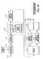
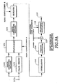
- Figs. 1A and 1B are block diagrams showing a first embodiment of a transmitter and a receiver using the variable rate transmission method relating to the present invention.
- Fig. 1A shows the configuration of the transmitter.
- a transmitted data sequence applied to an input terminal 101A is delivered to an error detecting encoder 102 and a frame memory 103.
- the frame memory 103 holds the data with the number of bits to be transmitted in one frame period.
- the error detecting encoder 102 calculates the error detecting code (CRC bits, for example) of the transmitted data of one frame.
- a multiplexer 104 outputs for each frame a data sequence consisting of the calculated error detecting code followed by the transmitted data.
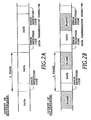
- Figs. 2A and 2B illustrate the data sequences output from the multiplexer 104.
- Fig. 2A illustrates the data sequence when the transmission rate of the data is maximum
- Fig. 2B illustrates the data sequence when the transmission rate is less than the maximum.
- an idle time (a blank) takes place in each frame when the transmission rate is less than the maximum rate.
- the error detecting code is inserted at a fixed position in each frame. For example, in Figs. 2A and 2B , it is placed at the initial position of the frame.
- the data sequence of one frame, into which the error detecting code is inserted undergoes error correcting encoding through an error correcting encoder 105, and is input to an interleaver 106.
- the interleaver 106 includes a controller 106A and a frame memory 106B.
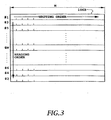
- Fig. 3 is a schematic diagram illustrating the frame memory 106B of the interleaver 106.
- the interleaver 106 reads the data sequence of one frame in a direction different from that of writing to the frame memory 106B. That is, the interleaver 106 reads in the direction of columns the transmitted data which has been written in the direction of rows of the frame memory 106B. The data sequence thus interleaved is rewritten in the other side of the frame memory 106B.
- numbers #1 - #N attached to the left of the frame memory 106B indicate the order of writing the data, which will be described later in the sixth embodiment.
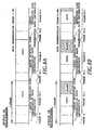
- Fig. 4 illustrates the frame structure of the data sequence output from the frame memory 106B.
- the data segments corresponding to individual rows of the frame memory 106B are called slots. Accordingly, if one side of the frame memory 106B corresponding to one frame consists of M bits/row * N rows as shown in Fig. 3 , one slot consists of N bits and one frame consists of M slots, and the number of bits of one frame is N*M bits.
- the transmitted data undergoes error correcting encoding by the error correcting encoder 105, followed by the interleaving by the interleaver 106. As a result, the probability increases that the transmitted data can be corrected using the error correcting code for burst mode errors.
- the frame memories 103 and 106B in Fig. 1A each have two sides (side-A and side-B) to hold two frame data, respectively.
- the first frame data is written in the side-A of the frame memory 103, and then written in the side-A of the frame memory 106B after the error correcting encoding and the interleaving.
- the second frame data is written in the side-B of the frame memory 103, and then written in the side-B of the frame memory 106B after the error correcting encoding and the interleaving.
- Using the side-A and side-B alternately makes it possible to continue the processing of a series of data sequences.
- Fig. 5 illustrates the processing using the two-side frame memories.
- the input data sequence of one frame is written in the frame memory 103, undergoes the combined processing of the error correcting encoding and the interleaving, and then the processed data is written into the frame memory 106B.
- the transmitted data sequence is delayed by an amount of one frame interval plus the processing time.
- the data sequence output from the frame memory 106B is phase modulated by a primary modulator 108, followed by phase modulation (spreading) through a secondary modulator 109.
- the secondary modulator 109 uses a spreading code sequence with a chip rate of integer multiple (usually from tens to hundreds of times) of the transmission rate of the transmitted data, thereby outputting the transmitted data from an output terminal 110.
- the primary modulator 108 does not carry out the modulation of the blank in each slot.
- the transmitter carrying out the above-mentioned processing, transmits the variable number of bits in a fixed frame period.
- the spread data is sent at an apparent variable transmission rate.
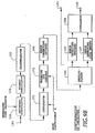
- Fig. 1B is a block diagram showing the receiver.
- the receiver despreads the spread data fed from an input terminal 150 with a secondary demodulator 151.
- the despread data is detected by a primary demodulator 152, and is fed to a deinterleaver 153.
- the deinterleaver 153 includes a controller 153A and a frame memory 153B, with two side arrangement, and operates in the reverse order of the input and output in the interleaver 106 at the transmitter.
- the controller 153A writes the data into the frame memory 153B column by column (slot by slot), and reads the data row by row. This procedure enables the original data sequence of one frame to be recovered, thereby producing the error detecting code and the data sequence following it.
- the error detecting code thus obtained is compared by a comparator 158 with the data sequence held in the error detecting code memory 157 bit by bit of the code.
- the comparator 158 produces a coincident signal from a terminal 160 when the entire bits agrees with each other. If no error has occurred during the transmission, the coincident signal will be output at the right number of bits of the transmitted data, in which case the received data sequence in the received frame is decided correct, and is output from the output terminal 159.
- the data transmission using the transmitter and receiver as described above makes it unnecessary to send from the transmitter to the receiver the information representing the number of bits of the frame. Accordingly, even if the number of bits in the frame (that is, the apparent transmission rate) is varied from frame to frame at the transmitting side, the receiving side can catch up with this correctly. In other words, the variable rate transmission can be achieved in which the apparent transmission rate can be varied frame by frame during the communications. Since the frame length is fixed, the receiver can always identify the frames correctly, even if frames without transmitted data are mixed.
- the comparator 158 can detect (misdetect) the coincident signal at a wrong position.
- the demultiplexer 155 will output either a part of the entire effective data in the frame as effective data, or data consisting of the entire effective data plus superfluous data following it.
- the transmitter and receiver of this embodiment place the error detecting code in the fixed position in the frame, and hence, the probability of the misdetection can be reduced to a very small value by determining the number of bits of the error detecting code greater than that needed for detecting ordinary errors.
- limiting the number of bits allowed in one frame will restrict the position at which the coincident signal of the comparator 158 is obtained, and this can further reduce the probability of outputting the coincident signal at a wrong position.
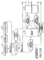
- Figs. 6A and 6B are block diagrams showing a second embodiment of a transmitter and a receiver using the variable rate transmission method relating to the present invention.
- the second embodiment differs from the first embodiment in that it provides the transmission rate information from the transmitter to the receiver. More specifically, it differs in the following points.
- the transmitter is provided with a transmission rate information memory 113.
- the transmission rate information memory 113 is a memory for storing the transmission rate information of the frame data held in the frame memory 103, that is, the information representing the number of bits of the frame data.
- the information is input to the transmission rate information memory 113 from a terminal 101B frame by frame.
- the transmitter sends the data of a variable bit number with the transmission rate information in a fixed frame period.
- the multiplexer 104 inserts the transmission rate information before the error detecting code.
- Figs. 7A and 7B illustrate the output of the multiplexer 104.
- Fig. 7A illustrates the output when the transmission rate of the transmitted data is maximum
- Fig. 7B illustrates the output when the transmission rate is less than the maximum rate.
- an idle time that is, a blank including no data takes place in each frame.
- each frame consists of the transmission rate information, the error detecting code and the transmitted data. The frame differs from that of the first embodiment in that it is provided with the transmission rate information preceding the error detecting code.
- the transmission rate information memory 161 stores the transmission rate information extracted from the received data fed from the error correcting decoder 154.
- the receiver despreads, demodulates and deinterleaves the received data as in the first embodiment.
- the original data sequence of one frame is recovered, and the transmission rate information, the error detecting code and the transmitted data sequence are obtained. These are fed to the error correcting decoder 154 to undergo the error correcting encoding.
- the transmission rate information contained in the recovered output of the error correcting decoder 154 is input to the transmission rate information memory 161 to be stored, and is output from the terminal 162.
- the transmitted data sequence and the error detecting code are separated by the demultiplexer 155.
- the transmitted data is fed to the error detecting encoder 156, and the terminal 159 from which it is output as the received data.
- the error detecting code is input to the error detecting code memory 157 to be stored.
- the error detecting encoder 156 carries out the same error detecting encoding as that of the transmitter to the last bit of the input data sequence. The last bit is fed from the transmission rate information memory 161. This is the very point which differs from the first embodiment. After that, the processing proceeds as in the first embodiment.
- the comparator 158 compares the error detecting code output from the error detecting encoder 156 with the contents of the error detecting code memory 157 bit by bit, and outputs the coincident signal from the terminal 160 when all the bits agree with each other. If no error occurs during the transmission, the coincident signal is output to the terminal 160, in which case, it is decided that the transmitted data in the frame output from the terminal 159, and the transmission rate information output from the terminal 162 are both received correctly.
- the decoded result of the transmission rate information is first obtained by sequentially applying the maximum likelihood decoding, and then the error correcting decoding of the transmitted data is carried out to the last bit designated by the transmission rate information.
- increasing reliability is obtained of the decoded result of the transmission rate information as the input signal stored in the decoder increases, that is, as the encoded data sequence following the transmission rate data increases, because of the characteristics of the decoder. For this reason, it is preferable that the greatest possible fixed length data sequence such as error detecting code other than the transmitted data be placed immediately after the transmission rate information without interruption.
- the following method can be used to decode the transmitted data to the last bit.
- the transmitter adds tail bits immediately after the last bit, and performs the error correcting encoding on them.
- the receiver completes the error correcting decoding with the tail bits.
- the transmitter can insert the tail bits after the transmission rate information to be transmitted, and the receiver can once complete decoding at the tail bits, and then restart the decoding of the transmitted data to the last bit.
- Figs. 8A and 8B show the data sequence output from the multiplexer 104 of the transmitter in this case.
- the receiver can obtain the number of bits of the effective data of the current frame before deinterleaving it. This makes it possible to eliminate the frame delay involved in the deinterleaving. As a result, the power of the received signal can be measured precisely during the transmission of the current effective data. This is required to achieve the transmission power control, in which the power of the received signal must be measured with minimum delay time to be fed back to the transmitting side.
- a dummy frame is required to send the transmission rate information of the first frame at the beginning of the successive data transmission.
- the receiver performs the reencoding and coincident detection of the error detecting code to confirm the effectiveness of the transmitted data for each frame. Therefore, even if the received transmission rate information (that is, information representative of the number of transmitted bits in the frame) is wrong, the possibility (misdetection) of outputting transmitted data of wrong length can be reduced to a minimum. This makes possible to achieve a highly reliable, variable rate data transmission.
- the received transmission rate information that is, information representative of the number of transmitted bits in the frame
- an amount of the transmitted data per frame reduces.
- a burst transmission occurs in which short data sequence is transmitted intermittently because the frame length is fixed. If it is known in advance that the number of bits (the total bits of the error detecting code and the data sequence) per frame is equal to or less than 1/K of the maximum bits of the frame where K is a positive integer, the burst mode transmission can be avoided by sending the data sequence with its individual bits repeated K times after carrying out the error correcting encoding of the data sequence.
- the following embodiments are an example of such a data transmission.
- Figs. 9A and 9B are block diagrams showing a third embodiment of the transmitter and receiver using the variable rate transmission method relating to the present invention.
- This embodiment mainly differs from the first embodiment as shown in Figs. 1A and 1B in the following.
- the transmitter is provided with a repeater 121 connected next to the error correcting encoder 105.
- the repeater 121 has a function to repeat each bit in the frame K times (twice in Fig. 10(C) ).
- a new data sequence is generated in which the bits of the output data from the error correcting encoder 105 as shown in Fig. 10(B) are each repeated K times.
- a multiplier 123 for controlling the transmission power is connected between the primary modulator 108 and the secondary modulator 109.
- the data output from the repeater 121 is interleaved by the interleaver 106, followed by primary and secondary modulation, and the transmission thereof. Since the same bit is transmitted K times, the average transmission power of the bit increases by a factor of K as compared with the transmission power when repeating is not performed. The average transmission power is proportional to the power of interference to other users. To prevent the average transmission power increase due to the repetition of bits, the system in Fig. 9A is provided with the multiplier 123 connected after the primary modulator 108 so that the output of the primary modulator 108 is multiplied by the power factor of 1/K.
- the receiver is provided with an integrator 171 and a thinning out circuit 172, which are connected immediately after the deinterleaver 153.
- the integrator 171 obtains an integral for each continuous K symbols of the deinterleaved received data sequence.
- the thinning out circuit 172 thins out the integrated output at every K symbol interval, and outputs the result. Both the circuits 171 and 172 carry out this processing only to the repeated portion of the transmitted data so that the other additional bits are passed without change.
- Fig. 10(A) shows the output of the multiplexer 104.
- Such arrangement of the frame including blanks will cause burst mode transmission.
- the error detecting code and transmitted data output from the error correcting encoder 105 ( Fig. 10(B) ) are input to the repeater 121 which repeats each bit K times ( Fig. 10(C) ).
- the receiver recovers the same data sequence as the output of the error correcting encoder 105 of the transmitter through the integrator 171 and the thinning out circuit 172. After that, the same processing as that of the first embodiment is carried out, thereby resulting in the final received data sequence.
- the number K of repetition used in the receiver must be identical to that used in the transmitter. Accordingly, it is necessary to send K to the receiver before the data transmission.
- This embodiment can achieve the variable rate transmission without the burst mode transmission even if the data transmission rate is substantially lower than the maximum rate.
- Figs. 11A and 11B are block diagrams showing a fourth embodiment of the transmitter and receiver using the variable rate transmission method relating to the present invention.
- This embodiment is a combination of the second and third embodiments. Specifically, the transmission rate information memory 113 and transmission rate information memory 161 are added to the transmitter and receiver of the third embodiment, respectively.
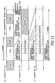
- Fig. 12 is a diagram corresponding to Fig. 10 of the second embodiment.
- the present embodiment is characterized in that the transmission rate information is inserted immediately before the transmitted data. Since the other operation can be easily understood from the second and third embodiments, the description thereof will be omitted here.
- the above described first to fifth embodiments do not use pilot symbols.
- the pilot symbols have a predetermined fixed pattern, and are sent intermittently with transmitted data into which the pilot symbols are inserted periodically, or sent continuously through a dedicated channel.
- a receiver extracts the pilot symbols of the known pattern, and estimates fading of transmission paths to compensate fluctuations of a received signal due to fading.
- the following embodiments relate to the variable rate transmission system including such pilot symbols.
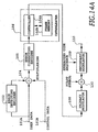
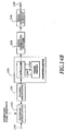
- Figs. 14A and 14B are block diagrams showing a sixth embodiment of the transmitter and receiver using the variable rate transmission method relating to the present invention.
- the transmitter of Fig. 14A differs from that of Fig. 1A in the following.
- the receiver as shown in Fig. 14B differs from the receiver as shown in Fig. 1B in the following.
- the error detection circuit 144 shifts the data in each frame bit by bit, successively divides the data by predetermined data, and decides that the error detecting code is detected at the point where the data can be divided. Since the length of the error detecting code is known in advance, the last bit of the transmitted data can be found by identifying the error detecting code. Thus, the transmitted data can be extracted.
- the user data sequence applied to the input terminal 101A is divided into data with a duration of a predetermined frame period Tf.
- the error detecting encoder 102 calculates a check code (CRC bits, for example) for each frame of the user data, and supplies it to the multiplexer 104.
- the multiplexer 104 adds the control data fed from the input terminal 101B before the user data in each frame, and adds the check code from the error detecting encoder 102 at the end of the data in the frame, thereby forming one frame data.
- Fig. 16 illustrates the data output from the multiplexer 104. As shown in Fig. 16 , blanks appear in the frame when the total bit number (which corresponds to the transmission rate) of the control data, user data and check code is less than the maximum bit number (maximum rate) that can be transmitted in one frame
- the transmitted data of one frame undergoes error correcting encoding by the error correcting encoder 105, and is fed to the interleaver 106.
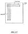
- the interleaver 106 reads the data of one frame which has been written in the frame memory 106B in the direction different from the writing direction as shown in Fig. 17 . That is, the transmitted data of one frame written in the row direction of the interleaver 106 is read in the column direction at a predetermined rate.
- the read data undergoes phase modulation by the primary modulator 108, and is fed to the pilot symbol inserting circuit 130.
- the pilot symbol inserting circuit 130 periodically inserts the pilot symbols of a known pattern into the data supplied, thereby forming a modulated symbol sequence.
- Fig. 15A is a block diagram showing the configuration of the pilot symbol inserting circuit 130.
- the pilot symbols of a known pattern which are periodically generated by a pilot symbol generator 131, are fed to a multiplexer 132.
- the multiplexer 132 multiplexes the data fed from the primary modulator 108 and the pilot symbols, thereby generating a modulated symbol sequence.
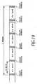
- Fig. 18 illustrates the arrangement of the modulated symbol sequence.
- a section sandwiched by the pilot symbols which are inserted periodically is called a slot.
- one slot consists of N bits and one frame consists of M slots, one frame consists of N*M bits.
- the receiver receiving the pilot symbols of the known pattern which have been periodically inserted into the data to be transmitted, estimates the phase of each symbol in the slot, and corrects the phase by using the pilot symbols. This compensates the phase of each symbol varied by the fading in the transmission. This processing is carried out by the primary demodulator 152.
- Fig. 15B is a block diagram showing the configuration of the primary demodulator 152.
- the despread signal fed from the secondary demodulator 151 is supplied to the quasi-coherent detector 181.
- the quasi-coherent detector 181 quasi-coherent detects the despread signal using the carrier of the same frequency as that of the transmitter, and supplies the detected output to a demultiplexer 182.
- the demultiplexer 182 divides the data obtained by the quasi-coherent detection into data symbols and the pilot symbols, and supplies the data symbols to a compensator 183 and the pilot symbols to a transfer function estimator 184.
- the transfer function estimator 184 estimates the transfer function of the propagation path from the pilot symbols, and supplies the transfer function to the compensator 183.
- the compensator 183 compensates the phases of the data symbols in response to the estimated transfer function, and provides the compensated output to a decision circuit 185.
- the decision circuit 185 decides the compensated data, and outputs the data symbols. Details of this processing is disclosed in the above-mentioned paper of S. Sampei.
- Fig. 3 illustrates the arrangement of the frame data in the frame memory 106B of the interleaver 106.
- the number of bits in a row of the frame memory 106B is assumed to be equal to the number of slots M constituting one frame.
- the number of bits (that is, the number of rows) in one column is assumed to be equal to the number of bits N of one slot.
- One frame data including the check code for error detection is written bit by bit into the row direction of the frame memory 106B which is represented in the form of two-dimensions.
- the writing of one frame is carried out alternately from the top and bottom of the frame memory 106B row by row.
- the numbers attached to the rows of Fig. 3 represent the writing order. Since the control data is placed at the initial position of the frame, it is written in the rows of low numbers. In other words, this important data is written at the initial and final positions of the frame in the frame memory 106B.
- the data in the frame memory 106B is read in the column direction bit by bit.
- the column numbers 1-M correspond to the slot numbers of Fig. 18 .
- the important data control data
- Fig. 19 a blank appears in the slot, which corresponds to the blank of each frame in Fig. 16 .
- the receiver is provided with the deinterleaver 153 in correspondence with the interleaver 106.
- the deinterleaver 153 recovers the frame data from the slot data in the procedure opposite to that of the interleaver 106.
- the important control data can be transmitted in the portions near the pilot symbols at which errors will least occur.
- the error rate of the received data reduces as the received power increases.
- the data error rate can be reduced by controlling the transmission power in accordance with the degree of importance of the transmitted data.
- the following seventh embodiment is implemented along the lines of this.
- Fig. 20 is a block diagram showing the seventh embodiment of the transmitter using the variable rate transmission method relating to the present invention.
- the transmitter differs from the transmitter of the sixth embodiment shown in Fig. 14A in that it is provided with a multiplier 141 next to the pilot symbol inserting circuit 130.
- the multiplier 141 multiplies the output of the pilot symbol inserting circuit 130 as shown in Fig. 19 by a predetermined power coefficient.
- the multiplier 141 multiplies a larger power coefficient as the degree of importance of the data increases. For example, the important pilot symbols and control data thereabout are multiplied by a maximum power coefficient.
- Fig. 21 is a schematic diagram illustrating the relationships between the types of data and the power coefficients. Predetermined numbers of bits are assigned to respective data in accordance with their types except for the blanks. The blanks are filled with a particular code to distinguish them from the other portions, and are multiplied by zero so that they are not transmitted. In other words, when the code representing the blanks, the power coefficient is placed zero so that their transmission is suppressed.
- the multiplier 141 of the power coefficient is inserted before the secondary modulator 109, it can be placed after the secondary modulator 109.
- Fig. 21 illustrates the control behavior of the transmission power in accordance with the degree of importance of the data.
- the foregoing first embodiment describes an example which transmits the data at various rates without providing the party with the transmission rate information representing the number of bits of the data in each frame.
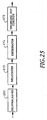
- Figs. 22 and 23 show another embodiment which does not send the transmission rate information to the receiver.
- the transmitter of this embodiment is similar to that of the seventh embodiment as shown in Fig. 20 .
- Fig. 22 illustrates the transmitted bit sequence written in the frame memory of the interleaver 106 of the transmitter when the transmission rate is less than the maximum transmission rate of the transmitter.
- the error detecting code. (check code) is added to the end of the transmitted data in each frame, and a blank follows that.
- the transmitted data in the frame memory 106B is read column by column at a fixed rate, and is sequentially mapped to each slot to be sent.
- the space in which the transmitted data is absent corresponds to the blank in each slot.
- the primary modulator 108 does not modulate the blanks.
- the transmitted data of the variable bit number is transmitted in a fixed frame interval, at a constant transmission rate.
- Fig. 23 shows the major portion of the receiver for receiving the data thus transmitted.
- the receiver recovers the data of each frame by the deinterleaver 153 in the opposite procedure as that of the interleaver 106 in the transmitter.
- the procedure is the same as that of the first embodiment.
- the data of one frame is fed to the error detection circuit 144 connected to the output of the interleaver 106.
- the error detection circuit 144 detects the last bit of the transmitted data in the manner as described before. More specifically, the error detection circuit 144, shifting the data in the frame bit by bit, successively divides the data by the predetermined data, and decides that the error detecting code is received and the correct transmitted data is obtained at the point at which the data can be divided.
- the transmitted original data is obtained when the received data is output at that point.
- Transmitting and receiving in this way eliminates the need to send each time the transmission rate information representing the amount of data in each frame.
- the receiver can recover the data correctly even if the amount (apparent transmission rate) of the transmitted data in each frame varies. This is because even if the transmitted data is absent, the receiver can recognize this because of the fixed frame period.
- variable rate transmission is implemented in which the apparent transmission rate (actually the bit number of data) can vary from frame to frame, even if the transmission rate information is not sent. It is necessary for the conventional variable rate transmission which does not send the transmission rate information in advance, to predetermine at intervals the values taken by the transmission rate, and this limits the number of transmission rates that can be handled. In contrast, this embodiment can achieve the transmission at any desired rates.
- a decision that no error has occurred can be made at a wrong position if an error takes place in the transmission.
- only a part of the transmitted data may be output as the effective data, or the transmitted data plus superfluous random data may be output as the effective data.
- the number of bits of the transmitted data can be set at intervals, and this will make it possible to reduce the erroneous output of the data because the error detecting points are spaced apart.
- This embodiment corresponds to the third embodiment, which avoids the burst mode transmission involved in the intermittent transmission of short data. If the transmission rate is equal to or less than 1/K of the maximum rate allowed by a single transmitting channel, the transmitted data undergoes the error correcting encoding, and each bit of the encoded data is repeated K times to form the frame data to be transmitted. The repetition number K is sent to the receiver at the beginning of the transmission.
- the burst mode transmission can be avoided.
- the eighth embodiment can be used in combination with the ninth embodiment. In this case, if the repetition rate K has been sent to the receiver at the beginning of communications, the can recover the transmitted data in accordance with the error detecting information even if the transmission rate varies frame by frame. Thus, excessive burst mode transmission can be avoided.
- a high speed data transmission requires to send data of more than N*M bits per frame. This will be handled by using a plurality of channels to carry out the parallel transmission of the data.
- the tenth embodiment is provided for achieving such a high speed transmission.
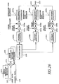
- Fig. 26 shows the tenth embodiment of the transmitter using the variable rate transmission method relating to the present invention
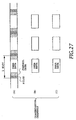
- Fig. 27 illustrates the frame arrangement to be transmitted.
- Figs. 26 and 27 show a case in which three frames are transmitted simultaneously (3 channels). A higher speed data transmission will demand more channels. The receiver is informed of the channel numbers used for the high speed transmission preceding the start of the transmission. The capacity of the frame memory of the interleaver 106 must be reserved at least twice that for storing the entire frames simultaneously transmitted. In addition, the frame memory must be accessible from a plurality of channels at the same time. Phase controllers 146b and 146c will be described in the next eleventh embodiment because this tenth embodiment describes the case in which the phase control is not performed.
- the interleaver 106 successively writes the data to be transmitted into the frame memory at a high speed to form a plurality of transmitted frames. Since the control data is placed at the initial position of each frame, it is written in the side-a of the frame memory. When the side-a of the frame memory fills up, the data is written into the side-b of the frame memory. When the side-b of the frame memory fills up, the data is written into the side-c of the frame memory. The writing to the frame memory is performed at a speed higher than a normal transmission rate (three or more times the normal rate in this case).
- Reading the plurality of frames simultaneously from this frame memory is carried out at the rate equal to the normal transmission rate.
- the writing to and reading from each of the sides of the frame memory is performed as in the sixth embodiment.
- the data associated with the side-a to side-c undergo the primary modulation by primary modulators 108a - 108c, are spread by secondary modulators 109a - 109c using different spreading code sequences, and are summed up by an adder 148 to be transmitted.
- Fig. 27 illustrates the frame structure of each transmission channel when the high speed transmission is implemented by the simultaneous transmission using a plurality of channels. As shown in this figure, he control data and the pilot symbols are sent through one channel even if a plurality of transmission channels are used. The other channels do not transmit the portions corresponding to the pilot symbols and the control data. This makes it possible to reduce the interference power to other users.
- the receiver To receive the data transmitted by the plurality of channels, the receiver must comprise the same number of receiving channels.
- the receiver using the pilot symbols transmitted through one of the channels, compensates the received signals of the other channels.
- the control data of one of the channels is also used to control the other channels.
- the deinterleaver corresponding to the interleaver 106 performs writing and reading in the procedure opposite to that of the transmitter.
- the frame memory of the deinterleaver of the receiver must satisfy the condition that it can write a plurality of data at the same time, and read the plurality of data which have been written at a high speed (three times the normal speed in this case).
- the high speed data transmission is implemented by assigning the transmitted data to a plurality of transmission channels, by carrying out the primary modulation of them, and by spreading them into wideband signals by using multiple spreading codes to be sent.
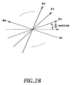
- the phase after the primary modulation of each channel is either 0 (when the transmitted data is "1") or ⁇ radian (when the transmitted data is "0").
- the spread signals also take phases of 0 or ⁇ radian. Accordingly, if N spread signals are combined without shifting their phases, the amplitude increases by a factor of N, and hence a transmission power amplifier of high peak power is required.
- phase control is carried out with the phase controllers 146b and 146c shown in Fig. 26 .
- Fig. 28 illustrates the phase control when N signals are simultaneously sent.
- the peak of the transmission power can be limited as compared with the simple combining.
- phase controller 146b rotates the phase by ⁇ /3
- phase controller 146c rotates the phase by 2 ⁇ /3.
- the phase controllers 146b and 146c are inserted before the secondary modulators 109b and 109c in Fig. 26 , this is not essential.
- the phase controllers 146b and 146c may be placed next to the secondary modulators 109b and 109c because it is enough that the phases are shifted of the carriers which have undergone the secondary modulation.
- the receiver since the receiver knows the phase differences of the respective channels, it must correct the phase differences with phase controllers for respective channels. After correcting the phase differences of the channels, the receiver, using the pilot symbols sent through one channel, can compensate the data of the other channels as in the tenth embodiment.
Landscapes
- Engineering & Computer Science (AREA)
- Computer Networks & Wireless Communication (AREA)
- Signal Processing (AREA)
- Quality & Reliability (AREA)
- Detection And Prevention Of Errors In Transmission (AREA)
- Error Detection And Correction (AREA)
- Communication Control (AREA)
- Mobile Radio Communication Systems (AREA)
Claims (4)
- Übertragungsverfahren mit variabler Rate zum Übertragen von Informationsdaten variabler Länge, wobei die Informationsdaten in einen Rahmen einer festen Zeitlänge gestellt werden, und unter Verwendung eines Code-Division-Multiple-Access-Verfahrens, mit den Schritten zum:Erzeugen eines Fehlererfassungscodes der Informationsdaten;Verknüpfen der Informationsdaten und des Fehlererfassungscodes in Daten;Fehlerkorrekturkodieren der Daten, in denen die Informationsdaten und der Fehlererfassungscode verknüpft wurden;Verschränken der fehlerkorrekturkodierten Daten;Modulieren der verschränkten fehlerkorrekturkodierten Daten; undÜbertragung der verschränkten fehlerkorrekturkodierten Daten in dem Rahmen mit einer festen Übertragungsrate, wobei der Schritt zum Verknüpfen den Fehlererfassungscode direkt nach den Informationsdaten anordnet, und das Übertragungsverfahren gekennzeichnet ist, durchwenn die Summe der Anzahl von Bits der Informationsdaten und des Fehlererfassungscodes geringer als die maximale Nummer von Bits ist, die in dem Rahmen übertragen werden können, der Schritt zum Übertragen eine Übertragung an dem Ende des Rahmens für einen einzelnen freien Abschnitt aussetzt, in dem die Informationsdaten und der Fehlererfassungscode fehlen.
- Übertragungseinheit mit variablen Rate zum Übertragen von Informationsdaten variabler Länge, in dem die Informationsdaten in einen Rahmen einer festen Zeitlänge gestellt werden, und unter Verwendung eines Code-Division-Multiple-Access-Verfahrens, umfassend:ein Mittel zum Erzeugen eines Fehlererfassungscodes der Informationsdaten;ein Mittel zum Verknüpfen der Informationsdaten und des Fehlererfassungscodes in Daten;ein Mittel zum Fehlerkorrekturkodieren der Daten, in denen die Informationsdaten und der Fehlererfassungscode verknüpft wurden;ein Mittel zum Verschachteln der fehlerkorrekturkodierten Daten;ein Mittel zum Modulieren der verschachtelten fehlerkorrekturkodierten Daten; undein Mittel zum Übertragen der modulierten verschachtelten fehlerkorrekturkodierten Daten in dem Rahmen mit einer festen Übertragungsrate,wobei das Mittel zum Verknüpfen ferner ausgelegt ist zum Anordnen des Fehlererfassungscodes direkt nach den Informationsdaten, und die Übertragungseinheit mit variabler Rate dadurch gekennzeichnet ist, dass,wenn die Summe der Anzahl von Bits der Informationsdaten und des Fehlererfassungscodes geringer als die maximale Anzahl von Bits ist, die in dem Rahmen übertragen werden können, das Mittel zum Übertragen ferner ausgelegt ist, eine Übertragung an dem Ende des Rahmens für einen einzelnen freien Bereich auszusetzen, in dem die Informationsdaten und der Fehlererfassungscode fehlen.
- Empfangsverfahren mit variabler Rate zum Empfangen eines Signals, in dem Informationsdaten variabler Länge in einen Rahmen einer festen Zeitlänge gestellt wurden, und das unter Verwendung eines Code-Division-Multiple-Access-Verfahrens übertragen wurde, wobei der Rahmen eine feste Übertragungsrate aufweist, das Signal die Informationsdaten und einen Fehlererfassungscode der Informationsdaten enthält, der Fehlererfassungscode direkt nach den Informationsdaten angeordnet ist, das Signal ferner einen einzelnen freien Bereich an dem Ende des Rahmens aufweist, wo die Informationsdaten und der Fehlererfassungscode fehlen, wenn die Summer der Anzahl von Bits der Informationsdaten und des Fehlererfassungscodes geringer als die maximale Anzahl von Bits ist, die in dem Rahmen übertragen werden können, wobei das Empfangsverfahren die Schritte umfasst zum:Demodulieren des empfangenen Signals;Entschachteln von Daten, die in dem demodulierten Signal enthalten sind;Fehlerkorrekturdekodieren der entschachtelten Daten;Erfassen eines Fehlererfassungscodes für den Rahmen in den fehlerkorrekturdekodierten entschachtelten Daten; undWiederherstellen der Informationsdaten durch Feststellen eines End-Bits der Informationsdaten an einem Punkt, der dem Punkt, an dem der Fehlererfassungscode erfasst wird, um die Anzahl von Bits des Fehlererfassungscodes vorausgeht.
- Empfänger mit variabler Rate zum Empfangen eines Signals, in dem variable Längeninformationsdaten in einen Rahmen einer festen Zeitlänge gestellte wurden, und das unter Verwendung eines Code-Division-Multiple-Access-Verfahrens übertragen wurde, wobei der Rahmen eine feste Übertragungsrate aufweist, das Signal die Informationsdaten und einen Fehlererfassungscode der Informationsdaten enthält, der Fehlererfassungscode direkt nach den Informationsdaten angeordnet ist, das Signal ferner einen einzelnen freien Bereich an dem Ende des Rahmens enthält, wo die Informationsdaten und der Fehlererfassungscode fehlen, wenn die Summe der Anzahl von Bits der Informationsdaten und des Fehlererfassungscodes geringer als die maximale Anzahl von Bits ist, die in dem Rahmen übertragen werden können, wobei der Empfänger umfasst:ein Mittel zum Demodulieren des empfangenden Signals;ein Mittel zum Entschachteln von Daten, die in dem demodulierten Signal enthalten sind;ein Mittel zum Fehlerkorrekturdekodieren der entschachtelten Daten;ein Mittel zum Erfassen eines Fehlererfassungscodes für den Rahmen in den fehlerkorrekturdekodierten entschachtelten Daten; undein Mittel zum Wiederherstellen der Informationsdaten durch Feststellen eines End-Bits der Informationsdaten an einem Punkt, der dem Punkt, an dem der Fehlererfassungscode erfasst wird, um die Anzahl von Bits des Fehlererfassungscodes vorausgeht.
Applications Claiming Priority (8)
| Application Number | Priority Date | Filing Date | Title |
|---|---|---|---|
| JP3570295 | 1995-02-23 | ||
| JP3570295 | 1995-02-23 | ||
| JP14772895 | 1995-06-14 | ||
| JP14772895 | 1995-06-14 | ||
| JP32482395 | 1995-12-13 | ||
| JP32482395 | 1995-12-13 | ||
| EP03077343A EP1357689B1 (de) | 1995-02-23 | 1996-02-23 | Verfahren zur Übertragung variabler Bitraten und dieses verwendende Sender |
| EP96903224A EP0758168B2 (de) | 1995-02-23 | 1996-02-23 | Verfahren zur übertragung variabler bitraten und dieses verwendende sender und empfänger |
Related Parent Applications (3)
| Application Number | Title | Priority Date | Filing Date |
|---|---|---|---|
| EP03077343A Division EP1357689B1 (de) | 1995-02-23 | 1996-02-23 | Verfahren zur Übertragung variabler Bitraten und dieses verwendende Sender |
| EP96903224.2 Division | 1996-08-29 | ||
| EP03077343.6 Division | 2003-07-25 |
Publications (3)
| Publication Number | Publication Date |
|---|---|
| EP1545026A1 EP1545026A1 (de) | 2005-06-22 |
| EP1545026B1 true EP1545026B1 (de) | 2012-06-13 |
| EP1545026B8 EP1545026B8 (de) | 2012-07-18 |
Family
ID=27288845
Family Applications (3)
| Application Number | Title | Priority Date | Filing Date |
|---|---|---|---|
| EP96903224A Expired - Lifetime EP0758168B2 (de) | 1995-02-23 | 1996-02-23 | Verfahren zur übertragung variabler bitraten und dieses verwendende sender und empfänger |
| EP03077343A Expired - Lifetime EP1357689B1 (de) | 1995-02-23 | 1996-02-23 | Verfahren zur Übertragung variabler Bitraten und dieses verwendende Sender |
| EP05075561A Expired - Lifetime EP1545026B8 (de) | 1995-02-23 | 1996-02-23 | Verfahren zur Übertragung variabler Bitraten und dieses verwendende Sender und Empfänger |
Family Applications Before (2)
| Application Number | Title | Priority Date | Filing Date |
|---|---|---|---|
| EP96903224A Expired - Lifetime EP0758168B2 (de) | 1995-02-23 | 1996-02-23 | Verfahren zur übertragung variabler bitraten und dieses verwendende sender und empfänger |
| EP03077343A Expired - Lifetime EP1357689B1 (de) | 1995-02-23 | 1996-02-23 | Verfahren zur Übertragung variabler Bitraten und dieses verwendende Sender |
Country Status (7)
| Country | Link |
|---|---|
| US (1) | US5896374A (de) |
| EP (3) | EP0758168B2 (de) |
| KR (1) | KR100220344B1 (de) |
| CN (2) | CN1078412C (de) |
| CA (1) | CA2188455C (de) |
| DE (2) | DE69633891T3 (de) |
| WO (1) | WO1996026582A1 (de) |
Families Citing this family (92)
| Publication number | Priority date | Publication date | Assignee | Title |
|---|---|---|---|---|
| JP3087886B2 (ja) * | 1995-10-24 | 2000-09-11 | 株式会社エヌ・ティ・ティ・ドコモ | Cdma移動通信の再送制御方法 |
| US6678311B2 (en) * | 1996-05-28 | 2004-01-13 | Qualcomm Incorporated | High data CDMA wireless communication system using variable sized channel codes |
| KR100292309B1 (ko) * | 1996-06-24 | 2001-06-01 | 다치카와 게이지 | 데이터 전송 방법, 데이터 전송 시스템과 송신기및 수신기 |
| JP3666155B2 (ja) * | 1996-12-26 | 2005-06-29 | ソニー株式会社 | 通信方法、送信装置及び受信装置 |
| EP1492376A1 (de) | 1997-04-17 | 2004-12-29 | NTT DoCoMo, Inc. | Basisstation für mobile Telekommunikationsanordnung |
| RU2313176C2 (ru) * | 1997-05-14 | 2007-12-20 | Квэлкомм Инкорпорейтед | Абонентский блок и способ его использования в беспроводной системе связи |
| EP0915588A4 (de) * | 1997-05-16 | 2004-10-27 | Nippon Telegraph & Telephone | Verfahren, sender und empfänger zur übertragung von rahmen mit variabler länge |
| US6081536A (en) | 1997-06-20 | 2000-06-27 | Tantivy Communications, Inc. | Dynamic bandwidth allocation to transmit a wireless protocol across a code division multiple access (CDMA) radio link |
| US6542481B2 (en) | 1998-06-01 | 2003-04-01 | Tantivy Communications, Inc. | Dynamic bandwidth allocation for multiple access communication using session queues |
| US6421333B1 (en) * | 1997-06-21 | 2002-07-16 | Nortel Networks Limited | Channel coding and interleaving for transmission on a multicarrier system |
| JP3655057B2 (ja) * | 1997-07-19 | 2005-06-02 | 松下電器産業株式会社 | Cdma送信装置及びcdma送信方法 |
| DE19736434C3 (de) | 1997-08-21 | 2002-08-22 | Nokia Mobile Phones Ltd | Verfahren und Vorrichtungen zur Erkennung der Position von in einem seriellen Datenempfangsstrom liegenden Datenpaketen |
| JP3217307B2 (ja) * | 1997-11-18 | 2001-10-09 | 沖電気工業株式会社 | 無線送信装置 |
| US6222832B1 (en) | 1998-06-01 | 2001-04-24 | Tantivy Communications, Inc. | Fast Acquisition of traffic channels for a highly variable data rate reverse link of a CDMA wireless communication system |
| US9525923B2 (en) | 1997-12-17 | 2016-12-20 | Intel Corporation | Multi-detection of heartbeat to reduce error probability |
| US7394791B2 (en) | 1997-12-17 | 2008-07-01 | Interdigital Technology Corporation | Multi-detection of heartbeat to reduce error probability |
| JP4194755B2 (ja) * | 1998-01-22 | 2008-12-10 | ブリティッシュ・テレコミュニケーションズ・パブリック・リミテッド・カンパニー | 狭帯域干渉を伴うスペクトラム拡散信号の受信 |
| JP3381794B2 (ja) * | 1998-02-14 | 2003-03-04 | サムスン エレクトロニクス カンパニー リミテッド | 専用制御チャネルを備える移動通信システムのデータ通信装置及び方法 |
| KR100255328B1 (ko) | 1998-02-18 | 2000-05-01 | 윤종용 | 음성 신호의 기록/재생이 가능한 이동 무선 전화기 및그 제어 방법 |
| JP3981899B2 (ja) * | 1998-02-26 | 2007-09-26 | ソニー株式会社 | 送信方法、送信装置及び受信装置 |
| JP3741858B2 (ja) * | 1998-03-19 | 2006-02-01 | 富士通株式会社 | 適応変調方式 |
| JP3214466B2 (ja) * | 1998-04-07 | 2001-10-02 | 日本電気株式会社 | 移動通信システム及びその通信制御方法並びにそれに用いる基地局及び移動局 |
| EP1122965B1 (de) * | 1998-04-17 | 2004-01-21 | Matsushita Electric Industrial Co., Ltd. | Funkkommunikationsgerät und Verfahren zur Einstellung der Übertragungsrate |
| US8134980B2 (en) | 1998-06-01 | 2012-03-13 | Ipr Licensing, Inc. | Transmittal of heartbeat signal at a lower level than heartbeat request |
| US7221664B2 (en) * | 1998-06-01 | 2007-05-22 | Interdigital Technology Corporation | Transmittal of heartbeat signal at a lower level than heartbeat request |
| DE69936019T2 (de) * | 1998-07-24 | 2007-08-30 | Matsushita Electric Industrial Co. Limited, Kadoma | CDMA-Funkübertragungssystem und -verfahren |
| US6310869B1 (en) * | 1998-08-31 | 2001-10-30 | Qualcomm Incorporated | Method and apparatus for reducing amplitude variations and interference in communication signals, such as in wireless communication signals employing inserted pilot symbols |
| US6798736B1 (en) * | 1998-09-22 | 2004-09-28 | Qualcomm Incorporated | Method and apparatus for transmitting and receiving variable rate data |
| US6973140B2 (en) | 1999-03-05 | 2005-12-06 | Ipr Licensing, Inc. | Maximizing data rate by adjusting codes and code rates in CDMA system |
| US6785323B1 (en) | 1999-11-22 | 2004-08-31 | Ipr Licensing, Inc. | Variable rate coding for forward link |
| KR100416996B1 (ko) | 1999-05-10 | 2004-02-05 | 삼성전자주식회사 | 이동 통신시스템에서 라디오링크프로토콜에 따른 가변 길이의 데이터 송수신 장치 및 방법 |
| KR100457895B1 (ko) | 1999-05-10 | 2004-11-18 | 가부시키가이샤 엔.티.티.도코모 | 다중화 방법과 다중화 장치 및 데이터 신호 송신 방법과데이터 신호 송신 장치 |
| KR100516671B1 (ko) * | 1999-05-24 | 2005-09-22 | 삼성전자주식회사 | 이동통신시스템에서 라디오링크프로토콜에 따른 가변길이의 데이터 송수신 장치 및 방법 |
| US6259744B1 (en) * | 1999-06-01 | 2001-07-10 | Motorola, Inc. | Method and apparatus for mapping bits to an information burst |
| GB9912846D0 (en) † | 1999-06-02 | 1999-08-04 | Nokia Telecommunications Oy | A method of controlling power |
| JP3613448B2 (ja) | 1999-06-21 | 2005-01-26 | 株式会社エヌ・ティ・ティ・ドコモ | データ伝送方法、データ伝送システム、送信装置および受信装置 |
| ATE329423T1 (de) * | 1999-07-08 | 2006-06-15 | Samsung Electronics Co Ltd | Vorrichtung und verfahren zur steuerung einem demultiplexeur und demultiplexeur für ratenanpassung in einem mobilen übertragungssystem |
| US6732302B1 (en) * | 1999-09-30 | 2004-05-04 | Telefonaktiebolaget Lm Ericcson (Publ) | Blind rate detection in a multiplexed transmission system |
| DE19949007C1 (de) * | 1999-10-11 | 2001-02-08 | Bosch Gmbh Robert | Verfahren zum Empfang von Funksignalen in einer Mobilstation und Mobilstation |
| US7522631B1 (en) | 1999-10-26 | 2009-04-21 | Qualcomm, Incorporated | Method and apparatus for efficient data transmission control in a wireless voice-over-data communication system |
| DE19958425A1 (de) * | 1999-12-03 | 2001-06-13 | Siemens Ag | Datenübertragung in einem Kommunikationssystem |
| WO2001058044A2 (en) | 2000-02-07 | 2001-08-09 | Tantivy Communications, Inc. | Minimal maintenance link to support synchronization |
| FR2810479B1 (fr) | 2000-06-14 | 2002-10-25 | Commissariat Energie Atomique | Procede de transmission de donnees avec code correcteur autosynchronise, codeur et decodeur autosynchronises, emetteur et recepteur correspondants |
| WO2002007372A2 (en) * | 2000-07-13 | 2002-01-24 | Qualcomm Incorporated | Maximum distance block coding scheme |
| US6624767B1 (en) * | 2000-09-06 | 2003-09-23 | Qualcomm, Incorporated | Data buffer structure for asynchronously received physical channels in a CDMA system |
| KR100424460B1 (ko) * | 2000-10-05 | 2004-03-26 | 삼성전자주식회사 | 터보 복호기의 전송률 검출 장치 및 방법 |
| US7613183B1 (en) * | 2000-10-31 | 2009-11-03 | Foundry Networks, Inc. | System and method for router data aggregation and delivery |
| US6940867B1 (en) * | 2000-11-02 | 2005-09-06 | Uniden America Corporation | System and method for transmission of digitized audio samples |
| JP3795743B2 (ja) * | 2000-11-17 | 2006-07-12 | 株式会社エヌ・ティ・ティ・ドコモ | データ伝送方法、データ伝送システム、送信装置および受信装置 |
| US8155096B1 (en) | 2000-12-01 | 2012-04-10 | Ipr Licensing Inc. | Antenna control system and method |
| US7551663B1 (en) | 2001-02-01 | 2009-06-23 | Ipr Licensing, Inc. | Use of correlation combination to achieve channel detection |
| EP2479904B1 (de) | 2001-06-13 | 2017-02-15 | Intel Corporation | Vorrichtungen zur Senden eines Herzschlagsignals mit einem niedrigeren Pegel als eine Herzschlaganforderung |
| JP3583388B2 (ja) * | 2001-06-29 | 2004-11-04 | 松下電器産業株式会社 | データ通信装置およびデータ通信方法 |
| GB2381170A (en) * | 2001-10-19 | 2003-04-23 | Ipwireless Inc | Method and arrangement for asynchronous processing of CCTrCH data |
| KR100520621B1 (ko) * | 2002-01-16 | 2005-10-10 | 삼성전자주식회사 | 가중화된 비이진 반복 누적 부호와 시공간 부호의 부호화방법 및 장치 |
| US7191384B2 (en) * | 2002-10-17 | 2007-03-13 | Qualcomm Incorporated | Method and apparatus for transmitting and receiving a block of data in a communication system |
| US8204079B2 (en) | 2002-10-28 | 2012-06-19 | Qualcomm Incorporated | Joint transmission of multiple multimedia streams |
| US7342977B2 (en) * | 2002-11-26 | 2008-03-11 | Lsi Logic Corporation | Serial data transmitter with bit doubling |
| US7523305B2 (en) | 2003-12-17 | 2009-04-21 | International Business Machines Corporation | Employing cyclic redundancy checks to provide data security |
| US7451381B2 (en) * | 2004-02-03 | 2008-11-11 | Phonex Broadband Corporation | Reliable method and system for efficiently transporting dynamic data across a network |
| CN1951050B (zh) * | 2004-03-15 | 2013-10-30 | 苹果公司 | 用于具有四根发射天线的ofdm系统的导频设计 |
| JP4260688B2 (ja) | 2004-06-09 | 2009-04-30 | 富士通株式会社 | データ送信装置、データ送受信システム、データ送信装置の制御方法およびデータ送受信システムの制御方法 |
| CN100413240C (zh) * | 2004-06-18 | 2008-08-20 | 财团法人工业技术研究院 | 用于信息长度侦测及错误侦测的改良式循环冗余检验方法 |
| EP3528575B1 (de) | 2004-06-22 | 2020-12-16 | Apple Inc. | Ermöglichung einer rückkopplung in drahtloskommunikationsnetzwerken |
| WO2006000094A1 (en) | 2004-06-24 | 2006-01-05 | Nortel Networks Limited | Efficient location updates, paging and short bursts |
| EP1787414B1 (de) | 2004-06-24 | 2012-01-11 | Nortel Networks Limited | Präambeln in ofdma-systemen |
| WO2006002550A1 (en) | 2004-07-07 | 2006-01-12 | Nortel Networks Limited | System and method for mapping symbols for mimo transmission |
| EP2427011B1 (de) | 2004-10-15 | 2014-08-27 | Apple Inc. | Kommunikationsressourcenzuweisungsverfahren |
| WO2006106864A1 (ja) | 2005-03-30 | 2006-10-12 | Ntt Docomo, Inc. | データ伝送方法、データ伝送システム、送信方法、受信方法、送信装置および受信装置 |
| US7219292B2 (en) * | 2005-04-14 | 2007-05-15 | Industrial Technology Research Institute | Cyclic redundancy check modification for length detection of message with convolutional protection |
| US7823048B2 (en) * | 2005-05-31 | 2010-10-26 | Nokia Corporation | Buffering of data from a data stream having error correction elements |
| EP1936850A1 (de) * | 2005-11-04 | 2008-06-25 | Matsushita Electric Industrial Co., Ltd. | Funkübertragungsvorrichtung und -verfahren |
| JP3917633B1 (ja) * | 2005-11-21 | 2007-05-23 | シャープ株式会社 | デジタル復調装置、その制御方法、デジタル復調装置用プログラム、デジタル復調装置用プログラムを記録した記録媒体及びデジタル受信装置 |
| JP4245602B2 (ja) * | 2005-11-25 | 2009-03-25 | シャープ株式会社 | デジタル復調装置、デジタル受信装置、デジタル復調装置の制御方法、デジタル復調装置の制御プログラム、及び、この制御プログラムを記録した記録媒体 |
| US8300524B1 (en) | 2006-01-30 | 2012-10-30 | Doug Carson & Associates, Inc. | Authenticating a data transmission by varying a rate thereof |
| US8995411B2 (en) * | 2006-07-25 | 2015-03-31 | Broadcom Corporation | Method and system for content-aware mapping/error protection using different spatial streams |
| GB0622829D0 (en) | 2006-11-15 | 2006-12-27 | Cambridge Silicon Radio Ltd | Transmission rate selection |
| GB0622830D0 (en) * | 2006-11-15 | 2006-12-27 | Cambridge Silicon Radio Ltd | Transmission rate selection |
| JP5207756B2 (ja) * | 2007-03-07 | 2013-06-12 | キヤノン株式会社 | 通信システム、通信装置、及びその制御方法 |
| JP4893830B2 (ja) * | 2007-08-10 | 2012-03-07 | 富士通株式会社 | 無線通信システムにおける移動機、及び無線基地局側装置 |
| US8261154B2 (en) * | 2007-11-12 | 2012-09-04 | Motorola Mobility Llc | Continuous redundancy check method and apparatus |
| JP2009225343A (ja) * | 2008-03-18 | 2009-10-01 | Fujitsu Ltd | 無線通信装置 |
| CN101588188B (zh) * | 2008-05-22 | 2013-01-30 | 展讯通信(上海)有限公司 | 时分双工无线通信设备及其收发方法 |
| FR2937483A1 (fr) * | 2008-10-17 | 2010-04-23 | Thomson Licensing | Procede de reception d'un signal et procede d'emission correspondant |
| WO2010047111A1 (ja) * | 2008-10-23 | 2010-04-29 | パナソニック株式会社 | 無線送信装置、無線受信装置、及び符号化データ送信方法 |
| WO2011108242A1 (ja) * | 2010-03-03 | 2011-09-09 | パナソニック株式会社 | 無線通信装置及びデータ再配置方法 |
| US8446292B2 (en) * | 2010-07-29 | 2013-05-21 | Baker Hughes Incorporated | Systems and methods for downhole instrument communication via power cable |
| US9100102B2 (en) | 2011-01-11 | 2015-08-04 | Texas Instruments Incorporated | Method to use a preamble with band extension in power line communications |
| JP6181464B2 (ja) * | 2013-08-21 | 2017-08-16 | ホーチキ株式会社 | 無線防災システム |
| WO2015055057A1 (en) | 2013-10-14 | 2015-04-23 | Harman International Industries, Incorporated | Communication method and system |
| CN105430744B (zh) * | 2015-12-14 | 2020-03-24 | 广州广电计量检测股份有限公司 | 定位方法和定位系统 |
| CN117134779A (zh) * | 2022-05-19 | 2023-11-28 | 中兴通讯股份有限公司 | 数据处理方法、电子设备、存储介质及程序产品 |
Family Cites Families (19)
| Publication number | Priority date | Publication date | Assignee | Title |
|---|---|---|---|---|
| JPS62169550A (ja) * | 1986-01-22 | 1987-07-25 | Hitachi Ltd | デ−タ受信制御方式 |
| JPS6331330A (ja) * | 1986-07-25 | 1988-02-10 | Nippon Telegr & Teleph Corp <Ntt> | 転送誤り検出方式 |
| JPH03108927A (ja) * | 1989-09-22 | 1991-05-09 | Nec Corp | フレーム転送方式 |
| JPH03250935A (ja) * | 1990-02-28 | 1991-11-08 | Victor Co Of Japan Ltd | 可変長データ伝送方式及びその送受信装置 |
| JPH03261255A (ja) * | 1990-03-12 | 1991-11-21 | Casio Comput Co Ltd | データ転送方式 |
| US5103459B1 (en) † | 1990-06-25 | 1999-07-06 | Qualcomm Inc | System and method for generating signal waveforms in a cdma cellular telephone system |
| US5511073A (en) * | 1990-06-25 | 1996-04-23 | Qualcomm Incorporated | Method and apparatus for the formatting of data for transmission |
| US5204876A (en) * | 1991-03-13 | 1993-04-20 | Motorola, Inc. | Method and apparatus for providing high data rate traffic channels in a spread spectrum communication system |
| US5235614A (en) * | 1991-03-13 | 1993-08-10 | Motorola, Inc. | Method and apparatus for accommodating a variable number of communication channels in a spread spectrum communication system |
| JP2776075B2 (ja) * | 1991-08-13 | 1998-07-16 | 松下電器産業株式会社 | 可変長符号化データの伝送方法 |
| DE4210305A1 (de) * | 1992-03-30 | 1993-10-07 | Sel Alcatel Ag | Verfahren, Sender und Empfänger zur Informationsdatenübertragung mit veränderlichem Verkehrsaufkommen und Leitstation zur Koordinierung mehrerer solcher Sender und Empfänger |
| GB2268371B (en) * | 1992-04-10 | 1995-09-20 | Roke Manor Research | Radio communication systems |
| JP3168063B2 (ja) * | 1992-05-18 | 2001-05-21 | 富士通株式会社 | スぺクトラム拡散通信装置およびその通信方法 |
| JPH05344162A (ja) * | 1992-06-09 | 1993-12-24 | Canon Inc | データ伝送装置 |
| US5302914A (en) * | 1992-10-20 | 1994-04-12 | At&T Bell Laboratories | Method and apparatus for reducing the peak-to-average power in multi-carrier RF communication systems |
| JPH06216963A (ja) * | 1993-01-14 | 1994-08-05 | Matsushita Electric Ind Co Ltd | 固定長フレームによるデータ伝送、再構成方法 |
| US5341396A (en) * | 1993-03-02 | 1994-08-23 | The Boeing Company | Multi-rate spread system |
| US5509020A (en) * | 1993-05-27 | 1996-04-16 | Sony Corporation | Viterbi decoding apparatus and methods |
| AU683479B2 (en) | 1993-06-18 | 1997-11-13 | Qualcomm Incorporated | Method and apparatus for determining the data rate of a received signal |
-
1996
- 1996-02-23 KR KR1019960705944A patent/KR100220344B1/ko not_active Expired - Lifetime
- 1996-02-23 EP EP96903224A patent/EP0758168B2/de not_active Expired - Lifetime
- 1996-02-23 WO PCT/JP1996/000419 patent/WO1996026582A1/ja not_active Ceased
- 1996-02-23 CA CA002188455A patent/CA2188455C/en not_active Expired - Lifetime
- 1996-02-23 DE DE69633891T patent/DE69633891T3/de not_active Expired - Lifetime
- 1996-02-23 EP EP03077343A patent/EP1357689B1/de not_active Expired - Lifetime
- 1996-02-23 EP EP05075561A patent/EP1545026B8/de not_active Expired - Lifetime
- 1996-02-23 CN CN96190221A patent/CN1078412C/zh not_active Expired - Lifetime
- 1996-02-23 DE DE69635289T patent/DE69635289T2/de not_active Expired - Lifetime
- 1996-02-23 US US08/732,413 patent/US5896374A/en not_active Expired - Lifetime
-
2001
- 2001-07-09 CN CNB011224584A patent/CN1180561C/zh not_active Expired - Lifetime
Also Published As
| Publication number | Publication date |
|---|---|
| EP1357689A3 (de) | 2003-11-12 |
| EP0758168A4 (de) | 2000-08-16 |
| DE69633891T2 (de) | 2006-02-09 |
| CN1078412C (zh) | 2002-01-23 |
| KR100220344B1 (ko) | 1999-09-15 |
| DE69635289T2 (de) | 2006-04-27 |
| EP0758168B1 (de) | 2004-11-24 |
| WO1996026582A1 (en) | 1996-08-29 |
| DE69633891T3 (de) | 2011-03-17 |
| CA2188455C (en) | 2003-07-15 |
| CN1148919A (zh) | 1997-04-30 |
| CN1365208A (zh) | 2002-08-21 |
| EP1357689A2 (de) | 2003-10-29 |
| US5896374A (en) | 1999-04-20 |
| CA2188455A1 (en) | 1996-08-29 |
| CN1180561C (zh) | 2004-12-15 |
| EP1545026A1 (de) | 2005-06-22 |
| DE69633891D1 (de) | 2004-12-30 |
| EP1545026B8 (de) | 2012-07-18 |
| EP0758168B2 (de) | 2010-07-07 |
| DE69635289D1 (de) | 2006-02-23 |
| EP0758168A1 (de) | 1997-02-12 |
| EP1357689B1 (de) | 2005-10-12 |
Similar Documents
| Publication | Publication Date | Title |
|---|---|---|
| EP1545026B1 (de) | Verfahren zur Übertragung variabler Bitraten und dieses verwendende Sender und Empfänger | |
| US5930230A (en) | High data rate CDMA wireless communication system | |
| EP2202902B1 (de) | Teilnehmereinheit und Verfahren zur Verwendung in einem drahtlosen Kommunikationssystem | |
| US7283559B2 (en) | Transmitting/receiving apparatus and method for packet data service in a mobile telecommunication system | |
| EP0903019B1 (de) | Teilnehmergerät für drahtloses cdma-nachrichtenübertragungssystem | |
| US5822359A (en) | Coherent random access channel in a spread-spectrum communication system and method | |
| EP0903023B1 (de) | Übertragung von signalisierungsdaten in einem drahtlosen kommunikationssystem mit einstellbarer datenrate | |
| EP2278727A2 (de) | Teilnehmereinheit und Verfahren zur Verwendung in einem drahtlosen Kommunikationssystem | |
| EP0985277A1 (de) | Vielfachzugriffübertragungssystem mit bi-orthogonalem kode | |
| US6888804B1 (en) | Apparatus and method for inserting side information in communication system | |
| CA2614573C (en) | Variable rate transmission method, transmitter and receiver using the same | |
| JP2855172B2 (ja) | 可変レート伝送方法、および同方法を用いた送信装置および受信装置 | |
| CA2423925C (en) | Variable rate transmission method, transmitter and receiver using the same | |
| JPWO1996026582A1 (ja) | 可変レート伝送方法、および同方法を用いた送信装置および受信装置 | |
| KR100472692B1 (ko) | Cdma무선통신시스템용가입자유닛 | |
| HK1018993B (en) | Subscriber unit for cdma wireless communication system | |
| HK1020462B (en) | Subscriber unit for a cdma wireless communication system | |
| HK1149860A (en) | A subscriber unit and method for use in a wireless communication system | |
| HK1141633A (en) | A subscriber unit and method for use in a wireless communication system | |
| HK1142184A (en) | A subscriber unit and method for use in a wireless communication system | |
| HK1104157B (en) | Subscriber unit for cdma wireless communication system |
Legal Events
| Date | Code | Title | Description |
|---|---|---|---|
| PUAI | Public reference made under article 153(3) epc to a published international application that has entered the european phase |
Free format text: ORIGINAL CODE: 0009012 |
|
| AC | Divisional application: reference to earlier application |
Ref document number: 0758168 Country of ref document: EP Kind code of ref document: P Ref document number: 1357689 Country of ref document: EP Kind code of ref document: P |
|
| AK | Designated contracting states |
Kind code of ref document: A1 Designated state(s): DE FR GB IT SE |
|
| 17P | Request for examination filed |
Effective date: 20051017 |
|
| AKX | Designation fees paid |
Designated state(s): DE FR GB IT SE |
|
| 17Q | First examination report despatched |
Effective date: 20100303 |
|
| GRAP | Despatch of communication of intention to grant a patent |
Free format text: ORIGINAL CODE: EPIDOSNIGR1 |
|
| GRAS | Grant fee paid |
Free format text: ORIGINAL CODE: EPIDOSNIGR3 |
|
| GRAA | (expected) grant |
Free format text: ORIGINAL CODE: 0009210 |
|
| AC | Divisional application: reference to earlier application |
Ref document number: 0758168 Country of ref document: EP Kind code of ref document: P Ref document number: 1357689 Country of ref document: EP Kind code of ref document: P |
|
| AK | Designated contracting states |
Kind code of ref document: B1 Designated state(s): DE FR GB IT SE |
|
| REG | Reference to a national code |
Ref country code: GB Ref legal event code: FG4D |
|
| RAP2 | Party data changed (patent owner data changed or rights of a patent transferred) |
Owner name: NTT DOCOMO, INC. |
|
| REG | Reference to a national code |
Ref country code: DE Ref legal event code: R096 Ref document number: 69638506 Country of ref document: DE Effective date: 20120809 |
|
| REG | Reference to a national code |
Ref country code: SE Ref legal event code: TRGR |
|
| PLBE | No opposition filed within time limit |
Free format text: ORIGINAL CODE: 0009261 |
|
| STAA | Information on the status of an ep patent application or granted ep patent |
Free format text: STATUS: NO OPPOSITION FILED WITHIN TIME LIMIT |
|
| 26N | No opposition filed |
Effective date: 20130314 |
|
| REG | Reference to a national code |
Ref country code: DE Ref legal event code: R097 Ref document number: 69638506 Country of ref document: DE Effective date: 20130314 |
|
| REG | Reference to a national code |
Ref country code: FR Ref legal event code: PLFP Year of fee payment: 20 |
|
| PGFP | Annual fee paid to national office [announced via postgrant information from national office to epo] |
Ref country code: DE Payment date: 20150218 Year of fee payment: 20 Ref country code: IT Payment date: 20150218 Year of fee payment: 20 |
|
| PGFP | Annual fee paid to national office [announced via postgrant information from national office to epo] |
Ref country code: SE Payment date: 20150212 Year of fee payment: 20 Ref country code: FR Payment date: 20150210 Year of fee payment: 20 Ref country code: GB Payment date: 20150218 Year of fee payment: 20 |
|
| REG | Reference to a national code |
Ref country code: DE Ref legal event code: R071 Ref document number: 69638506 Country of ref document: DE |
|
| REG | Reference to a national code |
Ref country code: GB Ref legal event code: PE20 Expiry date: 20160222 |
|
| REG | Reference to a national code |
Ref country code: SE Ref legal event code: EUG |
|
| PG25 | Lapsed in a contracting state [announced via postgrant information from national office to epo] |
Ref country code: GB Free format text: LAPSE BECAUSE OF EXPIRATION OF PROTECTION Effective date: 20160222 |