EP1544798A2 - Verfahren zur Korrektur von Daten und Röntgen-Tomographiegerät - Google Patents
Verfahren zur Korrektur von Daten und Röntgen-Tomographiegerät Download PDFInfo
- Publication number
- EP1544798A2 EP1544798A2 EP04257644A EP04257644A EP1544798A2 EP 1544798 A2 EP1544798 A2 EP 1544798A2 EP 04257644 A EP04257644 A EP 04257644A EP 04257644 A EP04257644 A EP 04257644A EP 1544798 A2 EP1544798 A2 EP 1544798A2
- Authority
- EP
- European Patent Office
- Prior art keywords
- data
- correction processing
- detector
- imaged
- subject
- Prior art date
- Legal status (The legal status is an assumption and is not a legal conclusion. Google has not performed a legal analysis and makes no representation as to the accuracy of the status listed.)
- Withdrawn
Links
Images


Classifications
-
- G—PHYSICS
- G06—COMPUTING OR CALCULATING; COUNTING
- G06T—IMAGE DATA PROCESSING OR GENERATION, IN GENERAL
- G06T5/00—Image enhancement or restoration
- G06T5/70—Denoising; Smoothing
-
- A—HUMAN NECESSITIES
- A61—MEDICAL OR VETERINARY SCIENCE; HYGIENE
- A61B—DIAGNOSIS; SURGERY; IDENTIFICATION
- A61B6/00—Apparatus or devices for radiation diagnosis; Apparatus or devices for radiation diagnosis combined with radiation therapy equipment
- A61B6/02—Arrangements for diagnosis sequentially in different planes; Stereoscopic radiation diagnosis
- A61B6/03—Computed tomography [CT]
-
- G—PHYSICS
- G06—COMPUTING OR CALCULATING; COUNTING
- G06T—IMAGE DATA PROCESSING OR GENERATION, IN GENERAL
- G06T12/00—Tomographic reconstruction from projections
- G06T12/10—Image preprocessing, e.g. calibration, positioning of sources or scatter correction
-
- G—PHYSICS
- G06—COMPUTING OR CALCULATING; COUNTING
- G06T—IMAGE DATA PROCESSING OR GENERATION, IN GENERAL
- G06T5/00—Image enhancement or restoration
- G06T5/73—Deblurring; Sharpening
-
- G—PHYSICS
- G06—COMPUTING OR CALCULATING; COUNTING
- G06T—IMAGE DATA PROCESSING OR GENERATION, IN GENERAL
- G06T2207/00—Indexing scheme for image analysis or image enhancement
- G06T2207/10—Image acquisition modality
- G06T2207/10072—Tomographic images
- G06T2207/10081—Computed x-ray tomography [CT]
-
- G—PHYSICS
- G06—COMPUTING OR CALCULATING; COUNTING
- G06T—IMAGE DATA PROCESSING OR GENERATION, IN GENERAL
- G06T2207/00—Indexing scheme for image analysis or image enhancement
- G06T2207/20—Special algorithmic details
- G06T2207/20004—Adaptive image processing
- G06T2207/20012—Locally adaptive
-
- G—PHYSICS
- G06—COMPUTING OR CALCULATING; COUNTING
- G06T—IMAGE DATA PROCESSING OR GENERATION, IN GENERAL
- G06T2207/00—Indexing scheme for image analysis or image enhancement
- G06T2207/20—Special algorithmic details
- G06T2207/20172—Image enhancement details
- G06T2207/20192—Edge enhancement; Edge preservation
-
- G—PHYSICS
- G06—COMPUTING OR CALCULATING; COUNTING
- G06T—IMAGE DATA PROCESSING OR GENERATION, IN GENERAL
- G06T2207/00—Indexing scheme for image analysis or image enhancement
- G06T2207/30—Subject of image; Context of image processing
- G06T2207/30004—Biomedical image processing
-
- Y—GENERAL TAGGING OF NEW TECHNOLOGICAL DEVELOPMENTS; GENERAL TAGGING OF CROSS-SECTIONAL TECHNOLOGIES SPANNING OVER SEVERAL SECTIONS OF THE IPC; TECHNICAL SUBJECTS COVERED BY FORMER USPC CROSS-REFERENCE ART COLLECTIONS [XRACs] AND DIGESTS
- Y10—TECHNICAL SUBJECTS COVERED BY FORMER USPC
- Y10S—TECHNICAL SUBJECTS COVERED BY FORMER USPC CROSS-REFERENCE ART COLLECTIONS [XRACs] AND DIGESTS
- Y10S378/00—X-ray or gamma ray systems or devices
- Y10S378/901—Computer tomography program or processor
Definitions
- the present invention relates to a data correction method and an X-ray CT (computer tomography) apparatus, and more particularly to a data correction method and an X-ray CT apparatus capable of applying correction adapted to the shape of a subject to be imaged.
- X-ray CT computer tomography
- a conventional X-ray CT apparatus for: if data has a larger value than an upper threshold, applying smoothing to the data; if data has a smaller value than a lower threshold, taking the data as is; and if data has a value between the upper and lower thresholds, applying smoothing to the data, the degree of which smoothing is lower than that for the data of a larger value than the upper threshold, and becomes higher in proportion as the data has a larger value (for example, see Japanese Patent Application Laid Open No. 2000-5159).
- the technique as described above causes the degree of smoothing to be increased for one of the adjacent data elements and decreased for the other, which is unreasonable. That is, the conventional X-ray CT apparatus poses a problem that correction adapted to the shape of the subject to be imaged can sometimes not be applied.
- relative rotation and the like include all of the following: for a subject to be imaged placed in between an X-ray tube and a detector, rotating at least one of the X-ray tube and detector around the subject to be imaged without rotating the subject to be imaged; rotating the subject to be imaged around its axis without rotating the X-ray tube and detector; and rotating the subject to be imaged around its axis and counterrotating at least one of the X-ray tube and detector around the subject to be imaged.
- collection of data is done by one of techniques including an axial scan in which the X-ray tube and detector are not moved rectilinearly relative to the subject to be imaged and a helical scan in which they are rectilinearly moved relative to the subject to be imaged.
- the present invention provides a data correction method characterized in comprising: for a set of data collected while relatively rotating at least one of an X-ray tube and a detector around a subject to be imaged, differentiating the degree or method of correction processing in a view direction according to the magnitude of variation of the data in the view direction.
- the degree or method of correction processing in the view direction is differentiated between a case in which the shape of the subject to be imaged is so complex in the view direction as to make one of data elements adjacent to each other in the view direction have a larger value and the other have a smaller value, and a case in which the shape of the subject to be imaged is simple in the view direction to make data elements adjacent to each other in the view direction have values of the same magnitude. That is, correction adapted to the shape of the subject to be imaged can be achieved.
- the present invention provides a data correction method characterized in comprising: for a set of data collected while relatively rotating at least one of an X-ray tube and a detector around a subject to be imaged, differentiating the degree or method of correction processing in a channel direction according to the magnitude of variation of the data in the channel direction.
- the degree or method of correction processing in the channel direction is differentiated between a case in which the shape of the subject to be imaged is so complex in the channel direction as to make one of data elements adjacent to each other in the channel direction have a larger value and the other have a smaller value, and a case in which the shape of the subject to be imaged is simple in the channel direction to make data elements adjacent to each other in the channel direction have values of the same magnitude. That is, correction adapted to the shape of the subject to be imaged can be achieved.
- the present invention provides a data correction method characterized in comprising: for a set of data collected while relatively rotating at least one of an X-ray tube and a multi-row detector around a subject to be imaged, differentiating the degree or method of correction processing in a detector row direction according to the magnitude of variation of the data in the detector row direction.
- the degree or method of correction processing in the detector row direction is differentiated between a case in which the shape of the subject to be imaged is so complex in the detector row direction as to make one of data elements adjacent to each other in the detector row direction have a larger value and the other have a smaller value, and a case in which the shape of the subject to be imaged is simple in the detector row direction to make data elements adjacent to each other in the detector row direction have values of the same magnitude. That is, correction adapted to the shape of the subject to be imaged can be achieved.
- the present invention provides a data correction method characterized in comprising: for a set of data collected while relatively rotating at least one of an X-ray tube and a detector around a subject to be imaged, applying correction processing in a view direction in a range in which variation of the data in the view direction is larger, and applying no correction processing in the view direction in a range in which said variation of the data is smaller.
- correction processing is applied in a case in which the shape of the subject to be imaged is so complex in the view direction as to make one of data elements adjacent to each other in the view direction have a larger value and the other have a smaller value, and no correction processing is applied in a case in which the shape of the subject to be imaged is simple in the view direction to make data elements adjacent to each other in the view direction have values of the same magnitude. That is, correction adapted to the shape of the subject to be imaged can be selectively achieved.
- the present invention provides a data correction method characterized in comprising: for a set of data collected while relatively rotating at least one of an X-ray tube and a detector around a subject to be imaged, applying correction processing in a channel direction in a range in which variation of the data in the channel direction is larger, and applying no correction processing in the channel direction in a range in which said variation of the data is smaller.
- correction processing is applied in a case in which the shape of the subject to be imaged is so complex in the channel direction as to make one of data elements adjacent to each other in the channel direction have a larger value and the other have a smaller value, and no correction processing is applied in a case in which the shape of the subject to be imaged is simple in the channel direction to make data elements adjacent to each other in the channel direction have values of the same magnitude. That is, correction adapted to the shape of the subject to be imaged can be selectively achieved.
- the present invention provides a data correction method characterized in comprising: for a set of data collected while relatively rotating at least one of an X-ray tube and a multi-row detector around a subject to be imaged, applying correction processing in a detector row direction in a range in which variation of the data in the detector row direction is larger, and applying no correction processing in the detector row direction in a range in which said variation of the data is smaller.
- correction processing is applied in a case in which the shape of the subject to be imaged is so complex in the detector row direction as to make one of data elements adjacent to each other in the detector row direction have a larger value and the other have a smaller value, and no correction processing is applied in a case in which the shape of the subject to be imaged is simple in the detector row direction to make data elements adjacent to each other in the detector row direction have values of the same magnitude. That is, correction adapted to the shape of the subject to be imaged can be selectively achieved.
- the present invention provides the data correction method having the aforementioned configuration, characterized in comprising: increasing the degree of said correction processing in proportion as said variation of the data is larger.
- the degree of correction processing is increased for a more complex shape of the subject to be imaged. That is, correction at a degree adapted to the shape of the subject to be imaged can be achieved.
- the present invention provides the data correction method having the aforementioned configuration, characterized in that: said correction processing is edge enhancement.
- spatial resolution is improved through edge enhancement for a complex shape of the subject to be imaged.
- no edge enhancement or a lower degree of edge enhancement is applied to prevent exaggeration of noise for a simple shape of the subject to be imaged.
- the present invention provides a data correction method characterized in comprising: for a set of data collected while relatively rotating at least one of an X-ray tube and a detector around a subject to be imaged, applying correction processing in a view direction in a range in which variation of the data in the view direction is smaller, and applying no correction processing in the view direction in a range in which said variation of the data is larger.
- correction processing is applied in a case in which the shape of the subject to be imaged is simple in the view direction to make data elements adjacent to each other in the view direction have values of the same magnitude, and no correction processing is applied in a case in which the shape of the subject to be imaged is so complex in the view direction as to make one of data elements adjacent to each other in the view direction have a larger value and the other have a smaller value. That is, correction adapted to the shape of the subject to be imaged can be selectively achieved.
- the present invention provides a data correction method characterized in comprising: for a set of data collected while relatively rotating at least one of an X-ray tube and a detector around a subject to be imaged, applying correction processing in a channel direction in a range in which variation of the data in the channel direction is smaller, and applying no correction processing in the channel direction in a range in which said variation of the data is larger.
- correction processing is applied in a case in which the shape of the subject to be imaged is simple in the channel direction to make data elements adjacent to each other in the channel direction have values of the same magnitude, and no correction processing is applied in a case in which the shape of the subject to be imaged is so complex in the channel direction as to make one of data elements adjacent to each other in the channel direction have a larger value and the other have a smaller value. That is, correction adapted to the shape of the subject to be imaged can be selectively achieved.
- the present invention provides a data correction method characterized in comprising: for a set of data collected while relatively rotating at least one of an X-ray tube and a multi-row detector around a subject to be imaged, applying correction processing in a detector row direction in a range in which variation of the data in the detector row direction is smaller, and applying no correction processing in the detector row direction in a range in which said variation of the data is larger.
- correction processing is applied in a case in which the shape of the subject to be imaged is simple in the detector row direction to make data elements adjacent to each other in the detector row direction have values of the same magnitude, and no correction processing is applied in a case in which the shape of the subject to be imaged is so complex in the detector row direction as to make one of data elements adjacent to each other in the detector row direction have a larger value and the other have a smaller value. That is, correction adapted to the shape of the subject to be imaged can be selectively achieved.
- the present invention provides the data correction method having the aforementioned configuration, characterized in comprising: increasing the degree of said correction processing in proportion as said variation of the data is smaller.
- the degree of correction processing is increased for a simpler shape of the subject to be imaged. That is, correction at a degree adapted to the shape of the subject to be imaged can be achieved.
- the present invention provides the data correction method having the aforementioned configuration, characterized in that: said correction processing is smoothing.
- noise can be suppressed through smoothing for a simple shape of the subject to be imaged.
- no smoothing or a lower degree of smoothing is applied to prevent degradation of spatial resolution for a complex shape of the subject to be imaged.
- the present invention provides the data correction method having the aforementioned configuration, characterized in comprising: applying first correction processing in the view direction in a range in which said variation of the data is larger, and second correction processing in the view direction in a range in which said variation of the data is smaller.
- first correction processing in the view direction is applied in a case in which the shape of the subject to be imaged is so complex in the view direction as to make one of data elements adjacent to each other in the view direction have a larger value and the other have a smaller value
- second correction processing in the view direction is applied in a case in which the shape of the subject to be imaged is simple in the view direction to make data elements adjacent to each other in the view direction have values of the same magnitude. That is, correction adapted to the shape of the subject to be imaged can be achieved.
- the present invention provides the data correction method having the aforementioned configuration, characterized in comprising: applying first correction processing in the channel direction in a range in which said variation of the data is larger, and second correction processing in the channel direction in a range in which said variation of the data is smaller.
- first correction processing in the channel direction is applied in a case in which the shape of the subject to be imaged is so complex in the channel direction as to make one of data elements adjacent to each other in the channel direction have a larger value and the other have a smaller value
- second correction processing in the channel direction is applied in a case in which the shape of the subject to be imaged is simple in the channel direction to make data elements adjacent to each other in the channel direction have values of the same magnitude. That is, correction adapted to the shape of the subject to be imaged can be achieved.
- the present invention provides the data correction method having the aforementioned configuration, characterized in comprising: applying first correction processing in the detector row direction in a range in which said variation of the data is larger, and second correction processing in the detector row direction in a range in which said variation of the data is smaller.
- first correction processing in the detector row direction is applied in a case in which the shape of the subject to be imaged is so complex in the detector row direction as to make one of data elements adjacent to each other in the detector row direction have a larger value and the other have a smaller value
- second correction processing in the detector row direction is applied in a case in which the shape of the subject to be imaged is simple in the detector row direction to make data elements adjacent to each other in the detector row direction have values of the same magnitude. That is, correction adapted to the shape of the subject to be imaged can be achieved.
- the present invention provides the data correction method having the aforementioned configuration, characterized in comprising: increasing the degree of the first correction processing in proportion as said variation of the data is larger, and increasing the degree of the second correction processing in proportion as said variation of the data is smaller.
- the degree of the first correction processing is increased for a more complex shape of the subject to be imaged
- the degree of the second correction processing is increased for a simpler shape of the subject to be imaged. That is, correction by a method and at a degree adapted to the shape of the subject to be imaged can be achieved.
- the present invention provides the data correction method having the aforementioned configuration, characterized in that: said first correction processing is edge enhancement, and said second correction processing is smoothing.
- edge enhancement is applied when the shape of the subject to be imaged is so complex as to make one of data elements adjacent to each other have a larger value and the other have a smaller value, thereby improving spatial resolution.
- smoothing is applied when the shape of the subject to be imaged is simple to make data elements adjacent to each other have values of the same magnitude, thereby suppressing noise.
- the present invention provides an X-ray CT apparatus characterized in comprising: an X-ray tube; a detector; scanning means for collecting a set of data while relatively rotating at least one of said X-ray tube and said detector around a subject to be imaged; and data correction processing means for correcting said data with the degree or method of correction processing in a view direction differentiated according to the magnitude of variation of the data in the view direction.
- the data correction method of the first aspect is suitably implemented.
- the present invention provides an X-ray CT apparatus characterized in comprising: an X-ray tube; a detector; scanning means for collecting a set of data while relatively rotating at least one of said X-ray tube and said detector around a subject to be imaged; and data correction processing means for correcting said data with the degree or method of correction processing in a channel direction differentiated according to the magnitude of variation of the data in the channel direction.
- the data correction method of the second aspect is suitably implemented.
- the present invention provides an X-ray CT apparatus characterized in comprising: an X-ray tube; a multi-row detector; scanning means for collecting a set of data while relatively rotating at least one of said X-ray tube and said multi-row detector around a subject to be imaged; and data correction processing means for correcting said data with the degree or method of correction processing in a detector row direction differentiated according to the magnitude of variation of the data in the detector row direction.
- the data correction method of the third aspect is suitably implemented.
- the present invention provides an X-ray CT apparatus characterized in comprising: an X-ray tube; a detector; scanning means for collecting a set of data while relatively rotating at least one of said X-ray tube and said detector around a subject to be imaged; and data correction processing means for applying correction processing in a view direction in a range in which variation of the data in the view direction is larger, and applying no correction processing in the view direction in a range in which said variation of the data is smaller.
- the data correction method of the fourth aspect is suitably implemented.
- the present invention provides an X-ray CT apparatus characterized in comprising: an X-ray tube; a detector; scanning means for collecting a set of data while relatively rotating at least one of said X-ray tube and said detector around a subject to be imaged; and data correction processing means for applying correction processing in a channel direction in a range in which variation of the data in the channel direction is larger, and applying no correction processing in the channel direction in a range in which said variation of the data is smaller.
- the data correction method of the fifth aspect is suitably implemented.
- the present invention provides an X-ray CT apparatus characterized in comprising: an X-ray tube; a multi-row detector; scanning means for collecting a set of data while relatively rotating at least one of said X-ray tube and said multi-row detector around a subject to be imaged; and data correction processing means for applying correction processing in a detector row direction in a range in which variation of the data in the detector row direction is larger, and applying no correction processing in the detector row direction in a range in which said variation of the data is smaller.
- the data correction method of the sixth aspect is suitably implemented.
- the present invention provides the X-ray CT apparatus having the aforementioned configuration, characterized in that: said data correction processing means increases the degree of said correction processing in proportion as said variation of the data is larger.
- the data correction method of the seventh aspect is suitably implemented.
- the present invention provides the X-ray CT apparatus having the aforementioned configuration, characterized in that: said correction processing is edge enhancement.
- the data correction method of the eighth aspect is suitably implemented.
- the present invention provides an X-ray CT apparatus characterized in comprising: an X-ray tube; a detector; scanning means for collecting a set of data while relatively rotating at least one of said X-ray tube and said detector around a subject to be imaged; and data correction processing means for applying correction processing in a view direction in a range in which variation of the data in the view direction is smaller, and applying no correction processing in the view direction in a range in which said variation of the data is larger.
- the data correction method of the ninth aspect is suitably implemented.
- the present invention provides an X-ray CT apparatus characterized in comprising: an X-ray tube; a detector; scanning means for collecting a set of data while relatively rotating at least one of said X-ray tube and said detector around a subject to be imaged; and data correction processing means for applying correction processing in a channel direction in a range in which variation of the data in the channel direction is smaller, and applying no correction processing in the channel direction in a range in which said variation of the data is larger.
- the data correction method of the tenth aspect is suitably implemented.
- the present invention provides an X-ray CT apparatus characterized in comprising: an X-ray tube; a detector; scanning means for collecting a set of data while relatively rotating at least one of said X-ray tube and said detector around a subject to be imaged; and data correction processing means for applying correction processing in a detector row direction in a range in which variation of the data in the detector row direction is smaller, and applying no correction processing in the detector row direction in a range in which said variation of the data is larger.
- the data correction method of the eleventh aspect is suitably implemented.
- the present invention provides the X-ray CT apparatus having the aforementioned configuration, characterized in that: said data correction processing means decreases the degree of said correction processing in proportion as said variation of the data is larger.
- the data correction method of the twelfth aspect is suitably implemented.
- the present invention provides the X-ray CT apparatus having the aforementioned configuration, characterized in that: said correction processing is smoothing.
- the data correction method of the thirteenth aspect is suitably implemented.
- the present invention provides the X-ray CT apparatus having the aforementioned configuration, characterized in that: said data correction processing means applies first correction processing in the view direction in a range in which said variation of the data is larger, and second correction processing in the view direction in a range in which said variation of the data is smaller.
- the data correction method of the fourteenth aspect is suitably implemented.
- the present invention provides the X-ray CT apparatus having the aforementioned configuration, characterized in that: said data correction processing means applies first correction processing in the channel direction in a range in which said variation of the data is larger, and second correction processing in the channel direction in a range in which said variation of the data is smaller.
- the data correction method of the fifteenth aspect is suitably implemented.
- the present invention provides the X-ray CT apparatus having the aforementioned configuration, characterized in that: said data correction processing means applies first correction processing in the detector row direction in a range in which said variation of the data is larger, and second correction processing in the detector row direction in a range in which said variation of the data is smaller.
- the data correction method of the sixteenth aspect is suitably implemented.
- the present invention provides the X-ray CT apparatus having the aforementioned configuration, characterized in that: said data correction processing means increases the degree of the first correction processing in proportion as said variation of the data is larger, and increases the degree of the second correction processing in proportion as said variation of the data is smaller.
- the data correction method of the seventeenth aspect is suitably implemented.
- the present invention provides the X-ray CT apparatus having the aforementioned configuration, characterized in that: said first correction processing is edge enhancement, and said second correction processing is smoothing.
- the data correction method of the eighteenth aspect is suitably implemented.
- correction processing in the view direction may be simultaneously applied: correction processing in the view direction, channel direction and detector row direction.
- correction other than that in accordance with the present invention may be employed in combination.
- correction on the magnitude of data may be employed in combination.
- correction adapted to the shape of the subject to be imaged can be achieved.
- the data correction method and X-ray CT apparatus of the present invention may be applied for improving image quality of a CT image.
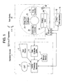
- Figure 1 is a configuration diagram showing an X-ray CT apparatus 100 in accordance with Example 1.
- the X-ray CT apparatus 100 comprises an operation console 1, a table apparatus 10, and a scan gantry 20.
- the operation console 1 comprises an input device 2 for accepting inputs by a human operator, a central processing apparatus 3 for executing data collection processing, data correction processing, image reconstruction processing, and the like, a data collection buffer 5 for collecting data acquired at the scan gantry 20, a CRT 6 for displaying a CT image reconstructed from the data, and a storage device 7 for storing programs, data, and X-ray CT images.
- the table apparatus 10 comprises a table 12 for laying thereon a subject to be imaged and transporting the subject into/out of a bore (cavity portion) of the scan gantry 20.
- the table 12 is vertically and horizontally/rectilinearly moved by a motor incorporated in the table apparatus 10.
- the scan gantry 20 comprises an X-ray tube 21, an X-ray controller 22, a collimator 23, a detector 24, a DAS (data acquisition system) 25, a rotator-side controller 26 for controlling the X-ray controller 22, collimator 23 and DAS 25, an overall controller 29 for communicating control signals etc. with the operation console 1 and imaging table 10, and a slip ring 30.
- the detector 24 may be a single-row detector.
- Figure 2 is a flow chart showing the general operation of the X-ray CT apparatus 100.
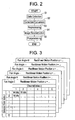
- Step S1 data D( z , r , ⁇ , c ) represented by a rectilinear motion position z, a detector row index r , a fan angle ⁇ , and a channel index c are collected while rotating the X-ray tube 21 and detector 24 around the subject to be imaged.
- Figure 3 shows the collected data D( z , r , ⁇ , c ).
- the rectilinear motion position z is detected by an encoder in the table apparatus 10, and it is constant in an axial scan while it varies in a helical scan. An axial scan is assumed here.
- Step S2 the collected data set is subjected to data correction processing in the detector row direction ( Figure 4) and data correction processing in the channel direction ( Figure 7), which will be described in detail later, and then to fan-parallel conversion.
- Step S3 the data set is subjected to pre-processing (offset correction, log correction, X-ray dose correction, sensitivity correction, etc.).
- Step S4 the data set is subjected to image reconstruction to produce a CT image.
- Step S5 the produced CT image is subjected to post-processing for display.
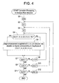
- Figure 4 is a flow chart showing details of data correction processing in the detector row direction.
- Step Q4 if the difference between data D( r , ⁇ , c ) of interest and data D( r +1, ⁇ , c ) at a detector row adjacent to the detector row corresponding to the data D( r , ⁇ , c ) is greater than a threshold Kr (empirically determined), the process goes to Step Q5; otherwise to Step Q7.
- a threshold Kr empirically determined
- edge enhancement is applied to the data D( r , ⁇ , c ) of interest in the detector row direction so that the degree of enhancement is increased for a larger difference between the data D( r , ⁇ , c ) of interest and the data D( r +1, ⁇ , c ) at a detector row adjacent to the detector row corresponding to the data D( r , ⁇ , c ).
- the process then goes to Step Q7.
- Step Q7 if the detector row index r is not r ⁇ R - 1, the process goes to Step Q8; otherwise, goes to Step Q9.
- Step Q8 the detector row index r is incremented by one, and the process goes back to Step Q4.
- Step Q9 if the channel index c is not c ⁇ C, the process goes to Step Q10; otherwise, goes to Step Q11.
- Step Q10 the channel index c is incremented by one, and the process goes back to Step Q3.
- Step Q11 if the fan angle ⁇ is not ⁇ ⁇ ⁇ the process goes to Step Q12; otherwise, the process is terminated.
- Step Q12 the fan angle ⁇ is incremented by ⁇ , and the process goes back to Step Q2.
- Figure 7 is a flow chart showing details of data correction processing in the channel direction.
- Step H4 if the difference between data D( r , ⁇ , c ) of interest and data D( r , ⁇ , c +1) at a channel adjacent to the channel corresponding to the data D( r , ⁇ , c ) is smaller than a threshold Kc (empirically determined), the process goes to Step H6; otherwise to Step H7.
- a threshold Kc empirically determined
- Step H6 smoothing is applied to the data D( r , ⁇ , c ) of interest in the channel direction so that the degree of smoothing is increased for a smaller difference between the data D( r , ⁇ , c ) of interest and the data D( r , ⁇ , c +1) at a channel adjacent to the channel corresponding to the data D( r , ⁇ , c ).
- the process then goes to Step H7.
- Step H7 if the channel index c is not c ⁇ C - 1, the process goes to Step H8; otherwise, goes to Step H9.
- Step H8 the channel index c is incremented by one, and the process goes back to Step H4.
- Step H9 if the detector row index r is not r ⁇ R, the process goes to Step H10; otherwise, to Step H11.
- Step H10 the detector row index r is incremented by one, and the process goes back to Step H3.
- Step H11 if the fan angle ⁇ is not ⁇ ⁇ ⁇ , the process goes to Step H12; otherwise, the process is terminated.
- Step H12 the fan angle ⁇ is incremented by ⁇ , and the process goes back to Step H2.
- edge enhancement is applied when the shape of the subject to be imaged is complex in the detector row direction, thereby improving spatial resolution.
- no edge enhancement is applied when the shape of the subject to be imaged is simple in the detector row direction, thus preventing exaggeration of noise.
- smoothing is applied when the shape of the subject to be imaged is simple in the channel direction, noise can be suppressed.
- no smoothing is applied when the shape of the subject to be imaged is complex in the channel direction, preventing degeneration of spatial resolution.
- Example 2 the data set collected at Step S1 in Figure 2 is subjected to fan-parallel conversion at Step S2, and then to data correction processing in the view direction ( Figure 11) and data correction processing in the channel direction ( Figure 14).
- Figure 10 shows a data set after fan-parallel conversion.
- Figure 11 is a flow chart showing details of data correction processing in the detector row direction.
- Step P4 if the difference between data D( r , v , c ) of interest and data D( r , v +1, c ) at a view adjacent to the view corresponding to the data D( r , v , c) is greater than a threshold Kv (empirically determined), the process goes to Step P5; otherwise to Step P6.
- a threshold Kv empirically determined
- Step P5 edge enhancement is applied to the data D( r, v, c ) of interest in the view direction. The process then goes to Step P7.
- Step P6 smoothing is applied to the data D( r, v, c ) of interest in the view direction. The process then goes to Step P7.
- Step P7 if the view index v is not v ⁇ V - 1, the process goes to Step P8; otherwise, to Step P9.
- Step P8 the view index v is incremented by one, and the process goes back to Step P4.
- Step P9 if the channel index c is not c ⁇ C, the process goes to Step P10; otherwise, to Step P11.
- Step P10 the channel index c is incremented by one, and the process goes back to Step P3.
- Step P11 if the detector row index r is not r ⁇ R, the process goes to Step P12; otherwise, the process is terminated.
- Step P12 the detector row index r is incremented by one, and the process goes back to Step P2.
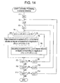
- Figure 14 is a flow chart showing details of data correction processing in the channel direction.
- Step F4 if the difference between data D( r , v, c ) of interest and data D( r, v, c +1) of a channel adjacent to the channel corresponding to the data D( r, v, c ) is greater than a threshold Kc (empirically determined), the process goes to Step F5; otherwise, to Step F6.
- a threshold Kc empirically determined
- Step F5 edge enhancement is applied to the data D( r, v, c ) of interest in the view direction so that the degree of enhancement is increased for a larger difference between the data D( r, v, c ) of interest and the data D( r, v, c +1) at a view adjacent to the view corresponding to the data D( r, v, c ).
- Step F7 edge enhancement is applied to the data D( r, v, c ) of interest in the view direction so that the degree of enhancement is increased for a larger difference between the data D( r, v, c ) of interest and the data D( r, v, c +1) at a view adjacent to the view corresponding to the data D( r, v, c ).
- Step F6 smoothing is applied to the data D( r, v, c ) of interest in the channel direction so that the degree of smoothing is increased for a smaller difference between the data D( r, v, c ) of interest and the data D( r, v, c +1) at a channel adjacent to the channel corresponding to the data D( r, v, c ).
- the process then goes to Step F7.
- Step F7 if the channel index c is not c ⁇ C - 1, the process goes to Step F8; otherwise, to Step F9.
- Step F8 the channel index c is incremented by one, and the process goes back to Step F4.
- Step F9 if the view index v is not v ⁇ V, the process goes to Step F10; otherwise, to Step F11.
- Step F10 the view index v is incremented by one, and the process goes back to Step F3.
- Step F11 if the detector row index r is not r ⁇ R, the process goes to Step F12; otherwise, the process is terminated.
- Step F12 the detector row index r is incremented by one, and the process goes back to Step F2.
- edge enhancement is applied when the shape of the subject to be imaged is complex in the view direction, thereby improving spatial resolution.
- smoothing is applied when the shape of the subject to be imaged is simple in the view direction, noise can be suppressed.
- edge enhancement is applied when the shape of the subject to be imaged is complex in the channel direction, thereby improving spatial resolution.
- smoothing is applied when the shape of the subject to be imaged is simple in the channel direction, noise can be suppressed.
Landscapes
- Engineering & Computer Science (AREA)
- Physics & Mathematics (AREA)
- General Physics & Mathematics (AREA)
- Theoretical Computer Science (AREA)
- Health & Medical Sciences (AREA)
- Life Sciences & Earth Sciences (AREA)
- Medical Informatics (AREA)
- Radiology & Medical Imaging (AREA)
- Surgery (AREA)
- Nuclear Medicine, Radiotherapy & Molecular Imaging (AREA)
- Optics & Photonics (AREA)
- Pathology (AREA)
- Biophysics (AREA)
- Biomedical Technology (AREA)
- Heart & Thoracic Surgery (AREA)
- Molecular Biology (AREA)
- High Energy & Nuclear Physics (AREA)
- Animal Behavior & Ethology (AREA)
- General Health & Medical Sciences (AREA)
- Public Health (AREA)
- Veterinary Medicine (AREA)
- Apparatus For Radiation Diagnosis (AREA)
- Analysing Materials By The Use Of Radiation (AREA)
- Image Processing (AREA)
Applications Claiming Priority (2)
| Application Number | Priority Date | Filing Date | Title |
|---|---|---|---|
| JP2003419384A JP2005176988A (ja) | 2003-12-17 | 2003-12-17 | データ補正方法およびx線ct装置 |
| JP2003419384 | 2003-12-17 |
Publications (2)
| Publication Number | Publication Date |
|---|---|
| EP1544798A2 true EP1544798A2 (de) | 2005-06-22 |
| EP1544798A3 EP1544798A3 (de) | 2010-07-28 |
Family
ID=34510637
Family Applications (1)
| Application Number | Title | Priority Date | Filing Date |
|---|---|---|---|
| EP04257644A Withdrawn EP1544798A3 (de) | 2003-12-17 | 2004-12-09 | Verfahren zur Korrektur von Daten und Röntgen-Tomographiegerät |
Country Status (5)
| Country | Link |
|---|---|
| US (1) | US7406188B2 (de) |
| EP (1) | EP1544798A3 (de) |
| JP (1) | JP2005176988A (de) |
| KR (1) | KR100685560B1 (de) |
| CN (1) | CN1628612A (de) |
Cited By (1)
| Publication number | Priority date | Publication date | Assignee | Title |
|---|---|---|---|---|
| GB2413471A (en) * | 2002-03-27 | 2005-10-26 | Agilent Technologies Inc | Tomography of a curved surface with correction for expected distortion. |
Families Citing this family (2)
| Publication number | Priority date | Publication date | Assignee | Title |
|---|---|---|---|---|
| JP4607476B2 (ja) * | 2004-03-10 | 2011-01-05 | 株式会社東芝 | 放射線画像診断装置および放射線画像診断装置のデータ処理方法 |
| JP2008220653A (ja) * | 2007-03-13 | 2008-09-25 | Toshiba Corp | X線ct装置、被検体外形推定方法、画像再構成方法 |
Family Cites Families (17)
| Publication number | Priority date | Publication date | Assignee | Title |
|---|---|---|---|---|
| US4670840A (en) * | 1983-03-09 | 1987-06-02 | Elscint, Inc. | Ring artifact correction for computerized tomography |
| JP3408848B2 (ja) * | 1993-11-02 | 2003-05-19 | 株式会社日立メディコ | 散乱x線補正法及びx線ct装置並びに多チャンネルx線検出器 |
| US5533081A (en) | 1995-01-17 | 1996-07-02 | General Electric Company | Guided ringfix algorithm for image reconstruction |
| US5933540A (en) | 1995-05-11 | 1999-08-03 | General Electric Company | Filter system and method for efficiently suppressing noise and improving edge definition in a digitized image |
| IL119283A0 (en) | 1996-09-19 | 1996-12-05 | Elscint Ltd | Adaptive filtering |
| US6028909A (en) * | 1998-02-18 | 2000-02-22 | Kabushiki Kaisha Toshiba | Method and system for the correction of artifacts in computed tomography images |
| US6208763B1 (en) | 1998-04-14 | 2001-03-27 | General Electric Company | Method and apparatus for enhancing discrete pixel images |
| JP4213785B2 (ja) | 1998-06-19 | 2009-01-21 | 株式会社日立メディコ | X線ct装置 |
| US6556720B1 (en) * | 1999-05-24 | 2003-04-29 | Ge Medical Systems Global Technology Company Llc | Method and apparatus for enhancing and correcting digital images |
| US6693669B1 (en) | 2000-06-16 | 2004-02-17 | Motorola, Inc. | Method for reducing image blurring |
| JP4703029B2 (ja) | 2001-05-14 | 2011-06-15 | 三菱電機株式会社 | 画像表示システム及び画像表示方法 |
| US6801646B1 (en) | 2001-07-19 | 2004-10-05 | Virtualscopics, Llc | System and method for reducing or eliminating streak artifacts and illumination inhomogeneity in CT imaging |
| DE10141344A1 (de) * | 2001-08-23 | 2003-03-20 | Siemens Ag | Verfahren zur Erzeugung von Bildern aus computertomographischen Messdaten |
| DE10155089C1 (de) * | 2001-11-09 | 2003-06-18 | Siemens Ag | Verfahren zur Entfernung von Ringen und Teilringen in Computertomographie-Bildern |
| JP2003274180A (ja) | 2002-03-12 | 2003-09-26 | Canon Inc | 画像処理装置、画像処理方法、プリンタドライバ、コンピュータ読み取り可能な記憶媒体及びコンピュータプログラム |
| US6625249B1 (en) * | 2002-09-20 | 2003-09-23 | General Electric Company | Method, system and program product for tomographic backprojection using multi-color rendering engine |
| CN1238505C (zh) | 2002-12-05 | 2006-01-25 | 国家饲料质量监督检验中心(北京) | 与β-受体激动剂类药物特异结合的受体蛋白及其编码基因与应用 |
-
2003
- 2003-12-17 JP JP2003419384A patent/JP2005176988A/ja active Pending
-
2004
- 2004-12-09 EP EP04257644A patent/EP1544798A3/de not_active Withdrawn
- 2004-12-15 US US11/013,216 patent/US7406188B2/en not_active Expired - Fee Related
- 2004-12-16 CN CNA200410101164XA patent/CN1628612A/zh active Pending
- 2004-12-16 KR KR1020040106725A patent/KR100685560B1/ko not_active Expired - Fee Related
Cited By (2)
| Publication number | Priority date | Publication date | Assignee | Title |
|---|---|---|---|---|
| GB2413471A (en) * | 2002-03-27 | 2005-10-26 | Agilent Technologies Inc | Tomography of a curved surface with correction for expected distortion. |
| GB2413471B (en) * | 2002-03-27 | 2006-04-19 | Agilent Technologies Inc | Tomography of curved surfaces |
Also Published As
| Publication number | Publication date |
|---|---|
| US7406188B2 (en) | 2008-07-29 |
| US20050135556A1 (en) | 2005-06-23 |
| CN1628612A (zh) | 2005-06-22 |
| EP1544798A3 (de) | 2010-07-28 |
| KR20050061348A (ko) | 2005-06-22 |
| KR100685560B1 (ko) | 2007-02-22 |
| JP2005176988A (ja) | 2005-07-07 |
Similar Documents
| Publication | Publication Date | Title |
|---|---|---|
| US10013779B2 (en) | Metal artifact reduction for 3D-digtial subtraction angiography | |
| US8280135B2 (en) | System and method for highly attenuating material artifact reduction in x-ray computed tomography | |
| US7466790B2 (en) | Systems and methods for improving a resolution of an image | |
| EP1741062B1 (de) | Conus-strahl-ct-vorrichtung mit abgeschnittenen projektionen und einem zuvor erfassten 3d-ct-bild | |
| US6035012A (en) | Artifact correction for highly attenuating objects | |
| US5727041A (en) | Methods and apparatus for reducing partial volume image artifacts | |
| US5864598A (en) | Methods and apparatus for scanning an object in a computed tomography system | |
| US8401266B2 (en) | Method and system for correlated noise suppression in dual energy imaging | |
| JP4576032B2 (ja) | 2回パス式コーン・ビーム画像再構成の方法及び装置 | |
| IL100312A (en) | Method and apparatus for reconstructing a three-dimensional computerized tomography (ct) image of an object from incomplete cone beam projection data | |
| US8750582B2 (en) | Method for recording and reconstructing a three-dimensional image dataset and X-ray apparatus | |
| WO2013147843A1 (en) | Projection data binning and image generation in photon counting imaging modality | |
| JP2007307417A (ja) | 像データの処理方法及び像データの処理装置 | |
| US20120019512A1 (en) | Noise suppression for cone-beam image reconstruction | |
| JPH09285460A (ja) | 物体の断層写真画像を発生するシステム | |
| DE19526930A1 (de) | Detektorsignal-Integration von volumetrischen CT Scanner-Detektorarrays | |
| US7215734B2 (en) | Method and system for three-dimensional reconstruction of images | |
| US7747057B2 (en) | Methods and apparatus for BIS correction | |
| US7406188B2 (en) | Data correction method and X-ray CT apparatus | |
| US7260175B2 (en) | CT image producing method and X-ray CT apparatus | |
| US20130163714A9 (en) | Methods and apparatus for ct smoothing to reduce artifacts | |
| JP2007044207A (ja) | 放射線ct撮影方法およびx線ct装置 | |
| US20060257011A1 (en) | Method and system for filtering scan data | |
| US20050123091A1 (en) | Three-dimensional backprojection method and apparatus, and X-ray CT apparatus | |
| US7734079B2 (en) | Methods and apparatus for image reconstruction |
Legal Events
| Date | Code | Title | Description |
|---|---|---|---|
| PUAI | Public reference made under article 153(3) epc to a published international application that has entered the european phase |
Free format text: ORIGINAL CODE: 0009012 |
|
| AK | Designated contracting states |
Kind code of ref document: A2 Designated state(s): AT BE BG CH CY CZ DE DK EE ES FI FR GB GR HU IE IS IT LI LT LU MC NL PL PT RO SE SI SK TR |
|
| AX | Request for extension of the european patent |
Extension state: AL BA HR LV MK YU |
|
| PUAL | Search report despatched |
Free format text: ORIGINAL CODE: 0009013 |
|
| AK | Designated contracting states |
Kind code of ref document: A3 Designated state(s): AT BE BG CH CY CZ DE DK EE ES FI FR GB GR HU IE IS IT LI LT LU MC NL PL PT RO SE SI SK TR |
|
| AX | Request for extension of the european patent |
Extension state: AL BA HR LV MK YU |
|
| RIC1 | Information provided on ipc code assigned before grant |
Ipc: G06T 5/00 20060101ALI20100623BHEP Ipc: G06T 11/00 20060101AFI20050405BHEP |
|
| AKY | No designation fees paid | ||
| REG | Reference to a national code |
Ref country code: DE Ref legal event code: R108 Effective date: 20110309 Ref country code: DE Ref legal event code: 8566 |
|
| STAA | Information on the status of an ep patent application or granted ep patent |
Free format text: STATUS: THE APPLICATION IS DEEMED TO BE WITHDRAWN |
|
| 18D | Application deemed to be withdrawn |
Effective date: 20110129 |