EP1544696B1 - Tragbares elektronisches Gerät, das mit einem Drucksensor ausgerüstet ist - Google Patents
Tragbares elektronisches Gerät, das mit einem Drucksensor ausgerüstet ist Download PDFInfo
- Publication number
- EP1544696B1 EP1544696B1 EP04028968A EP04028968A EP1544696B1 EP 1544696 B1 EP1544696 B1 EP 1544696B1 EP 04028968 A EP04028968 A EP 04028968A EP 04028968 A EP04028968 A EP 04028968A EP 1544696 B1 EP1544696 B1 EP 1544696B1
- Authority
- EP
- European Patent Office
- Prior art keywords
- housing
- cap
- sensor
- wall
- case
- Prior art date
- Legal status (The legal status is an assumption and is not a legal conclusion. Google has not performed a legal analysis and makes no representation as to the accuracy of the status listed.)
- Expired - Lifetime
Links
- 230000001681 protective effect Effects 0.000 claims description 10
- 210000000707 wrist Anatomy 0.000 claims description 8
- 230000005540 biological transmission Effects 0.000 claims description 6
- 239000000758 substrate Substances 0.000 claims description 5
- 238000004891 communication Methods 0.000 claims description 2
- 238000007789 sealing Methods 0.000 claims description 2
- 230000000717 retained effect Effects 0.000 claims 1
- XUIMIQQOPSSXEZ-UHFFFAOYSA-N Silicon Chemical compound [Si] XUIMIQQOPSSXEZ-UHFFFAOYSA-N 0.000 description 7
- 229910052710 silicon Inorganic materials 0.000 description 7
- 239000010703 silicon Substances 0.000 description 7
- 238000010276 construction Methods 0.000 description 6
- 229920002994 synthetic fiber Polymers 0.000 description 5
- 230000000694 effects Effects 0.000 description 3
- 239000011248 coating agent Substances 0.000 description 2
- 238000000576 coating method Methods 0.000 description 2
- 239000002991 molded plastic Substances 0.000 description 2
- 229920001296 polysiloxane Polymers 0.000 description 2
- 230000035939 shock Effects 0.000 description 2
- 230000000007 visual effect Effects 0.000 description 2
- XLYOFNOQVPJJNP-UHFFFAOYSA-N water Substances O XLYOFNOQVPJJNP-UHFFFAOYSA-N 0.000 description 2
- 239000000919 ceramic Substances 0.000 description 1
- 239000004020 conductor Substances 0.000 description 1
- 230000007797 corrosion Effects 0.000 description 1
- 238000005260 corrosion Methods 0.000 description 1
- 229920001971 elastomer Polymers 0.000 description 1
- 239000000806 elastomer Substances 0.000 description 1
- 238000004519 manufacturing process Methods 0.000 description 1
- 239000000463 material Substances 0.000 description 1
- 239000012528 membrane Substances 0.000 description 1
- 230000035515 penetration Effects 0.000 description 1
- 229920003223 poly(pyromellitimide-1,4-diphenyl ether) Polymers 0.000 description 1
- 230000002035 prolonged effect Effects 0.000 description 1
- 239000004576 sand Substances 0.000 description 1
- 239000013535 sea water Substances 0.000 description 1
- 229920002050 silicone resin Polymers 0.000 description 1
- 229920002379 silicone rubber Polymers 0.000 description 1
- 239000007787 solid Substances 0.000 description 1
- 239000000725 suspension Substances 0.000 description 1
- 238000003466 welding Methods 0.000 description 1
Images


Classifications
-
- G—PHYSICS
- G04—HOROLOGY
- G04G—ELECTRONIC TIME-PIECES
- G04G21/00—Input or output devices integrated in time-pieces
- G04G21/02—Detectors of external physical values, e.g. temperature
-
- G—PHYSICS
- G04—HOROLOGY
- G04B—MECHANICALLY-DRIVEN CLOCKS OR WATCHES; MECHANICAL PARTS OF CLOCKS OR WATCHES IN GENERAL; TIME PIECES USING THE POSITION OF THE SUN, MOON OR STARS
- G04B47/00—Time-pieces combined with other articles which do not interfere with the running or the time-keeping of the time-piece
- G04B47/06—Time-pieces combined with other articles which do not interfere with the running or the time-keeping of the time-piece with attached measuring instruments, e.g. pedometer, barometer, thermometer or compass
- G04B47/066—Time-pieces combined with other articles which do not interfere with the running or the time-keeping of the time-piece with attached measuring instruments, e.g. pedometer, barometer, thermometer or compass with a pressure sensor
-
- B—PERFORMING OPERATIONS; TRANSPORTING
- B63—SHIPS OR OTHER WATERBORNE VESSELS; RELATED EQUIPMENT
- B63C—LAUNCHING, HAULING-OUT, OR DRY-DOCKING OF VESSELS; LIFE-SAVING IN WATER; EQUIPMENT FOR DWELLING OR WORKING UNDER WATER; MEANS FOR SALVAGING OR SEARCHING FOR UNDERWATER OBJECTS
- B63C11/00—Equipment for dwelling or working underwater; Means for searching for underwater objects
- B63C11/02—Divers' equipment
Definitions
- the present invention relates to a portable electronic wrist device, including a plunger wristwatch, a bathymeter or altimeter, having a housing and a pressure sensor which is mounted in a housing housing and has an exposed surface therein the housing for receiving the ambient pressure, said housing opening on an outer face of the housing and being closed on this face by a cover having an outer wall provided with at least one orifice in front of the housing for transmitting the ambient pressure from outside the housing; housing towards the housing.
- the housing of the pressure sensor is provided in a lateral protuberance of the housing and opens on the upper face of this housing, so that one can implement the sensor from the top.
- the pressure sensor comprises a silicon piezoresistive element which is housed in a pot-shaped structure and coated with a silicone gel in order to be protected from the effects of water. .
- This gel is further covered with a flexible layer of silicone resin or rubber, which forms the exposed surface of the sensor and transmits the ambient pressure to the piezoresistive element.
- the hood closing the housing is formed by a perforated circular plate. The orifices of this plate are arranged along its periphery, so as not to be in front of the silicon element and the coating gel thereof. This arrangement is intended to prevent foreign bodies engaging in these holes can damage the silicon element or gel.
- Portable electronic devices are also known wrist as described in EP 1006418 or in JP 2002 323581 .
- the present invention aims to overcome the aforementioned drawbacks of the prior art, thanks to a particularly simple and effective arrangement of sensor mounting members in the housing which is intended for it.
- a particular object is to design these members so as to simplify to a large extent the mounting of the sensor and associated components of the apparatus, particularly for automated mounting.
- the invention relates to a portable electronic device as defined in claim 1.
- the shield provided in this invention provides a double protection of the sensor, that is to say against the solid bodies and against light, and this with a construction that can be extremely simple and compact, for example with the addition of a plate having perforations judiciously disposed under the hood closing the housing of the pressure sensor.
- this construction advantageously makes it possible to place the outer orifice (s) of the hood in front of the exposed surface of the sensor, thus in the central region of the hood, which makes it possible to reduce the external dimensions and the visual impact of the hood.
- the side of the housing having the housing for the sensor can be both a side face and the upper face of the housing.
- the protective screen may be formed by a perforated plate extending substantially parallel to said wall of the cover, the holes of the perforated plate being offset laterally with respect to each orifice of the cover so that an orthogonal projection or orifice (s) on the perforated plate is spaced from the holes thereof.
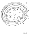
- a wristwatch 1 for a plunger has a case 2 of rigid synthetic material which notably contains an electronic clockwork movement, a pressure sensor sensitive to the ambient pressure prevailing outside the case, analog display elements and and / or digital and electronic circuits for processing the pressure information and displaying results by the display means.
- the casing 2 comprises a middle part 3 of synthetic material, surrounding a central cavity 4 ( figure 4 ) which is closed at the bottom by a bottom 5 and at the top by an ice 6 lined with a bezel 7.
- the central cavity 4 contains the main components of the plunger watch, in particular the printed circuit board 8 which carries the main circuits electronic watch.
- the pressure sensor 10 is placed in a housing 11 formed in the middle part 3 and opening on the left outer face 9 of the housing 2, so that the sensor can be mounted in this housing from the outside of the housing.
- the sensor 10 is held in this housing using two elements shown in FIG. figure 2 , namely an O-ring seal 12 and a cover 13, and is further protected by a screen here formed of a perforated plate 14 mounted inside the cover 13.
- the surface of the hood 13 is preferably, but not necessarily, flush with the lateral outer face 9 of the housing. This face is never in contact with the wrist 15 of the wearer when the wristwatch is worn, so that the ambient pressure reaches the surface of the hood without restraint, whether in the air or in the water.
- the pressure sensor 10 is of known construction. It comprises a silicon piezoresistive element 16 mounted on a square ceramic substrate 17 provided with conductors which connect the element 16 to contact pads disposed on the back of the substrate. These pads make contact with a printed circuit film 18 applied behind the substrate 17.
- the sensor 10 further comprises a cylindrical side wall 20 which is fixed on the front face of the substrate 17 and forms with it a pot-shaped structure which surrounds the silicon element 16, which is encapsulated by a silicone gel 21 whose front surface 22 constitutes the exposed surface of the sensor, intended to receive the ambient pressure.
- the housing 11 provided for the sensor in the middle of the housing has a flat and substantially square bottom wall 24 against which the sensor structure and the printed circuit film 18 are supported, and in which a window 25 is provided. communicating the housing 11 with the central cavity 4.
- the housing 11 is delimited laterally by a circular projecting wall 26 having a discontinuous radial rim 27 on its outer surface. This flange extends into a groove 28 which surrounds the wall 26 over its entire circumference, except in a sector provided with a blind guide hole 29.
- the elastomer seal 12 is placed around the side wall 20 of the sensor and is compressed radially between this wall and the protruding wall 26 of the housing 11. It thus ensures not only the seal, but also an elastic suspension protecting the sensor against shock that could suffer the housing.
- the cover 13 is preferably a molded piece of synthetic material opaque or provided with an opaque coating. It comprises in its central region an outer wall 31 in the form of a circular plate of variable thickness, traversed by three orifices 32 which have a diameter of about 1.5 mm in this example. These orifices open outwardly into respective concave surfaces 33, the effect of which is both decorative and functional, to prevent the orifice being easily closed by a flat foreign body.
- the wall 31 of the cover has protruding surfaces 34 and 35 to support the protection plate 14, lateral shoulders 36 to wedge laterally this plate, and three pins 37 whose role will appear later.
- the periphery of the cover 13 comprises a circular rim 38 arranged to catch on the outer rim 27 of the wall 26 of the housing of the sensor, so that the cover 13 can be fixed simply by clipping on the housing 2.
- the cover still has a finger of guide 39 which engages in the hole 29 to ensure the correct orientation of the hood, thus the desired position of its three orifices 32.
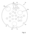
- the figure 6 shows in more detail the configuration of the protective plate 14, which is, in this example, a simple circular plate made of a fairly rigid synthetic material, for example made of Kapton®, but could be made of any rigid material resistant to corrosion, particularly in the presence of seawater.
- the protective plate 14 On its periphery are provided three wedges 40, designed to cooperate with the shoulders 36 of the cover 13, and a locating notch 41 for the mechanized positioning of the plate in the hood.
- the notch 41 can also serve as a visual cue in case of manual placement of the plate.
- Small protruding parts 44 ( figure 5 ) are formed on the inside of the cover to retain the plate 14 by their elasticity.
- the plate 14 is pierced with a plurality of holes 42 to allow the ambient pressure to be transmitted towards the sensor 10.
- a plurality of holes 42 there are provided twenty holes 42 having a diameter of about 0.5 mm. . All these holes are clearly offset laterally with respect to the orifices 32 of the cover 13, orifices whose position projected perpendicularly on the plate 14 is represented in FIG. figure 6 by three circles 32a.
- the holes 42 are distributed on the plate 14 in such a way that none of them is less than 0.75 mm from one of the circles 32a. It will be noted that three of the holes 42 are arranged to be traversed by the pins 37 of the cover, which can abut against the end face of the cylindrical wall 20 of the sensor 10 to retain it in its housing.
- the protection plate 14, once it is placed inside the cover 13, is at a constant distance of about 0.1 mm from the wall 31 of the cover.
- the ambient pressure outside the housing 2 is transmitted to the exposed surface 22 of the sensor 10 through the openings 32 of the hood, then following for a distance the gap of 0.1 mm between the plates 14 and 31, and finally through the holes 42 of the plate 14 to reach the housing 11 of the sensor.
- any transmission path from the ambient pressure to the exposed surface 22 of the sensor is highly sinuous. On the one hand, this avoids any risk of damaging the sensor by intrusion of foreign bodies, especially since the gap between the two plates is very small.
- the thickness of this gap is less than 0.2 mm in order to prevent the penetration of foreign bodies such as grains of sand.
- the protection plate 14 is a screen both very efficient and very simple to manufacture and mount, preventing the intrusion of foreign bodies and ambient light to the sensor.
- a notable advantage of this type of screen is to allow to place the orifices 32 of the cover 13 in front of the exposed surface 22 of the sensor, even in the center of the cover, which makes it possible to reduce to a minimum the external dimensions of the screen. hood, its diameter in this case.
- This aspect is particularly advantageous when the present invention is applied to a wristwatch, because it allows to place the pressure sensor in a discrete manner in a sidewall of the case without harming the overall appearance of the watch.
- the flexible blades 46 extend through the window 25 and apply their elasticity against contact pads provided on the printed circuit 18 backed to the sensor 10, which ensures good transmission of electrical signals output from the sensor itself if it moves slightly under the effect of a shock.
- the main advantage of this arrangement is to facilitate the assembly of the components of the watch. For example, one can mount the pressure sensor 10 in the middle part 3 of the housing and fix it by means of the cover 13, before starting the general assembly of the watch and in particular the mounting of its components in its central cavity 4. During assembly, it is then possible to place in this cavity the pre-assembled electronic module on the card 8, so that the flexible contact blades 46 will automatically establish a correct electrical contact with the sensor 10.
- the protective screen described above with reference to the drawings is formed by adding a simple perforated plate, it could be achieved otherwise without departing from the scope of the invention defined by the claims.
- the shield could comprise two perforated plates parallel and spaced from each other, the respective holes of the plates being offset laterally between them so that an orthogonal projection of the holes of one of the plates on the plate. other plate is spaced from the holes in it.
- the protective screen could comprise a flat element thicker than a simple plate and containing in its thickness a plurality of channels extending in its median plane and whose ends would open respectively on both sides of this plate. element. Such an element can be easily made by assembling two molded plastic plates, the channels being formed on one side of one of the plates.
- the applications of the invention are not limited to the example described above, but extend to any portable electronic device comprising a pressure sensor mounted in a housing which opens onto an outer face of the housing of the apparatus, for example an altimeter or a dive computer.
Landscapes
- Physics & Mathematics (AREA)
- General Physics & Mathematics (AREA)
- Electric Clocks (AREA)
- Measuring Fluid Pressure (AREA)
Claims (8)
- Elektronisches, am Handgelenk tragbares Gerät, insbesondere eine Armbanduhr, umfassend ein Gehäuse (2) und einen Drucksensor (10), der in einer Lagerung (11) des Gehäuses montiert ist, und eine ausgesetzte Fläche (22) im Inneren der Lagerung aufweist, um den Umgebungsdruck zu messen, wobei die besagte Lagerung auf einer äusseren Stirnfläche des Gehäuses mündet, und auf dieser Stirnfläche von einer Haube (13) geschlossen ist, die eine externe mit wenigstens einer Öffnung vor der Lagerung versehenen Wand (31) aufweist, um den Umgebungsdruck vom Aussen des Gehäuses zu der Lagerung zu übertragen,
wobei die besagte äussere Stirnfläche (9) des Gehäuses sich auf einer Seite des Gehäuses befindet, die nicht im Kontakt mit dem Handgelenk des Trägers treten kann, und wobei wenigstens eine Abschirmung (14) in der Lagerung (11) hinter der Öffnung oder den Öffnungen (32) der Haube derart angeordnet ist, dass jede gerade Verbindung zwischen den Öffnungen (32) der Haube und der ausgesetzten Fläche (22) des Drucksensors (10) verhindert ist, so dass jede Drucksübertragungsweg des Umgebungsdrucks zu der ausgesetzten Fläche (22) kurvig ist, dadurch gekennzeichnet, dass die Abschirmung eine durchlöcherte Platte (14) umfasst, die mit einer Vielzahl von Löchern (42) gebohrt ist, wobei die Löcher (42) der durchlöcherte Platte derart im Vergleich zu den Öffnungen (32) der Haube versetzt sind, dass eine orthogonale Projektion (32a) der Öffnung oder der Öffnungen (32) auf die durchlöcherten Platte mit einem Abstand von wenigstens 0.75 mm von dessen Löchern entfernt ist. - Gerät gemäss Anspruch 1, dadurch gekennzeichnet, dass die Abschirmung (14) zwei parallele durchlöcherte Platten aufweist, die voneinander getrennt sind, wobei die Löcher der jeweiligen Platten derart versetzt sind, dass eine orthogonale Projektion der Öffnungen einer der durchlöcherten Platte von den Öffnungen der anderen durchlöcherten Platte entfernt ist.
- Gerät gemäss Anspruch 1 order 2, dadurch gekennzeichnet, dass die Abschirmung (14) auf einer inneren Seite der Haube (13) montiert ist, und auf deren äusserem Rand Nuten (40) aufweist, die derart angeordnet sind, dass sie auf Positionierungsschulter (36), die Bestandteil der Haube sind, einfügen.
- Gerät gemäss Anspruch 1 order 2, dadurch gekennzeichnet, dass der Abstand zwischen der Abschirmung (14) und der besagten externen Wand (31) sich auf weniger als 0.2 mm beträgt.
- Gerät gemäss einem der vorigen Ansprüche, dadurch gekennzeichnet, dass wenigstens eine der Öffnungen (32) der Haube sich in einer zentralen Region der Haube, gegenüber der ausgesetzten Fläche (22) des Drucksensors, befindet.
- Gerät gemäss einem der vorigen Ansprüche, dadurch gekennzeichnet, dass der Drucksensor (10) eine Topfförmige Struktur umfasst, die einen im wesentlichen flachen Substrat (17) und eine zylindrische laterale Wand (20) aufweist, die die besagte ausgesetzte Fläche des Sensors umringt; dass die Lagerung (11) von einer kreisförmigen vorspringenden Wand (26) abgegrenzt ist, wobei eine O-rind Dichtung (12) zwischen der vorspringenden Wand und der zylindrischen lateralen Wand des Sensors komprimiert ist, und dass die Haube (13) die besagte vorspringende Wand (26) des Sensors auf der äusseren Seite des Gehäuses bedeckt, und derart angeordnet ist, um auf dieser Wand anzuhängen.
- Gerät gemäss Anspruch 6, dadurch gekennzeichnet, dass die Struktur des Sensors (10) in der Lagerung (11) von ihren zylindrischen lateralen Wand (20) einbehaltet ist, die gegen die Haube (13) oder die Abschirmung (14) abschlägt.
- Gerät gemäss einem der vorigen Ansprüche, dadurch gekenntzeichnet, dass die Lagerung (11) von einer zentralen Aushöhlung (4) des Gehäuses von einer Bodenwand (24) getrennt ist, die ein Fenster (25) für den Durchgang flexibler Kontaktklingen (46) eines in der zentralen Aushöhlung angeordneten elektronischen Modul aufweist, wobei die besagten Kontaktklingen sich gegen den mit dem Drucksensor verbundenen Kontakten (10) aufstützen.
Priority Applications (1)
| Application Number | Priority Date | Filing Date | Title |
|---|---|---|---|
| EP04028968A EP1544696B1 (de) | 2003-12-17 | 2004-12-07 | Tragbares elektronisches Gerät, das mit einem Drucksensor ausgerüstet ist |
Applications Claiming Priority (3)
| Application Number | Priority Date | Filing Date | Title |
|---|---|---|---|
| EP03028955 | 2003-12-17 | ||
| EP03028955 | 2003-12-17 | ||
| EP04028968A EP1544696B1 (de) | 2003-12-17 | 2004-12-07 | Tragbares elektronisches Gerät, das mit einem Drucksensor ausgerüstet ist |
Publications (3)
| Publication Number | Publication Date |
|---|---|
| EP1544696A2 EP1544696A2 (de) | 2005-06-22 |
| EP1544696A3 EP1544696A3 (de) | 2009-06-24 |
| EP1544696B1 true EP1544696B1 (de) | 2011-11-09 |
Family
ID=34524723
Family Applications (1)
| Application Number | Title | Priority Date | Filing Date |
|---|---|---|---|
| EP04028968A Expired - Lifetime EP1544696B1 (de) | 2003-12-17 | 2004-12-07 | Tragbares elektronisches Gerät, das mit einem Drucksensor ausgerüstet ist |
Country Status (1)
| Country | Link |
|---|---|
| EP (1) | EP1544696B1 (de) |
Cited By (1)
| Publication number | Priority date | Publication date | Assignee | Title |
|---|---|---|---|---|
| EP2770380A1 (de) | 2013-02-21 | 2014-08-27 | The Swatch Group Research and Development Ltd. | Elektronische Vorrichtung, die mit Mitteln zur automatischen Erkennung eines Lecks ausgestattet ist |
Families Citing this family (5)
| Publication number | Priority date | Publication date | Assignee | Title |
|---|---|---|---|---|
| EP1672443B1 (de) * | 2004-12-17 | 2010-08-18 | ETA SA Manufacture Horlogère Suisse | Uhr mit einem Drucksensor |
| EP3032266A1 (de) * | 2014-12-08 | 2016-06-15 | Breva Genève SA | Uhr, die ein windmessermodul umfasst |
| EP3182221A1 (de) | 2015-12-15 | 2017-06-21 | Omega SA | Uhrenarmband |
| EP3182222A1 (de) * | 2015-12-15 | 2017-06-21 | Omega SA | Uhrenarmband |
| CN116818178B (zh) * | 2023-08-25 | 2023-11-17 | 深圳市微克科技有限公司 | 一种基于智能手表的水深与水压监测方法、系统及介质 |
Family Cites Families (7)
| Publication number | Priority date | Publication date | Assignee | Title |
|---|---|---|---|---|
| US3198013A (en) * | 1961-10-05 | 1965-08-03 | Pechiney | Pressure gage |
| EP0195636B1 (de) * | 1985-03-19 | 1991-07-10 | Citizen Watch Co. Ltd. | Armbanduhr mit Druckmessfühler |
| WO1992001248A1 (fr) * | 1990-07-03 | 1992-01-23 | Citizen Watch Co., Ltd. | Montre avec capteur |
| JP3653746B2 (ja) * | 1993-07-01 | 2005-06-02 | セイコーエプソン株式会社 | 電子時計 |
| DE69518569T2 (de) * | 1994-04-14 | 2001-01-04 | Citizen Watch Co., Ltd. | Uhr mit Detektor |
| US6278659B1 (en) * | 1998-06-22 | 2001-08-21 | Seiko Epson Corporation | Sensor mounting structure and electronics and watch having the structure |
| JP2002323581A (ja) * | 2001-04-27 | 2002-11-08 | Nippon Seiki Co Ltd | センサ付き電子腕時計 |
-
2004
- 2004-12-07 EP EP04028968A patent/EP1544696B1/de not_active Expired - Lifetime
Cited By (1)
| Publication number | Priority date | Publication date | Assignee | Title |
|---|---|---|---|---|
| EP2770380A1 (de) | 2013-02-21 | 2014-08-27 | The Swatch Group Research and Development Ltd. | Elektronische Vorrichtung, die mit Mitteln zur automatischen Erkennung eines Lecks ausgestattet ist |
Also Published As
| Publication number | Publication date |
|---|---|
| EP1544696A3 (de) | 2009-06-24 |
| EP1544696A2 (de) | 2005-06-22 |
Similar Documents
| Publication | Publication Date | Title |
|---|---|---|
| EP1672443B1 (de) | Uhr mit einem Drucksensor | |
| EP2859412B1 (de) | System eines drehbaren aussenrings (einer uhr) | |
| KR101077436B1 (ko) | 압력센서를 포함한 휴대용 전자장치 | |
| EP1662342A1 (de) | Uhr mit verwechselbarer Lunette | |
| EP0710900B1 (de) | Uhr mit einer in einem metallischen Gehäuse montierten wasserdichten Schale | |
| CH708631B1 (fr) | Pièce d'horlogerie comprenant une lunette. | |
| EP1046968A1 (de) | Gegenseitige Befestigung eines Glases,eines Zifferblattes und eines Werkringes für eine Uhr | |
| EP1544696B1 (de) | Tragbares elektronisches Gerät, das mit einem Drucksensor ausgerüstet ist | |
| EP3141969A1 (de) | Verkleidungselement mit integriertem kommunikationsschaltkreis | |
| EP1046967A1 (de) | Verfahren zum Montieren eines Gehäuseringes in einem Uhrengehäuse und dafür verwendbarer Gehäusering | |
| EP0741344B1 (de) | Sicherheitsvorrichtung mit akustischen Alarm | |
| EP0186804B1 (de) | Am Armgelenk zu tragende elektronische Vorrichtung | |
| CA2181482A1 (fr) | Appareil de communication avec protection electrostatique | |
| EP0168010B1 (de) | Uhrengehäuse | |
| EP0072345A1 (de) | Uhrgehäuse | |
| CH696732A5 (fr) | Appareil electronique portable comportant un capteur de pression. | |
| EP1431847B1 (de) | Tragbares elektronisches Gerät, insbesondere Uhr, mit einer Antenne, die aus einer Spule mit grossem Diameter gebildet ist | |
| EP0269872B1 (de) | Uhrengehäuse | |
| EP0545229A1 (de) | Uhrengehäuse mit einer Armbandschliesse | |
| EP0053557A1 (de) | Auslösevorrichtung der "Glasscheibeart" für Sicherheitskästen | |
| EP4006653A1 (de) | Armbanduhrengehäuse, das eine kontrollvorrichtung einer nahfeldkommunikationsvorrichtung umfasst | |
| FR2834865A1 (fr) | Dispositif de detection d'un risque de verglas pour motard, visiere et casque le comportant | |
| EP4006654A1 (de) | Armbanduhrengehäuse, das eine vorrichtung zur nahfeldkommunikation umfasst | |
| FR2865708A1 (fr) | Module de commande d'un ouvrant de vehicule. | |
| EP0064951A1 (de) | Uhrgehäuse |
Legal Events
| Date | Code | Title | Description |
|---|---|---|---|
| PUAI | Public reference made under article 153(3) epc to a published international application that has entered the european phase |
Free format text: ORIGINAL CODE: 0009012 |
|
| AK | Designated contracting states |
Kind code of ref document: A2 Designated state(s): AT BE BG CH CY CZ DE DK EE ES FI FR GB GR HU IE IS IT LI LT LU MC NL PL PT RO SE SI SK TR |
|
| AX | Request for extension of the european patent |
Extension state: AL BA HR LV MK YU |
|
| PUAL | Search report despatched |
Free format text: ORIGINAL CODE: 0009013 |
|
| AK | Designated contracting states |
Kind code of ref document: A3 Designated state(s): AT BE BG CH CY CZ DE DK EE ES FI FR GB GR HU IE IS IT LI LT LU MC NL PL PT RO SE SI SK TR |
|
| AX | Request for extension of the european patent |
Extension state: AL BA HR LV MK YU |
|
| RIC1 | Information provided on ipc code assigned before grant |
Ipc: G01L 19/06 20060101ALI20090518BHEP Ipc: G04G 1/00 20060101AFI20090518BHEP Ipc: G04G 1/04 20060101ALI20090518BHEP Ipc: G04B 47/06 20060101ALI20090518BHEP |
|
| 17P | Request for examination filed |
Effective date: 20091228 |
|
| AKX | Designation fees paid |
Designated state(s): AT BE BG CH CY CZ DE DK EE ES FI FR GB GR HU IE IS IT LI LT LU MC NL PL PT RO SE SI SK TR |
|
| 17Q | First examination report despatched |
Effective date: 20100209 |
|
| GRAP | Despatch of communication of intention to grant a patent |
Free format text: ORIGINAL CODE: EPIDOSNIGR1 |
|
| REG | Reference to a national code |
Ref country code: DE Ref legal event code: R079 Ref document number: 602004035200 Country of ref document: DE Free format text: PREVIOUS MAIN CLASS: G04G0001040000 Ipc: G04G0021020000 |
|
| RIC1 | Information provided on ipc code assigned before grant |
Ipc: G04G 21/02 20100101AFI20110329BHEP Ipc: G01L 19/06 20060101ALI20110329BHEP |
|
| GRAS | Grant fee paid |
Free format text: ORIGINAL CODE: EPIDOSNIGR3 |
|
| GRAA | (expected) grant |
Free format text: ORIGINAL CODE: 0009210 |
|
| AK | Designated contracting states |
Kind code of ref document: B1 Designated state(s): AT BE BG CH CY CZ DE DK EE ES FI FR GB GR HU IE IS IT LI LT LU MC NL PL PT RO SE SI SK TR |
|
| REG | Reference to a national code |
Ref country code: GB Ref legal event code: FG4D Free format text: NOT ENGLISH |
|
| REG | Reference to a national code |
Ref country code: CH Ref legal event code: EP |
|
| REG | Reference to a national code |
Ref country code: CH Ref legal event code: NV Representative=s name: ICB INGENIEURS CONSEILS EN BREVETS SA |
|
| REG | Reference to a national code |
Ref country code: IE Ref legal event code: FG4D Free format text: LANGUAGE OF EP DOCUMENT: FRENCH |
|
| REG | Reference to a national code |
Ref country code: DE Ref legal event code: R096 Ref document number: 602004035200 Country of ref document: DE Effective date: 20120105 |
|
| REG | Reference to a national code |
Ref country code: NL Ref legal event code: VDEP Effective date: 20111109 |
|
| LTIE | Lt: invalidation of european patent or patent extension |
Effective date: 20111109 |
|
| PG25 | Lapsed in a contracting state [announced via postgrant information from national office to epo] |
Ref country code: LT Free format text: LAPSE BECAUSE OF FAILURE TO SUBMIT A TRANSLATION OF THE DESCRIPTION OR TO PAY THE FEE WITHIN THE PRESCRIBED TIME-LIMIT Effective date: 20111109 Ref country code: IS Free format text: LAPSE BECAUSE OF FAILURE TO SUBMIT A TRANSLATION OF THE DESCRIPTION OR TO PAY THE FEE WITHIN THE PRESCRIBED TIME-LIMIT Effective date: 20120309 |
|
| PG25 | Lapsed in a contracting state [announced via postgrant information from national office to epo] |
Ref country code: GR Free format text: LAPSE BECAUSE OF FAILURE TO SUBMIT A TRANSLATION OF THE DESCRIPTION OR TO PAY THE FEE WITHIN THE PRESCRIBED TIME-LIMIT Effective date: 20120210 Ref country code: SE Free format text: LAPSE BECAUSE OF FAILURE TO SUBMIT A TRANSLATION OF THE DESCRIPTION OR TO PAY THE FEE WITHIN THE PRESCRIBED TIME-LIMIT Effective date: 20111109 Ref country code: PL Free format text: LAPSE BECAUSE OF FAILURE TO SUBMIT A TRANSLATION OF THE DESCRIPTION OR TO PAY THE FEE WITHIN THE PRESCRIBED TIME-LIMIT Effective date: 20111109 Ref country code: NL Free format text: LAPSE BECAUSE OF FAILURE TO SUBMIT A TRANSLATION OF THE DESCRIPTION OR TO PAY THE FEE WITHIN THE PRESCRIBED TIME-LIMIT Effective date: 20111109 Ref country code: PT Free format text: LAPSE BECAUSE OF FAILURE TO SUBMIT A TRANSLATION OF THE DESCRIPTION OR TO PAY THE FEE WITHIN THE PRESCRIBED TIME-LIMIT Effective date: 20120309 Ref country code: SI Free format text: LAPSE BECAUSE OF FAILURE TO SUBMIT A TRANSLATION OF THE DESCRIPTION OR TO PAY THE FEE WITHIN THE PRESCRIBED TIME-LIMIT Effective date: 20111109 |
|
| REG | Reference to a national code |
Ref country code: IE Ref legal event code: FD4D |
|
| PG25 | Lapsed in a contracting state [announced via postgrant information from national office to epo] |
Ref country code: CY Free format text: LAPSE BECAUSE OF FAILURE TO SUBMIT A TRANSLATION OF THE DESCRIPTION OR TO PAY THE FEE WITHIN THE PRESCRIBED TIME-LIMIT Effective date: 20111109 |
|
| BERE | Be: lapsed |
Owner name: ETA SA MANUFACTURE HORLOGERE SUISSE Effective date: 20111231 |
|
| PG25 | Lapsed in a contracting state [announced via postgrant information from national office to epo] |
Ref country code: BG Free format text: LAPSE BECAUSE OF FAILURE TO SUBMIT A TRANSLATION OF THE DESCRIPTION OR TO PAY THE FEE WITHIN THE PRESCRIBED TIME-LIMIT Effective date: 20120209 Ref country code: MC Free format text: LAPSE BECAUSE OF NON-PAYMENT OF DUE FEES Effective date: 20111231 Ref country code: EE Free format text: LAPSE BECAUSE OF FAILURE TO SUBMIT A TRANSLATION OF THE DESCRIPTION OR TO PAY THE FEE WITHIN THE PRESCRIBED TIME-LIMIT Effective date: 20111109 Ref country code: SK Free format text: LAPSE BECAUSE OF FAILURE TO SUBMIT A TRANSLATION OF THE DESCRIPTION OR TO PAY THE FEE WITHIN THE PRESCRIBED TIME-LIMIT Effective date: 20111109 Ref country code: DK Free format text: LAPSE BECAUSE OF FAILURE TO SUBMIT A TRANSLATION OF THE DESCRIPTION OR TO PAY THE FEE WITHIN THE PRESCRIBED TIME-LIMIT Effective date: 20111109 Ref country code: IE Free format text: LAPSE BECAUSE OF FAILURE TO SUBMIT A TRANSLATION OF THE DESCRIPTION OR TO PAY THE FEE WITHIN THE PRESCRIBED TIME-LIMIT Effective date: 20111109 Ref country code: CZ Free format text: LAPSE BECAUSE OF FAILURE TO SUBMIT A TRANSLATION OF THE DESCRIPTION OR TO PAY THE FEE WITHIN THE PRESCRIBED TIME-LIMIT Effective date: 20111109 |
|
| PG25 | Lapsed in a contracting state [announced via postgrant information from national office to epo] |
Ref country code: IT Free format text: LAPSE BECAUSE OF FAILURE TO SUBMIT A TRANSLATION OF THE DESCRIPTION OR TO PAY THE FEE WITHIN THE PRESCRIBED TIME-LIMIT Effective date: 20111109 Ref country code: RO Free format text: LAPSE BECAUSE OF FAILURE TO SUBMIT A TRANSLATION OF THE DESCRIPTION OR TO PAY THE FEE WITHIN THE PRESCRIBED TIME-LIMIT Effective date: 20111109 |
|
| PLBE | No opposition filed within time limit |
Free format text: ORIGINAL CODE: 0009261 |
|
| STAA | Information on the status of an ep patent application or granted ep patent |
Free format text: STATUS: NO OPPOSITION FILED WITHIN TIME LIMIT |
|
| REG | Reference to a national code |
Ref country code: AT Ref legal event code: MK05 Ref document number: 533092 Country of ref document: AT Kind code of ref document: T Effective date: 20111109 |
|
| 26N | No opposition filed |
Effective date: 20120810 |
|
| GBPC | Gb: european patent ceased through non-payment of renewal fee |
Effective date: 20120209 |
|
| PG25 | Lapsed in a contracting state [announced via postgrant information from national office to epo] |
Ref country code: BE Free format text: LAPSE BECAUSE OF NON-PAYMENT OF DUE FEES Effective date: 20111231 |
|
| REG | Reference to a national code |
Ref country code: DE Ref legal event code: R097 Ref document number: 602004035200 Country of ref document: DE Effective date: 20120810 |
|
| PG25 | Lapsed in a contracting state [announced via postgrant information from national office to epo] |
Ref country code: GB Free format text: LAPSE BECAUSE OF NON-PAYMENT OF DUE FEES Effective date: 20120209 Ref country code: AT Free format text: LAPSE BECAUSE OF FAILURE TO SUBMIT A TRANSLATION OF THE DESCRIPTION OR TO PAY THE FEE WITHIN THE PRESCRIBED TIME-LIMIT Effective date: 20111109 |
|
| PG25 | Lapsed in a contracting state [announced via postgrant information from national office to epo] |
Ref country code: ES Free format text: LAPSE BECAUSE OF FAILURE TO SUBMIT A TRANSLATION OF THE DESCRIPTION OR TO PAY THE FEE WITHIN THE PRESCRIBED TIME-LIMIT Effective date: 20120220 |
|
| PG25 | Lapsed in a contracting state [announced via postgrant information from national office to epo] |
Ref country code: LU Free format text: LAPSE BECAUSE OF NON-PAYMENT OF DUE FEES Effective date: 20111207 |
|
| PG25 | Lapsed in a contracting state [announced via postgrant information from national office to epo] |
Ref country code: FI Free format text: LAPSE BECAUSE OF FAILURE TO SUBMIT A TRANSLATION OF THE DESCRIPTION OR TO PAY THE FEE WITHIN THE PRESCRIBED TIME-LIMIT Effective date: 20111109 |
|
| PG25 | Lapsed in a contracting state [announced via postgrant information from national office to epo] |
Ref country code: TR Free format text: LAPSE BECAUSE OF FAILURE TO SUBMIT A TRANSLATION OF THE DESCRIPTION OR TO PAY THE FEE WITHIN THE PRESCRIBED TIME-LIMIT Effective date: 20111109 |
|
| PG25 | Lapsed in a contracting state [announced via postgrant information from national office to epo] |
Ref country code: HU Free format text: LAPSE BECAUSE OF FAILURE TO SUBMIT A TRANSLATION OF THE DESCRIPTION OR TO PAY THE FEE WITHIN THE PRESCRIBED TIME-LIMIT Effective date: 20111109 |
|
| REG | Reference to a national code |
Ref country code: FR Ref legal event code: PLFP Year of fee payment: 12 |
|
| REG | Reference to a national code |
Ref country code: FR Ref legal event code: PLFP Year of fee payment: 13 |
|
| REG | Reference to a national code |
Ref country code: FR Ref legal event code: PLFP Year of fee payment: 14 |
|
| P01 | Opt-out of the competence of the unified patent court (upc) registered |
Effective date: 20230701 |
|
| PGFP | Annual fee paid to national office [announced via postgrant information from national office to epo] |
Ref country code: FR Payment date: 20231122 Year of fee payment: 20 Ref country code: DE Payment date: 20231121 Year of fee payment: 20 |
|
| PGFP | Annual fee paid to national office [announced via postgrant information from national office to epo] |
Ref country code: CH Payment date: 20240101 Year of fee payment: 20 |
|
| REG | Reference to a national code |
Ref country code: DE Ref legal event code: R071 Ref document number: 602004035200 Country of ref document: DE |
|
| REG | Reference to a national code |
Ref country code: CH Ref legal event code: PL |