EP1544559A1 - Process and device for the cryogenic separation of air - Google Patents
Process and device for the cryogenic separation of air Download PDFInfo
- Publication number
- EP1544559A1 EP1544559A1 EP04005171A EP04005171A EP1544559A1 EP 1544559 A1 EP1544559 A1 EP 1544559A1 EP 04005171 A EP04005171 A EP 04005171A EP 04005171 A EP04005171 A EP 04005171A EP 1544559 A1 EP1544559 A1 EP 1544559A1
- Authority
- EP
- European Patent Office
- Prior art keywords
- liquid
- cryogenic air
- air separation
- separation plant
- stream
- Prior art date
- Legal status (The legal status is an assumption and is not a legal conclusion. Google has not performed a legal analysis and makes no representation as to the accuracy of the status listed.)
- Withdrawn
Links
Images
Classifications
-
- F—MECHANICAL ENGINEERING; LIGHTING; HEATING; WEAPONS; BLASTING
- F25—REFRIGERATION OR COOLING; COMBINED HEATING AND REFRIGERATION SYSTEMS; HEAT PUMP SYSTEMS; MANUFACTURE OR STORAGE OF ICE; LIQUEFACTION SOLIDIFICATION OF GASES
- F25J—LIQUEFACTION, SOLIDIFICATION OR SEPARATION OF GASES OR GASEOUS OR LIQUEFIED GASEOUS MIXTURES BY PRESSURE AND COLD TREATMENT OR BY BRINGING THEM INTO THE SUPERCRITICAL STATE
- F25J3/00—Processes or apparatus for separating the constituents of gaseous or liquefied gaseous mixtures involving the use of liquefaction or solidification
- F25J3/02—Processes or apparatus for separating the constituents of gaseous or liquefied gaseous mixtures involving the use of liquefaction or solidification by rectification, i.e. by continuous interchange of heat and material between a vapour stream and a liquid stream
- F25J3/04—Processes or apparatus for separating the constituents of gaseous or liquefied gaseous mixtures involving the use of liquefaction or solidification by rectification, i.e. by continuous interchange of heat and material between a vapour stream and a liquid stream for air
- F25J3/04763—Start-up or control of the process; Details of the apparatus used
- F25J3/04769—Operation, control and regulation of the process; Instrumentation within the process
- F25J3/04812—Different modes, i.e. "runs" of operation
- F25J3/04824—Stopping of the process, e.g. defrosting or deriming; Back-up procedures
-
- F—MECHANICAL ENGINEERING; LIGHTING; HEATING; WEAPONS; BLASTING
- F25—REFRIGERATION OR COOLING; COMBINED HEATING AND REFRIGERATION SYSTEMS; HEAT PUMP SYSTEMS; MANUFACTURE OR STORAGE OF ICE; LIQUEFACTION SOLIDIFICATION OF GASES
- F25J—LIQUEFACTION, SOLIDIFICATION OR SEPARATION OF GASES OR GASEOUS OR LIQUEFIED GASEOUS MIXTURES BY PRESSURE AND COLD TREATMENT OR BY BRINGING THEM INTO THE SUPERCRITICAL STATE
- F25J3/00—Processes or apparatus for separating the constituents of gaseous or liquefied gaseous mixtures involving the use of liquefaction or solidification
- F25J3/02—Processes or apparatus for separating the constituents of gaseous or liquefied gaseous mixtures involving the use of liquefaction or solidification by rectification, i.e. by continuous interchange of heat and material between a vapour stream and a liquid stream
- F25J3/04—Processes or apparatus for separating the constituents of gaseous or liquefied gaseous mixtures involving the use of liquefaction or solidification by rectification, i.e. by continuous interchange of heat and material between a vapour stream and a liquid stream for air
- F25J3/04763—Start-up or control of the process; Details of the apparatus used
- F25J3/04866—Construction and layout of air fractionation equipments, e.g. valves, machines
- F25J3/04951—Arrangements of multiple air fractionation units or multiple equipments fulfilling the same process step, e.g. multiple trains in a network
- F25J3/04957—Arrangements of multiple air fractionation units or multiple equipments fulfilling the same process step, e.g. multiple trains in a network and inter-connecting equipments upstream of the fractionation unit (s), i.e. at the "front-end"
-
- F—MECHANICAL ENGINEERING; LIGHTING; HEATING; WEAPONS; BLASTING
- F25—REFRIGERATION OR COOLING; COMBINED HEATING AND REFRIGERATION SYSTEMS; HEAT PUMP SYSTEMS; MANUFACTURE OR STORAGE OF ICE; LIQUEFACTION SOLIDIFICATION OF GASES
- F25J—LIQUEFACTION, SOLIDIFICATION OR SEPARATION OF GASES OR GASEOUS OR LIQUEFIED GASEOUS MIXTURES BY PRESSURE AND COLD TREATMENT OR BY BRINGING THEM INTO THE SUPERCRITICAL STATE
- F25J3/00—Processes or apparatus for separating the constituents of gaseous or liquefied gaseous mixtures involving the use of liquefaction or solidification
- F25J3/02—Processes or apparatus for separating the constituents of gaseous or liquefied gaseous mixtures involving the use of liquefaction or solidification by rectification, i.e. by continuous interchange of heat and material between a vapour stream and a liquid stream
- F25J3/04—Processes or apparatus for separating the constituents of gaseous or liquefied gaseous mixtures involving the use of liquefaction or solidification by rectification, i.e. by continuous interchange of heat and material between a vapour stream and a liquid stream for air
- F25J3/04763—Start-up or control of the process; Details of the apparatus used
- F25J3/04866—Construction and layout of air fractionation equipments, e.g. valves, machines
- F25J3/04951—Arrangements of multiple air fractionation units or multiple equipments fulfilling the same process step, e.g. multiple trains in a network
- F25J3/04963—Arrangements of multiple air fractionation units or multiple equipments fulfilling the same process step, e.g. multiple trains in a network and inter-connecting equipment within or downstream of the fractionation unit(s)
-
- F—MECHANICAL ENGINEERING; LIGHTING; HEATING; WEAPONS; BLASTING
- F25—REFRIGERATION OR COOLING; COMBINED HEATING AND REFRIGERATION SYSTEMS; HEAT PUMP SYSTEMS; MANUFACTURE OR STORAGE OF ICE; LIQUEFACTION SOLIDIFICATION OF GASES
- F25J—LIQUEFACTION, SOLIDIFICATION OR SEPARATION OF GASES OR GASEOUS OR LIQUEFIED GASEOUS MIXTURES BY PRESSURE AND COLD TREATMENT OR BY BRINGING THEM INTO THE SUPERCRITICAL STATE
- F25J2235/00—Processes or apparatus involving steps for increasing the pressure or for conveying of liquid process streams
- F25J2235/50—Processes or apparatus involving steps for increasing the pressure or for conveying of liquid process streams the fluid being oxygen
-
- F—MECHANICAL ENGINEERING; LIGHTING; HEATING; WEAPONS; BLASTING
- F25—REFRIGERATION OR COOLING; COMBINED HEATING AND REFRIGERATION SYSTEMS; HEAT PUMP SYSTEMS; MANUFACTURE OR STORAGE OF ICE; LIQUEFACTION SOLIDIFICATION OF GASES
- F25J—LIQUEFACTION, SOLIDIFICATION OR SEPARATION OF GASES OR GASEOUS OR LIQUEFIED GASEOUS MIXTURES BY PRESSURE AND COLD TREATMENT OR BY BRINGING THEM INTO THE SUPERCRITICAL STATE
- F25J2250/00—Details related to the use of reboiler-condensers
- F25J2250/30—External or auxiliary boiler-condenser in general, e.g. without a specified fluid or one fluid is not a primary air component or an intermediate fluid
- F25J2250/50—One fluid being oxygen
-
- F—MECHANICAL ENGINEERING; LIGHTING; HEATING; WEAPONS; BLASTING
- F25—REFRIGERATION OR COOLING; COMBINED HEATING AND REFRIGERATION SYSTEMS; HEAT PUMP SYSTEMS; MANUFACTURE OR STORAGE OF ICE; LIQUEFACTION SOLIDIFICATION OF GASES
- F25J—LIQUEFACTION, SOLIDIFICATION OR SEPARATION OF GASES OR GASEOUS OR LIQUEFIED GASEOUS MIXTURES BY PRESSURE AND COLD TREATMENT OR BY BRINGING THEM INTO THE SUPERCRITICAL STATE
- F25J2290/00—Other details not covered by groups F25J2200/00 - F25J2280/00
- F25J2290/62—Details of storing a fluid in a tank
Landscapes
- Engineering & Computer Science (AREA)
- Physics & Mathematics (AREA)
- Mechanical Engineering (AREA)
- Thermal Sciences (AREA)
- General Engineering & Computer Science (AREA)
- Separation By Low-Temperature Treatments (AREA)
Abstract
Description
Die Erfindung betrifft ein Verfahren zur Tieftemperaturzerlegung von Luft gemäß dem
Oberbegriff des Patentanspruchs 1.The invention relates to a method for the cryogenic separation of air according to the
Preamble of
Die Grundlagen der Tieftemperaturzerlegung von Luft im Allgemeinen sind in der Monografie "Tieftemperaturtechnik" von Hausen/Linde (2. Auflage, 1985) und in einem Aufsatz von Latimer in Chemical Engineering Progress (Vol. 63, No.2, 1967, Seite 35) beschrieben.The basics of cryogenic decomposition of air in general are in the Monograph "Tiefftemperaturtechnik" by Hausen / Linde (2nd edition, 1985) and in one Review by Latimer in Chemical Engineering Progress (Vol. 63, No.2, 1967, page 35) described.
Mehrsträngige Luftzerlegungsanlagen werden bisher so unabhängig wie möglich voneinander betrieben, um Ihre Redundanz so hoch wie möglich zu halten.Multi-strand air separation plants have so far become as independent as possible operated by each other to keep your redundancy as high as possible.
Der Erfindung liegt die Aufgabe zugrunde, einen Prozess der eingangs genannten Art zu finden, der wirtschaftlich besonders günstig ist, insbesondere durch relativ niedrige Anlagekosten.The invention is based on the object, a process of the type mentioned to find that is economically particularly favorable, in particular by relatively low Equipment costs.
Diese Aufgabe wird dadurch gelöst, dass zwei einander entsprechende Ströme der ersten und der zweiten Tieftemperatur-Luftzerlegungsanlage gemeinsam dem gleichartigen Verfahrensschritt zugeleitet werden.This object is achieved in that two corresponding streams of first and the second cryogenic air separation plant together the be supplied similar step.
Bei dem gemeinsamen Verfahrensschritt kann es sich um einen oder mehrere der im folgenden beschriebenen Prozess-Stufen handeln:The common method step may be one or more of the The following described process stages act:
Zum Beispiel kann ein Teil der Einsatzluft für die erste und die zweite Tieftemperatur-Luftzerlegungsanlage oder auch die gesamte Einsatzluft für beide Tieftemperatur-Luftzerlegungsanlagen gemeinsam vom Atmosphärendruck aus verdichtet werden.For example, a portion of the feed air may be for the first and second cryogenic air separation plants or the entire feed air for both cryogenic air separation plants be compressed together from the atmospheric pressure.
Stromabwärts einer gemeinsamen oder getrennten Verdichtung kann eine gemeinsame Vorkühlung der Einsatzluft für die erste und die zweite Tieftemperatur-Luftzerlegungsanlage vorgesehen sein, beispielsweise in einem gemeinsamen Wärmetauscher, in einem gemeinsamen Direktkontaktkühler oder auch in getrennten Downstream of a common or separate compression, a joint pre-cooling of the feed air for the first and the second cryogenic air separation plant be provided, for example in a common Heat exchanger, in a common direct contact cooler or in separate
Direktkontaktkühlern, die von Kühlwasser aus demselben Verdunstungskühler beaufschlagt werden.Direct contact coolers, from cooling water from the same evaporative cooler be charged.
In Kombination damit oder unabhängig davon kann eine gemeinsame adsorptive Reinigung der Einsatzluft für die erste und die zweite Tieftemperatur-Luftzerlegungsanlage durchgeführt werden, zum Beispiel in einem Paar von Molekularsieb-Adsorbern, oder auch in mehr als zwei parallelen Adsorber-Behältern.In combination with it or independently of it can be a common adsorptive Purification of the feed air for the first and the second cryogenic air separation plant be performed, for example, in a pair of Molecular sieve adsorbers, or in more than two parallel adsorber containers.
Wird je ein Strom in der ersten und in der zweiten Tieftemperatur-Luftzerlegungsanlage nachverdichtet und/oder im Kreislaufgeführt, kann die entsprechende Nachverdichtung oder Kreislaufverdichtung ebenfalls gemeinsam durchgeführt werden.Is ever a stream in the first and in the second cryogenic air separation plant densified and / or recirculated, the corresponding post-compression can or cycle compaction are also carried out together.
Auch die Druckerhöhung im flüssigen Zustand je eines Produkt- oder Zwischenproduktstroms aus der ersten beziehungsweise zweiten Tieftemperatur-Luftzerlegungsanlage kann im Rahmen der Erfindung gemeinsam durchgeführt werden.Also, the pressure increase in the liquid state of each product or Intermediate stream from the first and second cryogenic air separation plant can be carried out together within the scope of the invention become.
Wenn je ein Flüssigproduktstrom aus der ersten beziehungsweise zweiten Tieftemperatur-Luftzerlegungsanlage in einen gemeinsamen Tank eingeführt werden, stellt dies ebenfalls eine Realisierung der Erfindung dar, ebenso wie die Verdampfung je eines Flüssigproduktstroms aus der ersten beziehungsweise zweiten Tieftemperatur-Luftzerlegungsanlage in einem gemeinsamen Verdampfer.If ever a liquid product stream from the first or second Cryogenic air separation plant to be introduced into a common tank, this is also an implementation of the invention, as well as the evaporation each of a liquid product stream from the first and second cryogenic air separation plant in a common evaporator.
Eine weitere Realisierung der Erfindung wäre die gemeinsame Nutzung eines Hauptwärmetauschers für die Abkühlung von Einsatzluft für beide Tieftemperatur-Luftzerlegungsanlagen. Dies wäre insbesondere bei der Verwendung von Regeneratoren sinnvoll, zum Beispiel solchen mit Stahlhorden, wie sie in WO 99/42773 beschrieben sind.Another realization of the invention would be the sharing of one Main heat exchanger for the cooling of feed air for both cryogenic air separation plants. This would be especially true when using Regenerators useful, for example, those with steel hurdles, as in WO 99/42773 are described.
Die Erfindung betrifft außerdem ein Verfahren und eine Vorrichtung zur Erzeugung
eines gasförmigen Druckprodukts durch Tieftemperaturzerlegung von Luft gemäß dem
Oberbegriff des Anspruchs 3 beziehungsweise des Anspruchs 9.The invention also relates to a method and a device for generating
a gaseous print product by cryogenic separation of air according to the
The preamble of
Die Gewinnung eines gasförmigen Druckprodukts durch Druckerhöhung im flüssigen Zustand und anschließende Verdampfung (bei unterkritischem Druck) oder Pseudo-Verdampfung (bei überkritischem Druck) wird auch als Innenverdichtung bezeichnet. Dabei wird mindestens eines der Produkte flüssig aus einer der Trennsäulen einer Tieftemperatur-Luftzerlegungsanlage oder aus einem mit einer dieser Säulen verbundenen Kondensator abgezogen. (Bei einem Zwei-Säulen-System kann es sich zum Beispiel um Stickstoff aus der Hochdrucksäule eines Zwei-Säulen-Systems oder um Sauerstoff aus der Niederdrucksäule handeln.) Dieses Flüssigprodukt wird nun in flüssigem Zustand auf einen erhöhten Druck gebracht, in indirektem Wärmeaustausch mit einem Wärmeträger-Fluid verdampft beziehungsweise (bei überkritischem Druck) pseudo-verdampft und schließlich als gasförmiges Druckprodukt gewonnen. Als Wärmeträger-Fluid können beispielsweise Einsatzluft oder Stickstoff eingesetzt werden.The recovery of a gaseous printed product by pressure increase in the liquid Condition and subsequent evaporation (at subcritical pressure) or pseudo-evaporation (at supercritical pressure) is also referred to as internal compression. In this case, at least one of the products becomes liquid from one of the separation columns of a Cryogenic air separation plant or one with one of these columns deducted connected capacitor. (For a two-pillar system, it can be for example, nitrogen from the high-pressure column of a two-column system or to act on oxygen from the low pressure column.) This liquid product is now in liquid state brought to an elevated pressure, in indirect heat exchange evaporated with a heat transfer fluid or (at supercritical pressure) pseudo-evaporated and finally recovered as gaseous pressure product. When Heat transfer fluid can be used, for example, feed air or nitrogen become.
Die Druckerhöhung in der Flüssigkeit kann durch jede bekannte Maßnahme durchgeführt werden, beispielsweise mittels einer Pumpe, der Ausnutzung eines hydrostatischen Potentials und/oder der Druckaufbauverdampfung an einem Tank. Am häufigsten werden Pumpen eingesetzt. Die "Mittel zur Druckerhöhung" können in einfachsten Fall durch eine einzelne Tieftemperatur-Pumpe gebildet werden. In aller Regel setzt man jedoch zwei oder mehr parallel geschaltete und/oder umschaltbare Pumpen ein, um eine gewisse Redundanz und somit eine deutlich erhöhte Ausfallsicherheit zu erreichen. Üblich sind beispielsweise Pumpen-Paare, bei denen im Normalbetrieb nur eine Pumpe in Betrieb ist. Bei dem Einsatz dreier paralleler Pumpen kann jede der Pumpen auf eine Kapazität von 50 % ausgelegt sein, wobei sich im Normalbetrieb immer zwei der drei Geräte in Betrieb befinden.The pressure increase in the liquid can be by any known means be carried out, for example by means of a pump, the use of a hydrostatic potential and / or pressure build-up evaporation on a tank. At the Most commonly pumps are used. The "means for pressure increase" can in The simplest case can be formed by a single cryogenic pump. In all Usually, however, you set two or more in parallel and / or switchable Pumping to a certain redundancy and thus a significantly increased Resilience to achieve. Common are, for example, pump pairs, where in Normal operation only one pump is in operation. When using three parallel pumps Each of the pumps can be designed for a capacity of 50% Normal operation always two of the three devices are in operation.
Derartige Innenverdichtungsverfahren sind zum Beispiel bekannt aus DE 830805, DE 901542 (= US 2712738/US 2784572), DE 952908, DE 1103363 (= US 3083544), DE 1112997 (= US 3214925), DE 1124529, DE 1117616 (= US 3280574), DE 1226616 (= US 3216206), DE 1229561 (= US 3222878), DE 1199293, DE 1187248 (= US 3371496), DE 1235347, DE 1258882 (= US 3426543), DE 1263037 (= US 3401531), DE 1501722 (= US 3416323), DE 1501723 (= US 3500651), DE 2535132 (= US 4279631), DE 2646690, EP 93448 B1 (= US 4555256), EP 384483 B1 (= US 5036672), EP 505812 B1 (= US 5263328), EP 716280 B1 (= US 5644934), EP 842385 B1 (= US 5953937), EP 758733 B1 (= US 5845517), EP 895045 B1 (= US 6038885), DE 19803437 A1, EP 949471 B1 (= US 6185960 B1), EP 955509 A1 (= US 6196022 B1), EP 1031804 A1 (= US 6314755), DE 19909744 A1, EP 1067345 A1 (= US 6336345), EP 1074805 A1 (= US 6332337), DE 19954593 A1, EP 1134525 A1 (= US 6477860), DE 10013073 A1, EP 1139046 A1, EP 1146301 A1, EP 1150082 A1, EP 1213552 A1, DE 10115258 A1, EP 1284404 A1 (= US 2003051504 A1), EP 1308680 A1 (= US 6612129 B2), DE 10213212 A1, DE 10213211 A1, EP 1357342 A1 oder DE 10238282 A1.Such internal compression methods are known, for example, from DE 830805, DE 901542 (= US 2712738 / US 2784572), DE 952908, DE 1103363 (= US 3083544), DE 1112997 (= US 3214925), DE 1124529, DE 1117616 (= US 3280574), DE 1226616 (= US 3216206), DE 1229561 (= US 3222878), DE 1199293, DE 1187248 (= US 3371496), DE 1235347, DE 1258882 (= US 3426543), DE 1263037 (= US 3401531), DE 1501722 (= US 3416323), DE 1501723 (= US 3500651), DE 2535132 (= US 4279631), DE 2646690, EP 93448 B1 (= US 4555256), EP 384483 B1 (= US Pat. No. 5,036,672), EP 505812 B1 (= US Pat. No. 5,263,328), EP 716280 B1 (= US Pat. No. 5,644,934), EP 842385 B1 (= US Pat. No. 5,954,937), EP 758733 B1 (= US Pat. No. 5,845,517), EP 895045 B1 (= US 6038885), DE 19803437 A1, EP 949471 B1 (= US 6185960 B1), EP 955509 A1 (= US 6196022 B1), EP 1031804 A1 (= US 6314755), DE 19909744 A1, EP 1067345 A1 (= US 6336345), EP 1074805 A1 (= US 6332337), DE 19954593 A1, EP 1134525 A1 (= US Pat. No. 6,477,860), DE 10013073 A1, EP 1139046 A1, EP 1146301 A1, EP 1150082 A1, EP 1213552 A1, DE 10115258 A1, EP 1284404 A1 (= US 2003051504 A1), EP 1308680 A1 (= US Pat. No. 6,612,129 B2), DE 10213212 A1, DE 10213211 A1, EP 1357342 A1 or DE 10238282 A1.
Die Erfindung betrifft insbesondere mehrsträngige Innenverdichtungsprozesse, also solche, bei denen zwei oder mehrere Tieftemperatur-Luftzerlegungsanlagen parallel am gleichen Ort betrieben werden. In vielen Fällen sind die verschiedenen Stränge (trains) untereinander identisch, es ist aber auch möglich, unterschiedliche Tieftemperatur-Luftzerlegungsanlagen auf diese Weise parallel zu betreiben. Die Tieftemperatur-Luftzerlegungsanlagen der Erfindung können zum Beispiel jeweils als klassisches Doppelsäulensystem ausgebildet sein, aber auch als Ein-, Drei- oder Mehrsäulensystem. Sie können zusätzlich zu den Kolonnen zur Stickstoff-Sauerstoff-Trennung weitere Vorrichtungen zur Gewinnung anderer Luftkomponenten, insbesondere von Edelgasen aufweisen, beispielsweise eine Argongewinnung.The invention particularly relates to multi-strand internal compression processes, ie those in which two or more cryogenic air separation plants are in parallel be operated in the same place. In many cases, the different strands (trains) identical to each other, but it is also possible, different Cryogenic air separation plants operate in this way in parallel. The Cryogenic air separation plants of the invention may be used, for example, as be formed classical double column system, but also as a one-, three- or Multi-pillar system. They can be used in addition to the columns for nitrogen-oxygen separation other devices for obtaining other air components, in particular of noble gases, for example an argon production.
Ein Verfahren und eine Vorrichtung der eingangs genannten Art sind aus WO 03016804 A2 bekannt. Hier wird Sauerstoff als Druckprodukt gewonnen. Das flüssige Sauerstoffprodukt jeder einzelnen Tieftemperatur-Luftzerlegungsanlage wird separat mittels einer Pumpe flüssig auf Druck gebracht und verdampft. Das gasförmige Druckprodukt des mehrsträngigen Systems wird schließlich zusammengeführt.A method and a device of the type mentioned are out WO 03016804 A2. Here, oxygen is obtained as a printed product. The liquid oxygen product of each individual cryogenic air separation plant is brought separately by means of a pump liquid pressure and evaporated. The gaseous Print product of the multi-strand system is finally merged.
Der Erfindung liegt die Aufgabe zugrunde, einen derartigen Prozess und eine entsprechende Vorrichtung zu finden, die wirtschaftlich besonders günstig sind, insbesondere durch relativ niedrige Anlagekosten und besonders hohe Ausfallsicherheit.The invention is based on the object, such a process and a to find corresponding device which are economically particularly favorable, especially by relatively low investment costs and particularly high Reliability.
Diese Aufgabe wird dadurch gelöst, dass der erste und der zweite Flüssigproduktstrom vor der Druckerhöhung mindestens teilweise vermischt werden. Vorzugsweise werden die beiden Flüssigprodukte vollständig gemeinsam auf einen erhöhten Druck gebracht. Hierdurch wird ein Pumpensatz eingespart. Obwohl der Pumpensatz nun die doppelte Kapazität aufweisen muss, ist er kostengünstiger als zwei Sätze einfacher Kapazität. Außerdem wird - bei gleich bleibender Redundanz - die Anzahl sich drehender Maschinen vermindert; dies führt zu erhöhter Ausfallsicherheit und zu verringertem Instandhaltungs- und Wartungsaufwand.This object is achieved in that the first and the second liquid product stream be mixed at least partially before the pressure increase. Preferably the two liquid products are brought together completely to an elevated pressure. This saves a pump set. Although the pump set is now double Having capacity, it is less expensive than two sets of simple capacity. In addition - with constant redundancy - the number becomes more rotating Machines diminished; This leads to increased reliability and reduced Maintenance and service costs.
Die Erfindung kann selbstverständlich auch auf Systeme mit mehr als zwei Tieftemperatur-Luftzerlegungsanlagen angewandt werden. Bei einer viersträngigen Anlage kann zum Beispiel das innenzuverdichtende Produkt aus allen vier Tieftemperatur-Luftzerlegungsanlagen zusammengeführt und durch ein gemeinsames Mittel auf erhöhten Druck gebracht werden. Alternativ können sich jeweils zwei Anlagen ein Mittel zur Druckerhöhung teilen.Of course, the invention can also be applied to systems with more than two Cryogenic air separation plants are applied. For a four-stranded one Plant can, for example, the inner-compaction product of all four Cryogenic air separation plants brought together and through a common Means be brought to increased pressure. Alternatively, two can each Plants share a means to increase the pressure.
Im einfachsten Fall werden die beiden Flüssigproduktströme nach ihrem Abzug aus der Trennsäule der jeweiligen Tieftemperatur-Luftzerlegungsanlage in einer Gesamtproduktleitung zusammengeführt und durch diese Gesamtproduktleitung zur Druckerhöhung im flüssigen Zustand geleitet.In the simplest case, the two liquid product streams are after their deduction from the Separation column of the respective cryogenic air separation plant in one Total product line merged and through this total product line to Pressure increase conducted in the liquid state.
Alternativ oder zusätzlich werden die beiden Flüssigproduktströme vor der Druckerhöhung in ein gemeinsames Flüssigkeitsreservoir eingeleitet und von dem aus die Druckerhöhung im flüssigen Zustand beschickt wird.Alternatively or additionally, the two liquid product streams are before Pressure increase initiated in a common liquid reservoir and from the the pressure increase in the liquid state is charged.
In vielen Fällen weist das System ohnehin ein derartiges Flüssigkeitsreservoir auf, um bei Ausfall der oder einer der Tieftemperatur-Luftzerlegungsanlagen kurzfristig Produkt durch externe Verdampfung liefern zu können (Notversorgung, Backup-System). In diesem Fall ist es günstig, das für die Innenverdichtung genutzte Mittel zur Druckerhöhung auch für diese Notversorgung zu nutzen. Neben einer besonders hohen Verfügbarkeit bei relativ niedrigen Kosten für Apparatur und Instandhaltung ist dadurch ein kontinuierlicher Betrieb der Pumpen beim Umschalten auf die Notversorgung möglich, und es ergibt sich eine Verringerung der Ansprechzeit der Notversorgung sowie ein geringerer Verschleiß der Pumpen.In many cases, the system already has such a liquid reservoir in order to in case of failure of the or one of the cryogenic air separation plants in the short term product to deliver by external evaporation (emergency supply, backup system). In In this case, it is favorable to use the means used for internal compression for Pressure increase also for this emergency supply to use. In addition to a special high availability at relatively low equipment and maintenance costs thereby a continuous operation of the pumps when switching to Emergency supply possible, and there is a reduction in the response time of the Emergency supply and less wear of the pumps.
Stromabwärts der Druckerhöhung kann das Hochdruckprodukt beispielsweise in separaten Wärmetauschern, beispielsweise in zwei je einer der beiden Tieftemperatur-Luftzerlegungsanlagen zugeordneten Hauptwärmetauscher-System verdampft werden. Hierzu werden aus dem gemeinsamen Produktstrom stromabwärts der Druckerhöhung im flüssigen Zustand ein erster Teilstrom und ein zweiter Teilstrom abgezweigt. Der erste Teilstrom wird in indirekten Wärmeaustausch mit einem ersten Wärmeträger-Fluid-Strom gebracht, der stromabwärts des indirekten Wärmeaustauschs mindestens teilweise in eine Trennsäule der ersten Tieftemperatur-Luftzerlegungsanlage eingeleitet wird. Der zweite Teilstrom wird in indirekten Wärmeaustausch mit einem zweiten Wärmeträger-Fluid-Strom gebracht, der stromabwärts des indirekten Wärmeaustauschs mindestens teilweise in eine Trennsäule der zweiten Tieftemperatur-Luftzerlegungsanlage eingeleitet wird.Downstream of the pressure increase, the high pressure product, for example, in separate heat exchangers, for example in two each one of the two cryogenic air separation plants associated main heat exchanger system are evaporated. For this purpose, from the common product stream downstream of the pressure increase in the liquid state, a first partial flow and a second partial flow branched off. Of the first partial flow is in indirect heat exchange with a first heat transfer fluid stream brought the downstream of the indirect heat exchange at least partially introduced into a separation column of the first cryogenic air separation plant becomes. The second substream is in indirect heat exchange with a second Heat transfer fluid flow brought downstream of the indirect Heat exchange at least partially in a separation column of the second Cryogenic air separation plant is initiated.
Alternativ oder zusätzlich kann das Hochdruckprodukt in einem Wärmetauscher verdampft werden, der beiden Tieftemperatur-Luftzerlegungsanlagen zugeordnet ist, indem der gemeinsame Produktstrom stromabwärts der Druckerhöhung im flüssigen Zustand mindestens teilweise in indirekten Wärmeaustausch mit einem gemeinsamen Wärmeträger-Fluid-Strom gebracht wird, ein erster Teil des gemeinsamen Wärmeträger-Fluid-Stroms stromabwärts des indirekten Wärmeaustauschs in eine Trennsäule der ersten Tieftemperatur-Luftzerlegungsanlage eingeleitet wird und ein zweiter Teil des gemeinsamen Wärmeträger-Fluid-Stroms stromabwärts des indirekten Wärmeaustauschs in eine Trennsäule der zweiten Tieftemperatur-Luftzerlegungsanlage eingeleitet wird.Alternatively or additionally, the high pressure product in a heat exchanger vaporized, which is assigned to two cryogenic air separation plants, by the common product stream downstream of the pressure increase in the liquid Condition at least partially in indirect heat exchange with a common Heat transfer fluid flow is brought to a first part of the common Heat transfer fluid flow downstream of the indirect heat exchange in a Separation column of the first cryogenic air separation plant is initiated and a second part of the common heat transfer fluid stream downstream of the indirect Heat exchange in a separation column of the second cryogenic air separation plant is initiated.
Die Erfindung sowie weitere Einzelheiten der Erfindung werden im Folgenden anhand
der Zeichnungen näher erläutert. Hierbei zeigen:
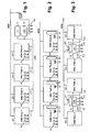
Figur 1 zeigt ein System mit vier Tieftemperatur-Luftzerlegungsanlagen (ASU Train 1
bis ASU Train 4; ASU = air separation unit). Jeder dieser vier Stränge weist eine
komplette Anlage mit Coldbox, Hauptwärmetauscher, Rektifiziersystem, Leitungen,
Maschinen und Ventilen auf. In dem Beispiel sind alle vier Tieftemperatur-Luftzerlegungsanlagen
in ihrem Inneren identisch aufgebaut. Das Rektifiziersystem
besteht vorzugsweise jeweils aus zwei Trennsäulen, einer Hochdrucksäule und einer
Niederdrucksäule, die über einen Hauptkondensator in wärmetauschender Verbindung
stehen. Jede der vier Tieftemperatur-Luftzerlegungsanlagen weist ihren eigenen
Pumpensatz P1 bis P4 auf. Jeder Pumpensatz weist in den Beispielen drei separate
Pumpen auf, die von flüssigem Sauerstoff ("Flüssigproduktstrom") aus der
Niederdrucksäule des jeweiligen Strangs gespeist werden. Jede dieser Pumpen hat
einen Nenndurchsatz, welcher der Hälfte der Nennproduktmenge an
innenverdichtetem Sauerstoff des jeweiligen Strangs entspricht. Im Normalbetrieb
laufen pro Pumpensatz P1 bis P4 jeweils zwei Pumpen; die dritte wird eingeschaltet,
wenn eine der beiden anderen ausfällt. Alternativ könnten einer, mehrere oder alle
Pumpensätze beispielsweise aus jeweils zwei Pumpen bestehen.FIG. 1 shows a system with four cryogenic air separation plants (
Der Austritt jedes Pumpensatzes ist mit dem Hauptwärmetauscher-System der jeweiligen Tieftemperatur-Luftzerlegungsanlage verbunden. Dort wird der auf hohen Druck gepumpte Sauerstoff auf die bekannte Weise entweder verdampft und angewärmt (bei unterkritischem Druck) oder angewärmt (bei überkritischem Druck) und schließlich über die Leitungen G1 bis G4 als gasförmiges Druckprodukt (GOX-gaseous oxygen) abgezogen. Als Wärmeträger-Fluid wird ein Teil der Einsatzluft, Hochdruck-Stickstoff oder ein anderes geeignetes Fluid eingesetzt.The outlet of each pump set is with the main heat exchanger system of respective cryogenic air separation plant connected. There it will be on high Pressure pumped oxygen either vaporized in the known way and heated (at subcritical pressure) or warmed (at supercritical pressure) and finally via the lines G1 to G4 as gaseous pressure product (GOX-gaseous oxygen) deducted. As a heat transfer fluid is a part of the feed air, High pressure nitrogen or another suitable fluid used.
Mindestens zeitweise wird ein Teil des flüssigen Sauerstoffs aus den Niederdrucksäulen der vier Tieftemperatur-Luftzerlegungsanlagen nicht den Pumpensätzen P1 bis P4 zugeleitet, sondern über die Leitungen L1 bis L4 als Flüssigprodukt (LOX - liquid oxygen) abgezogen. Diese Flüssigkeit wird in dem Beispiel der Figur 1 in ein als doppelter Sauerstofftank T1/T2 ausgebildetes Flüssigkeitsreservoir geleitet, das Teil eines Notversorgungssystems (backup system) ist. Das Notversorgungssystem weist außerdem einen weiteren Pumpensatz P5 und einen dampfbeheizten Wasserbadverdampfer V auf. Fällt eine oder mehrere der Tieftemperatur-Luftzerlegungsanlagen ganz oder teilweise aus, wird die fehlende GOX-Produktmenge ergänzt durch Verdampfung von flüssigem Sauerstoff in dem Notversorgungssystem.At least temporarily, a portion of the liquid oxygen from the Low-pressure columns of the four cryogenic air separation plants not the Pump sets P1 supplied to P4, but via the lines L1 to L4 as Liquid product (LOX - liquid oxygen) deducted. This liquid is in the Example of Figure 1 in a double oxygen tank T1 / T2 trained Liquid reservoir directed, part of an emergency system (backup system) is. The emergency supply system also has another pump set P5 and a steam-heated water bath evaporator V on. If one or more of the Cryogenic air separation plants wholly or partially off, is the missing GOX product quantity supplemented by evaporation of liquid oxygen in the Backup System.
In Figur 2 werden nur vier Pumpensätze benötigt an Stelle der fünf Pumpensätze von Figur 1. Dies wird dadurch erreicht, dass Innenverdichtung und Notversorgung in jeder der 4 Tieftemperatur-Luftzerlegungsanlagen integriert sind. Hier wird in jedem Strang der gesamte flüssige Sauerstoff aus der Niederdrucksäule in einen Sauerstofftank T1' bis T4' eingeleitet. Dieser ist mit dem Eintritt des jeweiligen Pumpensatzes P1' bis P4' verbunden. Der Austritt des Pumpensatzes ist einerseits mit dem Innenverdichtungs-Wärmetauscher zur Verdampfung des Drucksauerstoffs gegen das Wärmeträger-Fluid im Normalbetrieb verbunden. Andererseits ist der Austritt jedes Pumpensatzes auch mit je einem Wasserbadverdampfer V1' bis V4' verbunden, mit dessen Hilfe analog zu Figur 1 eine Notversorgung sichergestellt werden kann. Durch diese Integration des Notversorgungssystems in die einzelnen Stränge wird die Zahl der Pumpensätze von fünf auf vier reduziert und die Länge der Flüssigkeitsleitungen stark verkürzt.In Figure 2, only four pump sets are needed instead of the five pump sets of Figure 1. This is achieved by internal compaction and emergency supply in each 4 low-temperature air separation plants are integrated. Here is in every strand the entire liquid oxygen from the low-pressure column into an oxygen tank T1 ' initiated to T4 '. This is with the entry of the respective pump set P1 'to P4' connected. The outlet of the pump set is on the one hand with the inner compression heat exchanger for evaporation of the pressure oxygen against the heat transfer fluid connected in normal operation. On the other hand, the exit of each pump set is also each with a water bath evaporator V1 'connected to V4', with the aid of analogous to Figure 1 an emergency supply can be ensured. Through this integration of the Emergency supply system in the individual strands is the number of pump sets of reduced to four and greatly shortened the length of the fluid lines.
Bei dem erfindungsgemäßen Ausführungsbeispiel der Figur 3 werden demgegenüber nur zwei Pumpensätze P1" und P2" benötigt. Im Folgenden werden die beiden in der Zeichnung links angeordneten Tieftemperatur-Luftzerlegungsanlagen beschrieben, die beiden rechts dargestellten sind jedoch identisch aufgebaut. Die Bezugszeichen sind demgemäß bis auf die Indizes identisch.In the embodiment of Figure 3 according to the invention are in contrast only two pump sets P1 "and P2" needed. The following are the two in the Drawing left arranged cryogenic air separation plants described However, both shown on the right are identical. The reference numerals are accordingly identical except for the indices.
Der gesamte flüssige Sauerstoff, der in der Niederdrucksäule der ersten Tieftemperatur-Luftzerlegungsanlage (ASU Train 1) von Figur 1 gewonnen wird, strömt über eine erste Flüssigproduktleitung F1 in einen Sauerstofftank T1", der als gemeinsames Flüssigkeitsreservoir für die erste und die zweite Tieftemperatur-Luftzerlegungsanlage genutzt wird. Demgemäß wird auch der flüssige Sauerstoff aus der zweiten Tieftemperatur-Luftzerlegungsanlage über eine zweite Flüssigproduktleitung F2 in den Tank T1" eingeführt. Direkt aus diesem Tank wird nun der Pumpensatz P1" über eine oder (wie dargestellt) mehrere Flüssigleitungen LX1 beschickt, der gemäß der Erfindung gemeinsam für die erste und die zweite Tieftemperatur-Luftzerlegungsanlage genutzt wird. Im Normalbetrieb wird der Hochdrucksauerstoff, der aus dem Pumpensatz P1" austritt, jeweils zur Hälfte über die Teilstromleitungen TL1 und TL2 zu der jeweiligen Tieftemperatur-Luftzerlegungsanlage zurückgeführt um dort gegen das Wärmeträger-Fluid verdampft und/oder angewärmt zu werden. Das dabei gewonnene gasförmige Druckprodukt verlässt die Tieftemperatur-Luftzerlegungsanlagen über die Leitungen G1 beziehungsweise G2.All the liquid oxygen in the low pressure column of the first Cryogenic air separation plant (ASU Train 1) is obtained from Figure 1, flows via a first liquid product line F1 into an oxygen tank T1 ", which as common liquid reservoir for the first and the second cryogenic air separation plant is being used. Accordingly, the liquid oxygen also becomes the second cryogenic air separation plant via a second Liquid product line F2 is introduced into the tank T1 "directly from this tank will now the pump set P1 "via one or (as shown) a plurality of liquid lines LX1 loaded according to the invention together for the first and the second Cryogenic air separation plant is used. In normal operation, the High-pressure oxygen, which emerges from the pump set P1 ", in each case half over the Partial flow lines TL1 and TL2 to the respective cryogenic air separation plant returned to there evaporated against the heat transfer fluid and / or warmed to become. The thus obtained gaseous pressure product leaves the Cryogenic air separation plants via the lines G1 and G2.
Im Notbetrieb wird mindestens eine der Leitungen TL1 oder TL2 geschlossen. Die entsprechende Menge an Hochdrucksauerstoff fließt dann zu dem Wasserbadverdampfer V1" und stellt damit die Notversorgung sicher.In emergency mode, at least one of the lines TL1 or TL2 is closed. The corresponding amount of high-pressure oxygen then flows to the Water bath evaporator V1 "and thus ensures the emergency supply.
Claims (14)
dadurch gekennzeichnet, dass
characterized in that
dadurch gekennzeichnet, dass
characterized in that
Applications Claiming Priority (4)
| Application Number | Priority Date | Filing Date | Title |
|---|---|---|---|
| DE10360297 | 2003-12-20 | ||
| DE10360297 | 2003-12-20 | ||
| DE10406283 | 2004-02-09 | ||
| DE10406283 | 2004-02-09 |
Publications (1)
| Publication Number | Publication Date |
|---|---|
| EP1544559A1 true EP1544559A1 (en) | 2005-06-22 |
Family
ID=34524088
Family Applications (1)
| Application Number | Title | Priority Date | Filing Date |
|---|---|---|---|
| EP04005171A Withdrawn EP1544559A1 (en) | 2003-12-20 | 2004-03-04 | Process and device for the cryogenic separation of air |
Country Status (1)
| Country | Link |
|---|---|
| EP (1) | EP1544559A1 (en) |
Cited By (22)
| Publication number | Priority date | Publication date | Assignee | Title |
|---|---|---|---|---|
| US20100071412A1 (en) * | 2008-09-22 | 2010-03-25 | David Ross Parsnick | Method and apparatus for producing high purity oxygen |
| WO2010030427A3 (en) * | 2008-09-10 | 2010-09-16 | Praxair Technology, Inc. | Air separation refrigeration supply method |
| DE102009034979A1 (en) | 2009-04-28 | 2010-11-04 | Linde Aktiengesellschaft | Method for producing pressurized oxygen by evaporating liquid oxygen using a copper and nickel heat exchanger block |
| EP2312248A1 (en) | 2009-10-07 | 2011-04-20 | Linde Aktiengesellschaft | Method and device for obtaining pressurised oxygen and krypton/xenon |
| EP2458311A1 (en) | 2010-11-25 | 2012-05-30 | Linde Aktiengesellschaft | Method and device for creating a gaseous, pressurised product by the cryogenic decomposition of air |
| DE102010052544A1 (en) | 2010-11-25 | 2012-05-31 | Linde Ag | Process for obtaining a gaseous product by cryogenic separation of air |
| EP2520886A1 (en) | 2011-05-05 | 2012-11-07 | Linde AG | Method and device for creating gaseous oxygen pressurised product by the cryogenic decomposition of air |
| EP2568242A1 (en) | 2011-09-08 | 2013-03-13 | Linde Aktiengesellschaft | Method and device for generating of steel |
| EP2600090A1 (en) | 2011-12-01 | 2013-06-05 | Linde Aktiengesellschaft | Method and device for generating pressurised oxygen by cryogenic decomposition of air |
| DE102011121314A1 (en) | 2011-12-16 | 2013-06-20 | Linde Aktiengesellschaft | Method for producing gaseous oxygen product in main heat exchanger system in distillation column system, involves providing turbines, where one of turbines drives compressor, and other turbine drives generator |
| DE102013017590A1 (en) | 2013-10-22 | 2014-01-02 | Linde Aktiengesellschaft | Method for recovering methane-poor fluids in liquid air separation system to manufacture air product, involves vaporizing oxygen, krypton and xenon containing sump liquid in low pressure column by using multi-storey bath vaporizer |
| EP2784420A1 (en) | 2013-03-26 | 2014-10-01 | Linde Aktiengesellschaft | Method for air separation and air separation plant |
| WO2014154339A2 (en) | 2013-03-26 | 2014-10-02 | Linde Aktiengesellschaft | Method for air separation and air separation plant |
| EP2801777A1 (en) | 2013-05-08 | 2014-11-12 | Linde Aktiengesellschaft | Air separation plant with main compressor drive |
| WO2011071658A3 (en) * | 2009-12-10 | 2015-01-22 | Praxair Technology, Inc. | Oxygen production method and apparatus for enhancing the process capacity |
| EP2865978A1 (en) * | 2013-10-25 | 2015-04-29 | Linde Aktiengesellschaft | Method for low-temperature air separation and low temperature air separation plant |
| WO2014173496A3 (en) * | 2013-04-25 | 2015-08-20 | Linde Aktiengesellschaft | Method for obtaining an air product in an air separating system with temporary storage, and air separating system |
| EP2963371A1 (en) | 2014-07-05 | 2016-01-06 | Linde Aktiengesellschaft | Method and device for creating a pressurised gas product by the cryogenic decomposition of air |
| EP2963367A1 (en) | 2014-07-05 | 2016-01-06 | Linde Aktiengesellschaft | Method and device for cryogenic air separation with variable power consumption |
| EP2963369A1 (en) | 2014-07-05 | 2016-01-06 | Linde Aktiengesellschaft | Method and device for the cryogenic decomposition of air |
| EP2963370A1 (en) | 2014-07-05 | 2016-01-06 | Linde Aktiengesellschaft | Method and device for the cryogenic decomposition of air |
| WO2017127136A1 (en) | 2016-01-22 | 2017-07-27 | Praxair Technology, Inc. | Method and system for providing auxiliary refrigeration to an air separation plant |
Citations (8)
| Publication number | Priority date | Publication date | Assignee | Title |
|---|---|---|---|---|
| US5596885A (en) * | 1994-06-20 | 1997-01-28 | L'air Liquide, Societe Anonyme Pour L'etude Et L'exploitation Des Procedes Georges Claude | Process and installation for the production of gaseous oxygen under pressure |
| US5896755A (en) * | 1998-07-10 | 1999-04-27 | Praxair Technology, Inc. | Cryogenic rectification system with modular cold boxes |
| US6128921A (en) * | 1998-02-06 | 2000-10-10 | L'air Liquide | Air distillation plant comprising a plurality of cryogenic distillation units of the same type |
| EP1043558A2 (en) * | 1999-04-05 | 2000-10-11 | L'air Liquide, Societe Anonyme Pour L'etude Et L'exploitation Des Procedes Georges Claude | Integrated apparatus for generating power and/or oxygen enriched fluid, and process thereof |
| US6550234B2 (en) * | 2001-01-12 | 2003-04-22 | L'air Liquide Societe Anonyme A Directoire Et Conseil De Surveillance Pour L'etude Et L'exploitation Des Procedes Georges Claude | Integrated air-separation/energy-generation process and plant for implementing such a process |
| FR2831953A1 (en) * | 2001-11-05 | 2003-05-09 | Air Liquide | AIR DISTILLATION PROCESS WITH ARGON PRODUCTION AND CORRESPONDING AIR DISTILLATION SYSTEM |
| EP1398585A1 (en) * | 2002-09-11 | 2004-03-17 | L'air liquide, Société anonyme à Directoire et Conseil de Surveillance pour l'Etude et l'Exploitation des Procédés G. Claude | Apparatus for producing high amounts of oxygen and/or nitrogen |
| EP1435497A2 (en) * | 2002-11-01 | 2004-07-07 | L'AIR LIQUIDE, Société Anonyme à Directoire et Conseil de Surveillance pour l'Etude et l'Exploitation des | Combined air separation and natural gas liquefaction plant |
-
2004
- 2004-03-04 EP EP04005171A patent/EP1544559A1/en not_active Withdrawn
Patent Citations (8)
| Publication number | Priority date | Publication date | Assignee | Title |
|---|---|---|---|---|
| US5596885A (en) * | 1994-06-20 | 1997-01-28 | L'air Liquide, Societe Anonyme Pour L'etude Et L'exploitation Des Procedes Georges Claude | Process and installation for the production of gaseous oxygen under pressure |
| US6128921A (en) * | 1998-02-06 | 2000-10-10 | L'air Liquide | Air distillation plant comprising a plurality of cryogenic distillation units of the same type |
| US5896755A (en) * | 1998-07-10 | 1999-04-27 | Praxair Technology, Inc. | Cryogenic rectification system with modular cold boxes |
| EP1043558A2 (en) * | 1999-04-05 | 2000-10-11 | L'air Liquide, Societe Anonyme Pour L'etude Et L'exploitation Des Procedes Georges Claude | Integrated apparatus for generating power and/or oxygen enriched fluid, and process thereof |
| US6550234B2 (en) * | 2001-01-12 | 2003-04-22 | L'air Liquide Societe Anonyme A Directoire Et Conseil De Surveillance Pour L'etude Et L'exploitation Des Procedes Georges Claude | Integrated air-separation/energy-generation process and plant for implementing such a process |
| FR2831953A1 (en) * | 2001-11-05 | 2003-05-09 | Air Liquide | AIR DISTILLATION PROCESS WITH ARGON PRODUCTION AND CORRESPONDING AIR DISTILLATION SYSTEM |
| EP1398585A1 (en) * | 2002-09-11 | 2004-03-17 | L'air liquide, Société anonyme à Directoire et Conseil de Surveillance pour l'Etude et l'Exploitation des Procédés G. Claude | Apparatus for producing high amounts of oxygen and/or nitrogen |
| EP1435497A2 (en) * | 2002-11-01 | 2004-07-07 | L'AIR LIQUIDE, Société Anonyme à Directoire et Conseil de Surveillance pour l'Etude et l'Exploitation des | Combined air separation and natural gas liquefaction plant |
Non-Patent Citations (1)
| Title |
|---|
| SCHARLE W J ET AL: "OXYGEN FACILITIES FOR SYNTHETIC FUEL PROJECTS", TRANSACTIONS OF THE AMERICAN SOCIETY OF MECHANICAL ENGINEERS, SERIES B: JOURNAL OF ENGINEERING FOR INDUSTRY, ASME. NEW YORK, US, vol. 103, November 1981 (1981-11-01), pages 409 - 417, XP009026023, ISSN: 0022-0817 * |
Cited By (29)
| Publication number | Priority date | Publication date | Assignee | Title |
|---|---|---|---|---|
| WO2010030427A3 (en) * | 2008-09-10 | 2010-09-16 | Praxair Technology, Inc. | Air separation refrigeration supply method |
| US9714789B2 (en) | 2008-09-10 | 2017-07-25 | Praxair Technology, Inc. | Air separation refrigeration supply method |
| US8479535B2 (en) * | 2008-09-22 | 2013-07-09 | Praxair Technology, Inc. | Method and apparatus for producing high purity oxygen |
| US20100071412A1 (en) * | 2008-09-22 | 2010-03-25 | David Ross Parsnick | Method and apparatus for producing high purity oxygen |
| DE102009034979A1 (en) | 2009-04-28 | 2010-11-04 | Linde Aktiengesellschaft | Method for producing pressurized oxygen by evaporating liquid oxygen using a copper and nickel heat exchanger block |
| EP2312248A1 (en) | 2009-10-07 | 2011-04-20 | Linde Aktiengesellschaft | Method and device for obtaining pressurised oxygen and krypton/xenon |
| WO2011071658A3 (en) * | 2009-12-10 | 2015-01-22 | Praxair Technology, Inc. | Oxygen production method and apparatus for enhancing the process capacity |
| EP2458311A1 (en) | 2010-11-25 | 2012-05-30 | Linde Aktiengesellschaft | Method and device for creating a gaseous, pressurised product by the cryogenic decomposition of air |
| DE102010052545A1 (en) | 2010-11-25 | 2012-05-31 | Linde Aktiengesellschaft | Method and apparatus for recovering a gaseous product by cryogenic separation of air |
| DE102010052544A1 (en) | 2010-11-25 | 2012-05-31 | Linde Ag | Process for obtaining a gaseous product by cryogenic separation of air |
| EP2466236A1 (en) | 2010-11-25 | 2012-06-20 | Linde Aktiengesellschaft | Method and device for creating a gaseous, pressurised product by the cryogenic decomposition of air |
| EP2520886A1 (en) | 2011-05-05 | 2012-11-07 | Linde AG | Method and device for creating gaseous oxygen pressurised product by the cryogenic decomposition of air |
| DE102011112909A1 (en) | 2011-09-08 | 2013-03-14 | Linde Aktiengesellschaft | Process and apparatus for recovering steel |
| EP2568242A1 (en) | 2011-09-08 | 2013-03-13 | Linde Aktiengesellschaft | Method and device for generating of steel |
| EP2600090A1 (en) | 2011-12-01 | 2013-06-05 | Linde Aktiengesellschaft | Method and device for generating pressurised oxygen by cryogenic decomposition of air |
| DE102011121314A1 (en) | 2011-12-16 | 2013-06-20 | Linde Aktiengesellschaft | Method for producing gaseous oxygen product in main heat exchanger system in distillation column system, involves providing turbines, where one of turbines drives compressor, and other turbine drives generator |
| EP2784420A1 (en) | 2013-03-26 | 2014-10-01 | Linde Aktiengesellschaft | Method for air separation and air separation plant |
| WO2014154339A2 (en) | 2013-03-26 | 2014-10-02 | Linde Aktiengesellschaft | Method for air separation and air separation plant |
| US10533795B2 (en) | 2013-04-25 | 2020-01-14 | Linde Aktiengesellschaft | Method for obtaining an air product in an air separating system with temporary storage, and air separating system |
| WO2014173496A3 (en) * | 2013-04-25 | 2015-08-20 | Linde Aktiengesellschaft | Method for obtaining an air product in an air separating system with temporary storage, and air separating system |
| EP2801777A1 (en) | 2013-05-08 | 2014-11-12 | Linde Aktiengesellschaft | Air separation plant with main compressor drive |
| DE102013017590A1 (en) | 2013-10-22 | 2014-01-02 | Linde Aktiengesellschaft | Method for recovering methane-poor fluids in liquid air separation system to manufacture air product, involves vaporizing oxygen, krypton and xenon containing sump liquid in low pressure column by using multi-storey bath vaporizer |
| EP2865978A1 (en) * | 2013-10-25 | 2015-04-29 | Linde Aktiengesellschaft | Method for low-temperature air separation and low temperature air separation plant |
| EP2963367A1 (en) | 2014-07-05 | 2016-01-06 | Linde Aktiengesellschaft | Method and device for cryogenic air separation with variable power consumption |
| EP2963369A1 (en) | 2014-07-05 | 2016-01-06 | Linde Aktiengesellschaft | Method and device for the cryogenic decomposition of air |
| EP2963370A1 (en) | 2014-07-05 | 2016-01-06 | Linde Aktiengesellschaft | Method and device for the cryogenic decomposition of air |
| WO2016005031A1 (en) | 2014-07-05 | 2016-01-14 | Linde Aktiengesellschaft | Method and device for the low-temperature separation of air at variable energy consumption |
| EP2963371A1 (en) | 2014-07-05 | 2016-01-06 | Linde Aktiengesellschaft | Method and device for creating a pressurised gas product by the cryogenic decomposition of air |
| WO2017127136A1 (en) | 2016-01-22 | 2017-07-27 | Praxair Technology, Inc. | Method and system for providing auxiliary refrigeration to an air separation plant |
Similar Documents
| Publication | Publication Date | Title |
|---|---|---|
| EP1544559A1 (en) | Process and device for the cryogenic separation of air | |
| EP2235460B1 (en) | Process and device for the cryogenic separation of air | |
| EP1994344A1 (en) | Method and apparatus for fractionating air at low temperatures | |
| DE102005029274A1 (en) | Obtaining gaseous pressure product, by cryogenic separation of air implementing normal operation, emergency operation, and bypass operation | |
| EP1150082A1 (en) | Method and apparatus for heat exchange | |
| DE102010052545A1 (en) | Method and apparatus for recovering a gaseous product by cryogenic separation of air | |
| DE102010052544A1 (en) | Process for obtaining a gaseous product by cryogenic separation of air | |
| DE10013073A1 (en) | Low temperature separation of air in distillation column system uses integrated heat exchanger system for cooling e.g. air supply by indirect heat exchange during vaporization of first liquid fraction | |
| EP2236964A1 (en) | Method and device for low-temperature air separation | |
| DE10334560A1 (en) | Method for recovering krypton and xenon from air, comprises separating nitrogen and oxygen and feeding krypton- and xenon-containing fraction into enrichment column, stream of pure air being decompressed and fed into column | |
| WO2016131545A1 (en) | Method and apparatus for obtaining a compressed nitrogen product | |
| DE10228111A1 (en) | Air separation process and plant with mixing column and krypton-xenon extraction | |
| DE102010056560A1 (en) | Method for recovering compressed oxygen and compressed nitrogen by low temperature degradation of air in e.g. classical lime dual column system, for nitrogen-oxygen separation, involves driving circuit compressor by external energy | |
| DE10213212A1 (en) | Air fractionation plant in which product stream is split, carries out all compression stages in common dual flow pump | |
| DE102018000842A1 (en) | Process and apparatus for obtaining pressurized nitrogen by cryogenic separation of air | |
| EP2489968A1 (en) | Method and device for cryogenic decomposition of air | |
| EP0768503A2 (en) | Triple column air separation process | |
| WO2021104668A1 (en) | Process and plant for low-temperature fractionation of air | |
| EP3207320A1 (en) | Method and device for variably obtaining argon by means of low-temperature separation | |
| DE10209421A1 (en) | Process for recovering a compressed product comprises subjecting air to low temperature decomposition in a rectification system consisting of a high pressure column and a low pressure column | |
| DE19933558B4 (en) | Three-column process and apparatus for the cryogenic separation of air | |
| DE102007042462A1 (en) | Method and apparatus for the cryogenic separation of air | |
| DE102004016931A1 (en) | Method and apparatus for variably producing a printed product by cryogenic separation of air | |
| DE10052180A1 (en) | Three-column system for the low-temperature separation of air | |
| DE102005023434A1 (en) | Cryogenic air separation to produce oxygen and/or nitrogen comprises splitting air into several streams which are compressed, precooled and purified before being cooled and supplied to a common distillation system |
Legal Events
| Date | Code | Title | Description |
|---|---|---|---|
| PUAI | Public reference made under article 153(3) epc to a published international application that has entered the european phase |
Free format text: ORIGINAL CODE: 0009012 |
|
| AK | Designated contracting states |
Kind code of ref document: A1 Designated state(s): AT BE BG CH CY CZ DE DK EE ES FI FR GB GR HU IE IT LI LU MC NL PL PT RO SE SI SK TR |
|
| AX | Request for extension of the european patent |
Extension state: AL LT LV MK |
|
| 17P | Request for examination filed |
Effective date: 20051124 |
|
| AKX | Designation fees paid |
Designated state(s): AT BE BG CH CY CZ DE DK EE ES FI FR GB GR HU IE IT LI LU MC NL PL PT RO SE SI SK TR |
|
| 17Q | First examination report despatched |
Effective date: 20070620 |
|
| RAP1 | Party data changed (applicant data changed or rights of an application transferred) |
Owner name: LINDE AKTIENGESELLSCHAFT |
|
| RAP1 | Party data changed (applicant data changed or rights of an application transferred) |
Owner name: LINDE AG |
|
| STAA | Information on the status of an ep patent application or granted ep patent |
Free format text: STATUS: THE APPLICATION IS DEEMED TO BE WITHDRAWN |
|
| 18D | Application deemed to be withdrawn |
Effective date: 20111001 |