EP1544470B1 - Scroll compressor eccentric coupling device - Google Patents
Scroll compressor eccentric coupling device Download PDFInfo
- Publication number
- EP1544470B1 EP1544470B1 EP04077229A EP04077229A EP1544470B1 EP 1544470 B1 EP1544470 B1 EP 1544470B1 EP 04077229 A EP04077229 A EP 04077229A EP 04077229 A EP04077229 A EP 04077229A EP 1544470 B1 EP1544470 B1 EP 1544470B1
- Authority
- EP
- European Patent Office
- Prior art keywords
- crank pin
- oil
- scroll compressor
- bush
- pin hole
- Prior art date
- Legal status (The legal status is an assumption and is not a legal conclusion. Google has not performed a legal analysis and makes no representation as to the accuracy of the status listed.)
- Expired - Fee Related
Links
Images


Classifications
-
- F—MECHANICAL ENGINEERING; LIGHTING; HEATING; WEAPONS; BLASTING
- F04—POSITIVE - DISPLACEMENT MACHINES FOR LIQUIDS; PUMPS FOR LIQUIDS OR ELASTIC FLUIDS
- F04C—ROTARY-PISTON, OR OSCILLATING-PISTON, POSITIVE-DISPLACEMENT MACHINES FOR LIQUIDS; ROTARY-PISTON, OR OSCILLATING-PISTON, POSITIVE-DISPLACEMENT PUMPS
- F04C18/00—Rotary-piston pumps specially adapted for elastic fluids
- F04C18/02—Rotary-piston pumps specially adapted for elastic fluids of arcuate-engagement type, i.e. with circular translatory movement of co-operating members, each member having the same number of teeth or tooth-equivalents
-
- F—MECHANICAL ENGINEERING; LIGHTING; HEATING; WEAPONS; BLASTING
- F04—POSITIVE - DISPLACEMENT MACHINES FOR LIQUIDS; PUMPS FOR LIQUIDS OR ELASTIC FLUIDS
- F04C—ROTARY-PISTON, OR OSCILLATING-PISTON, POSITIVE-DISPLACEMENT MACHINES FOR LIQUIDS; ROTARY-PISTON, OR OSCILLATING-PISTON, POSITIVE-DISPLACEMENT PUMPS
- F04C29/00—Component parts, details or accessories of pumps or pumping installations, not provided for in groups F04C18/00 - F04C28/00
- F04C29/0042—Driving elements, brakes, couplings, transmissions specially adapted for pumps
- F04C29/005—Means for transmitting movement from the prime mover to driven parts of the pump, e.g. clutches, couplings, transmissions
- F04C29/0057—Means for transmitting movement from the prime mover to driven parts of the pump, e.g. clutches, couplings, transmissions for eccentric movement
-
- F—MECHANICAL ENGINEERING; LIGHTING; HEATING; WEAPONS; BLASTING
- F04—POSITIVE - DISPLACEMENT MACHINES FOR LIQUIDS; PUMPS FOR LIQUIDS OR ELASTIC FLUIDS
- F04C—ROTARY-PISTON, OR OSCILLATING-PISTON, POSITIVE-DISPLACEMENT MACHINES FOR LIQUIDS; ROTARY-PISTON, OR OSCILLATING-PISTON, POSITIVE-DISPLACEMENT PUMPS
- F04C18/00—Rotary-piston pumps specially adapted for elastic fluids
- F04C18/02—Rotary-piston pumps specially adapted for elastic fluids of arcuate-engagement type, i.e. with circular translatory movement of co-operating members, each member having the same number of teeth or tooth-equivalents
- F04C18/0207—Rotary-piston pumps specially adapted for elastic fluids of arcuate-engagement type, i.e. with circular translatory movement of co-operating members, each member having the same number of teeth or tooth-equivalents both members having co-operating elements in spiral form
- F04C18/0215—Rotary-piston pumps specially adapted for elastic fluids of arcuate-engagement type, i.e. with circular translatory movement of co-operating members, each member having the same number of teeth or tooth-equivalents both members having co-operating elements in spiral form where only one member is moving
-
- F—MECHANICAL ENGINEERING; LIGHTING; HEATING; WEAPONS; BLASTING
- F04—POSITIVE - DISPLACEMENT MACHINES FOR LIQUIDS; PUMPS FOR LIQUIDS OR ELASTIC FLUIDS
- F04C—ROTARY-PISTON, OR OSCILLATING-PISTON, POSITIVE-DISPLACEMENT MACHINES FOR LIQUIDS; ROTARY-PISTON, OR OSCILLATING-PISTON, POSITIVE-DISPLACEMENT PUMPS
- F04C29/00—Component parts, details or accessories of pumps or pumping installations, not provided for in groups F04C18/00 - F04C28/00
- F04C29/02—Lubrication; Lubricant separation
- F04C29/023—Lubricant distribution through a hollow driving shaft
Definitions
- the present invention relates to a slide bush of a scroll compressor, and more particularly to an eccentric coupling device in a radial compliance scroll compressor as disclosed e.g. in US 6 053 754 and US 6 361 296 which is capable of sufficiently supplying oil, fed through an oil passage of a crankshaft, between a slide bush and a bearing to lubricate frictional surfaces thereof.
- a scroll compressor includes upper and lower scrolls respectively provided with involute-shaped wraps engaged with each other.
- One of the scrolls performs an orbiting motion with respect to the other scroll to reduce the volume of spaces defined between the scrolls, thereby compressing gas confined in the spaces.
- a radial compliance scroll compressor As such a conventional compressor, a radial compliance scroll compressor is known.
- an orbiting scroll thereof In such a radial compliance scroll compressor, an orbiting scroll thereof is backwardly moved when liquid refrigerant, oil or foreign matter is introduced into compression chambers defined between the orbiting scroll and the other scroll, that is, a fixed scroll, thereby abnormally increasing the gas pressure in the compression chambers.
- the backward movement of the orbiting scroll it is possible to prevent the wraps of the scrolls from being damaged due to the abnormally increased gas pressure.
- FIG. 1 is a sectional view illustrating the entire configuration of a conventional radial compliance scroll compressor.
- the conventional radial compliance scroll compressor includes a shell 1, and main and sub frames 2 and 3 respectively arranged in the shell 1 at upper and lower portions of the shell 1.
- a stator 4 which has a hollow structure, is interposed between the main and sub frames 2 and 3 within the shell 1.
- a rotor 5 is arranged inside the stator 4 such that it rotates when current flows through the stator 4.
- a vertical crankshaft 6 extends axially through a central portion of the rotor 5 while being fixed to the rotor 5 so that it is rotated along with the rotor 5.
- the crankshaft 6 has upper and lower ends protruded beyond the rotor 5, and rotatably fitted in the main and sub frames 2 and 3, respectively.
- the crankshaft 6 is rotatably supported by the main and sub frames 2 and 3.
- An orbiting scroll 7 is mounted to an upper surface of the main frame 2 in the shell 1.
- the orbiting scroll 7 is coupled, at a lower portion thereof, with the upper end of the crankshaft 6, which is protruded through the main frame 2, so that it performs an orbiting motion in accordance with rotation of the crankshaft 6.
- the orbiting scroll 7 is provided, at an upper portion thereof, with an orbiting wrap 7a having an involute shape.
- the orbiting wrap 7a extends upwardly from an upper surface of the orbiting scroll 7.
- a fixed scroll 8 is arranged on the orbiting scroll 7 in the shell 1 while being fixed to the shell 1.
- the fixed scroll 8 is provided, at a lower portion thereof, with a fixed wrap 8a adapted to be engaged with the orbiting wrap 7a of the orbiting scroll 7 such that compression chambers 22 are defined between the wraps 7a and 8a.
- the orbiting scroll 7 is eccentrically coupled to the crankshaft 6.
- the crankshaft 6 is provided with a crank pin 10 upwardly protruded from the upper end of the crankshaft 6 at a position radially spaced apart from the center of the upper end of the crankshaft 6 by a certain distance.
- the orbiting scroll 7 is provided, at the lower portion thereof, with a boss 7b centrally protruded from a lower surface of the orbiting scroll 7.
- a bearing 11 is forcibly fitted in the boss 7b.
- a slide bush 12 is slidably fitted around the crank pin 10.
- an Oldham ring 9 is arranged between the main frame 2 and the orbiting scroll 7.
- An oil passage 6a extends vertically throughout the crankshaft 6.
- Upper and lower balance weight members are provided at upper and lower surfaces of the rotor 5, respectively, in order to prevent a rotation unbalance of the crankshaft 6 caused by the crank pin 10.
- reference numerals 15 and 16 designate suction and discharge pipes, respectively
- reference numerals 17 and 18 designate a discharge port and a discharge chamber, respectively
- reference numeral 19 designates a check valve
- reference numeral 20 designates oil
- reference numeral 21 designates an oil propeller.
- the rotor 5 When current flows through the stator 4, the rotor 5 is rotated inside the stator 4, thereby causing the crankshaft 6 to rotate.
- the orbiting scroll 7 coupled to the crank pin 10 of the crankshaft 6 performs an orbiting motion with an orbiting radius defined between the center of the crankshaft 6 and the center of the orbiting scroll 7.
- the compression chambers 22, which are defined between the orbiting wrap 7a and the fixed wrap 8a, are gradually reduced in volume, so that gaseous refrigerant sucked into each compression chamber 22 via the suction pipe 15 is compressed to high pressure.
- the compressed high-pressure gaseous refrigerant is subsequently discharged into the discharge chamber 18 via the discharge port 17.
- the compressed high-pressure gaseous refrigerant is then outwardly discharged from the discharge chamber 18 via the discharge pipe 16.
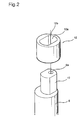
- FIG. 2 is an exploded perspective view illustrating the structure of the conventional slide bush.
- the slide bush 12 is fitted in the boss 7b of the orbiting scroll 7.
- the slide bush 12 is provided with a crank pin hole 12a so that it is fitted around the crank pin 10.
- the slide bush 12 is radially shifted in a backward direction when an abnormal compression operation is carried out to cause an abnormal increase in the gas pressure of the compression chambers, thereby causing the orbiting scroll 7 to be radially shifted in the backward direction such that the orbiting wrap 7a is moved away from the fixed wrap 8a.
- An oil supply groove 12b is provided at an outer peripheral portion of the slide bush 12 at one side of the slide bush 12. The oil supply groove 12b may be formed by cutting out a desired peripheral portion of the slide bush 12.
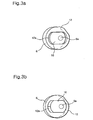
- FIGS. 3a to 3c illustrate a radial backward movement of the conventional slide bush.
- FIG. 3a is a cross-sectional view illustrating a state of the slide bush in a normal operation of the scroll compressor.
- FIG. 3b is a cross-sectional view illustrating a backwardly moved state of the slide bush caused by an abnormal operation of the scroll compressor.
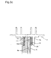
- FIG. 3c is a sectional view illustrating supply of oil in the normal operation of the scroll compressor.
- the crank pin 10 performs an orbiting motion along with the slide bush 12 in accordance with rotation of the crankshaft 6.
- the slide bush 12 is radially shifted in a backward direction along the crank pin hole 12a with respect to the crank pin 10 in response to the increased gas pressure.
- oil 20 is supplied to the eccentric coupling device via the oil passage 6a formed through the crankshaft 6 during the normal operation of the scroll compressor.
- the oil 20 supplied to the eccentric coupling device is discharged from an upper end of the crank pin 10, so that it lubricates the bearing 11 and slide bush 12 fitted in the boss 7b of the orbiting scroll 7 while being in frictional contact with each other, thereby reducing friction generated between the bearing 11 and the slide bush 12.
- the oil 20 also serves to cool the stator 4 and rotor 5.
- crank pin hole 12a is enlarged at one side of the slide bush 12, as shown in FIG. 3b. That is, the crank pin hole 12a has an enlarged gap at one side of the slide bush 12.
- the oil discharged from the upper end of the crank pin 10 via the oil passage 6a of the crankshaft 6 is mainly discharged through the enlarged gap of the crank pin hole 12a without being sufficiently supplied between the bearing 11 and the slide bush 12, that is, frictional surfaces thereof.
- the orbiting scroll cannot perform a smooth orbiting motion, thereby causing a degradation in the compression efficiency of the scroll compressor.
- the present invention has been made in view of the above mentioned problems, and an object of the invention is to provide an eccentric coupling device in a radial compliance scroll compressor which is capable of sufficiently supplying oil, fed through an oil passage of a crankshaft, between a bush and a bearing to lubricate frictional surfaces thereof.
- Another object of the invention is to provide an eccentric coupling device in a radial compliance scroll compressor which is capable of sufficiently supplying oil, fed through an oil passage of a crankshaft, between a bush and a bearing to lubricate frictional surfaces thereof, by use of a cover member, while preventing the cover member from being separated due to a tilting phenomenon caused by an abnormal increase in the gas pressure of compression chambers defined in the scroll compressor.
- Another object of the invention is to provide an eccentric coupling device in a radial compliance scroll compressor which is capable of allowing convenient and simple manufacture of a bush thereof.
- the present invention provides a radial compliance scroll compressor comprising: a bush rotatably fitted in an inner surface of a boss of an orbiting scroll, and provided with a crank pin hole extending vertically throughout the bush; a crank pin eccentrically arranged at an upper end of a crankshaft adapted to orbit the orbiting scroll, and fitted in the crank pin hole while allowing a movement of the bush in the crank pin hole, the crank pin having an oil passage communicating with an oil passage formed through the crankshaft; and a cover member fitted in an upper end portion of the crank pin hole, and adapted to guide oil fed through the oil passage of the crank pin such that the oil is supplied between an outer peripheral surface of the bush and an inner peripheral surface of the boss.
- the crank pin is fitted in the crank pin hole such that an upper end thereof is arranged at a level lower than an upper end of the bush.
- the cover member may comprise a body plate tightly fitted in the crank pin hole over the crank pin, and an oil hole formed through the body plate at a position corresponding to the oil passage of the crank pin.
- the cover member may comprise a body plate tightly fitted in the crank pin hole over the crank pin, and an oil hole formed through the body plate at a position corresponding to the oil passage of the crank pin.
- the body plate may have a thickness equal to a height from an upper end of the crank pin to an upper end of the bush so that the body plate is in close surface contact with the upper end of the crank pin at a lower surface thereof.
- the oil hole may have a diameter larger than a diameter of the oil passage of the crank pin. Accordingly, oil emerging from the oil passage can rapidly pass through the oil hole, so that it can be rapidly supplied onto the upper surface of the body plate without a reduction in the flow rate thereof caused by the oil hole.
- the present invention provides a radial compliance scroll compressor comprising: a bush rotatably fitted in an inner surface of a boss of an orbiting scroll, and provided with a crank pin hole extending vertically throughout the bush; a crank pin eccentrically arranged at an upper end of a crankshaft adapted to orbit the orbiting scroll, and fitted in the crank pin hole while allowing a radial movement of the bush in the crank pin hole, the crank pin having an oil passage communicating with an oil passage formed through the crankshaft; a cover member fitted in an upper end portion of the crank pin hole, and adapted to guide oil fed through the oil passage of the crank pin such that the oil is supplied between an outer peripheral surface of the bush and an inner peripheral surface of the boss; and a separation preventing member provided at an upper end of the crank pin hole, and adapted to prevent the cover member from being separated from the crank pin hole.
- the crank pin is fitted in the crank pin hole such that an upper end thereof is arranged at a level lower than an upper end of the bush.
- the separation preventing member may comprise a separation preventing jaw radially inwardly protruded from the upper end of the crank pin hole, and adapted to be in contact with the upper surface of the cover member.
- the present invention provides a radial compliance scroll compressor comprising: a bush rotatably fitted in an inner surface of a boss of an orbiting scroll, and provided with a crank pin hole extending vertically throughout the bush; a crank pin eccentrically arranged at an upper end of a crankshaft adapted to orbit the orbiting scroll, and fitted in the crank pin hole while allowing a radial movement of the bush in the crank pin hole, the crank pin having an oil passage communicating with an oil passage formed through the crankshaft; and a cover member provided at an upper end of the bush while being integral with the bush, and adapted to close an upper end of the crank pin hole, the cover member having an oil hole formed through the cover member at a position corresponding to the oil passage of the crank pin.
- the crank pin is fitted in the crank pin hole such that an upper end thereof is arranged at a level lower than an upper end of the bush.
- the cover member has a thickness equal to a height from an upper end of the crank pin to an upper end of the bush so that the cover member is in close surface contact with the upper end of the crank pin at a lower surface thereof.
- FIG. 4 is an exploded perspective view illustrating an eccentric coupling device according to an embodiment of the present invention.
- the eccentric coupling device may be applied to the radial compliance scroll compressor shown in FIG. 1.
- the eccentric coupling device will be described in conjunction with the case in which it is applied to the radial compliance scroll compressor shown in FIG. 1.
- elements respectively corresponding to those in FIGS. 1 and 2 will be designated by the same reference numerals.
- the eccentric coupling device includes a slide bush 12 fitted in a bearing 11 (FIG. 6) fixedly fitted in a boss 7b of an orbiting scroll 7.
- the slide bush 12 is provided with a crank pin hole 12a.
- the eccentric coupling device also includes a crank pin 10 fitted in the crank pin hole 12a of the slide bush 12 such that it allows a radial movement of the slide bush 12 along the crank pin hole 12a.
- the crank pin 10 is provided with an oil passage 6a.
- the eccentric coupling device further includes a cover member 120 fitted in the crank pin hole 12a of the slide bush 12 at an upper end portion of the crank pin hole 12a, and adapted to guide oil, fed through the oil passage 6a, to be supplied between the bearing 11 and the slide bush 12.
- the crank pin 10 has a length shorter than that of the slide bush 12 such that an upper end thereof is arranged at a level lower than an upper end of the slide bush 12 under the condition in which the slide bush 12 is fitted around the crank pin 10. With this structure, a space for receiving the cover member 120 is provided at the upper end portion of the crank pin hole 12a.
- crank pin 10 is provided at an upper end of the crankshaft 6 such that it is eccentrically arranged with respect to the crankshaft 6.
- the oil passage 6a is connected to an oil passage extending throughout the crankshaft 6.
- the oil passage of the crankshaft 6 is also denoted by the reference numeral "6a".
- the cover member 120 includes a body plate 122 tightly fitted in the crank pin hole 12a over the crank pin 10, and an oil hole 124 formed through the body plate 122 at a position corresponding to the oil passage 6a.
- the body plate 122 serves to guide oil, fed through the oil passage 6a, to an upper surface thereof through the oil hole 124, while cutting off discharge of the oil through a gap defined between the crank pin 10 and the crank pin hole 12a.
- the oil discharged onto the upper surface of the body plate 122 can smoothly flow along an outer peripheral surface of the slide bush 12, so that it can lubricate the frictional surfaces of the bearing 11 and slide bush 12.
- the body plate 122 has a thickness equal to a height from the upper end of the crank pin 10 to the upper end of the slide bush 12.
- the body plate 122 is in close surface contact with the upper end of the crank pin 10 at a lower surface thereof. In accordance with the close surface contact of the body plate 122 with the crank pin 10, it is possible to cut off discharge of oil through the gap defined between the crank pin 10 and the crank pin hole 12a. Accordingly, it is possible to sufficiently supply oil onto the upper surface of the body plate 122.
- the oil hole 124 has a diameter larger than that of the oil passage 6a so that oil emerging from the oil passage 6a rapidly passes through the oil hole 124. Accordingly, the oil can be rapidly supplied onto the upper surface of the body plate 122 without a reduction in the flow rate thereof caused by the oil hole 124.
- FIG. 5 is a sectional view illustrating an assembled state of the eccentric coupling device shown in FIG. 4.
- the body plate 122 of the cover member 120 is tightly fitted in the crank pin hole 12a of the slide bush 12 such that the oil hole 124 is aligned with the oil passage 6a of the crank pin 10.
- the upper surface of the body plate 122 is flush with the upper end of the slide bush 12.
- the lower surface of the body plate 122 is in close contact with the upper end of the crank pin 10.
- the diameter of the oil hole 124 is larger than the diameter of the oil passage 6a.
- the oil passage 6a extends through the crankshaft 6 and crank pin 10, and communicates with the oil hole 124.
- oil fed through the oil passage 6a is discharged from the oil hole 124 onto the upper surface of the body plate 122, so that it flows horizontally along the upper surface of the body plate 122, and then flows downwardly along the outer peripheral surface of the slide bush 12.
- FIG. 6 is a sectional view illustrating a flow of oil along the slide bush in the eccentric coupling device shown in FIG. 4.
- the bearing 11 is tightly fitted in the boss 7b provided at the lower surface of the orbiting scroll 7.
- the slide bush 12 is rotatably fitted in the bearing 11.
- crank pin 10 of the crankshaft 6 is fitted in the crank pin hole 12a of the slide bush 12 such that the slide bush 12 is radially slidable therealong.
- the body plate 122 of the cover member 120 is tightly fitted in the crank pin hole 12a over the crank pin 10 such that it is in close contact with the upper end of the crank pin 10.
- Oil is upwardly fed through the oil passage 6a during rotation of the crankshaft 6.
- the oil continuously passes through the oil hole 124 without being discharged through the gap defined between the crank pin 10 and the crank pin hole 12a in accordance with the function of the body plate 122.
- the oil is then discharged onto the upper surface of the body plate 122. Subsequently, the discharged oil flows horizontally along the upper surface of the body plate 122, and then flows downwardly between the inner peripheral surface of the bearing 11 and the outer peripheral surface of the slide bush 12, so that it is supplied between the bearing 11 and the slide bush 12.
- the oil supplied between the bearing 11 and the slide bush 12 lubricates the frictional surfaces of the bearing 11 and slide bush 12, thereby reducing friction generated between the bearing 11 and the slide bush 12. Thus, damage to the bearing 11 and slide bush 12 caused by the friction is prevented.
- FIG. 7 is a sectional view illustrating an eccentric coupling device according to another embodiment of the present invention.
- the eccentric coupling device may be applied to the radial compliance scroll compressor shown in FIG. 1.
- the eccentric coupling device will be described in conjunction with the case in which it is applied to the radial compliance scroll compressor shown in FIG. 1.
- elements respectively corresponding to those in FIGS. 1 and 2, and FIGS. 4 to 6 will be designated by the same reference numerals.
- the eccentric coupling device includes a slide bush 12 fitted in a bearing 11 (FIG. 6) fixedly fitted in a boss 7b of an orbiting scroll 7.
- the slide bush 12 is provided with a crank pin hole 12a.
- the eccentric coupling device also includes a crank pin 10 fitted in the crank pin hole 12a of the slide bush 12 such that it allows a radial movement of the slide bush 12 along the crank pin hole 12a.
- the crank pin 10 is provided with an oil passage 6a.
- the eccentric coupling device further includes a cover member 120 fitted in the crank pin hole 12a of the slide bush 12 at an upper end portion of the crank pin hole 12a, and adapted to guide oil, fed through the oil passage 6a, to be supplied between the bearing 11 and the slide bush 12.
- this eccentric coupling device further includes a separation preventing means 130 provided at an upper end of the crank pin hole 12a, and adapted to prevent the cover member 120 from being separated from the crank pin hole 12a through the upper end of the crank pin hole 12a, in accordance with this embodiment of the present invention.
- the crank pin 10 has a length shorter than that of the slide bush 12 such that an upper end thereof is arranged at a level lower than an upper end of the slide bush 12 under the condition in which the slide bush 12 is fitted around the crank pin 10. With this structure, a space for receiving the cover member 120 is provided at the upper end portion of the crank pin hole 12a.
- the crank pin 10 is provided at an upper end of the crankshaft 6 such that it is eccentrically arranged with respect to the crankshaft 6.
- the oil passage 6a is connected to an oil passage extending throughout the crankshaft 6.
- the oil passage of the crankshaft 6 is also denoted by the reference numeral "6a".
- the cover member 120 includes a body plate 122 tightly fitted in the crank pin hole 12a over the crank pin 10, and an oil hole 124 formed through the body plate 122 at a position corresponding to the oil passage 6a.
- the body plate 122 serves to guide oil, fed through the oil passage 6a, to an upper surface thereof through the oil hole 124, while cutting off discharge of the oil through a gap defined between the crank pin 10 and the crank pin hole 12a.
- the body plate 122 has a thickness equal to a height from the upper end of the crank pin 10 to the upper end of the slide bush 12.
- the oil hole 124 has a diameter larger than that of the oil passage 6a.
- the separation preventing means 130 comprises a separation preventing jaw 132 radially inwardly protruded from the upper end of the crank pin hole 12a, and adapted to be in contact with the upper surface of the cover member 120.
- the separation preventing jaw 132 serves to prevent the cover member 120 from rising upwardly, thereby preventing the cover member 120 from being separated from the crank pin hole 12a.
- the body plate 122 of the cover member 120 is upwardly inserted into the crank pin hole 12a until the upper end thereof comes into contact with a lower surface of the separation preventing jaw 132. Thus, the body plate 122 is firmly held in the slide bush 12.
- FIG. 8 is a sectional view illustrating an eccentric coupling device according to another embodiment of the present invention.
- the eccentric coupling device may be applied to the radial compliance scroll compressor shown in FIG. 1.
- the eccentric coupling device will be described in conjunction with the case in which it is applied to the radial compliance scroll compressor shown in FIG. 1.
- elements respectively corresponding to those in FIGS. 1 and 2, and FIGS. 4 to 6 will be designated by the same reference numerals.
- the eccentric coupling device includes a slide bush 12 fitted in a bearing 11 (FIG. 6) fixedly fitted in a boss 7b of an orbiting scroll 7.
- the slide bush 12 is provided with a crank pin hole 12a.
- the eccentric coupling device also includes a crank pin 10 fitted in the crank pin hole 12a of the slide bush 12 such that it allows a radial movement of the slide bush 12 along the crank pin hole 12a.
- the crank pin 10 is provided with an oil passage 6a.
- the eccentric coupling device further includes a cover member 120 provided at an upper end of the slide bush 12 while being integral with the slide bush 12, and adapted to close an upper end of the crank pin hole 12a.
- the cover member 120 is provided with an oil hole 124 at a position corresponding to the oil passage 6a.
- the crank pin 10 has a length shorter than that of the slide bush 12 such that an upper end thereof is arranged at a level lower than an upper end of the slide bush 12 under the condition in which the slide bush 12 is fitted around the crank pin 10.
- the crank pin 10 is provided at an upper end of the crankshaft 6 such that it is eccentrically arranged with respect to the crankshaft 6.
- the oil passage 6a is connected to an oil passage extending throughout the crankshaft 6.
- the oil passage of the crankshaft 6 is also denoted by the reference numeral "6a".
- the cover member 120 has a thickness equal to a height from the upper end of the crank pin 10 to the upper end of the slide bush 12.
- the oil hole 124 has a diameter larger than that of the oil passage 6a.
- the cover member 120 is formed to be integral with the slide bush 12, and provided with the oil hole 124. In accordance with this embodiment of the present invention, it is possible to sufficiently supply oil between the frictional surfaces of the bearing 11 and slide bush 12. It is also possible to simply manufacture the cover member 120. That is, since the cover member 120 is integral with the slide bush 12, the manufacture thereof can be achieved simultaneously with the manufacture of the slide bush 12. Also, a separate assembly of the cover member 120 is unnecessary.
- oil fed through the oil passage of the crankshaft can be sufficiently supplied between the slide bush and the bearing, that is, the frictional surfaces thereof, without being discharged through the gap defined between the crank pin and the crank pin hole. Accordingly, it is possible to minimize friction generated between the frictional surfaces, thereby achieving a smooth orbiting motion of the orbiting scroll without generation of frictional heat. Thus, an improvement in compression efficiency is achieved.
- the separation preventing jaw is provided at the upper end of the crank pin hole formed through the slide bush, the cover member fitted in the slide bush is not separated from the slide bush even when it receives a pressure generated due to a tilting phenomenon caused by an abnormal increase in the gas pressure of the compression chambers.
- cover member is integral with the slide bush, it is unnecessary to perform a troublesome process of assembling the cover member to the slide bush. Thus, the assembly of the slide bush can be conveniently and simply achieved.
Landscapes
- Engineering & Computer Science (AREA)
- Mechanical Engineering (AREA)
- General Engineering & Computer Science (AREA)
- Rotary Pumps (AREA)
Applications Claiming Priority (2)
| Application Number | Priority Date | Filing Date | Title |
|---|---|---|---|
| KR2003091942 | 2003-12-16 | ||
| KR10-2003-0091942A KR100534571B1 (ko) | 2003-12-16 | 2003-12-16 | 스크롤 압축기의 슬라이드 부시 |
Publications (3)
| Publication Number | Publication Date |
|---|---|
| EP1544470A2 EP1544470A2 (en) | 2005-06-22 |
| EP1544470A3 EP1544470A3 (en) | 2005-11-02 |
| EP1544470B1 true EP1544470B1 (en) | 2007-03-07 |
Family
ID=34511233
Family Applications (1)
| Application Number | Title | Priority Date | Filing Date |
|---|---|---|---|
| EP04077229A Expired - Fee Related EP1544470B1 (en) | 2003-12-16 | 2004-08-04 | Scroll compressor eccentric coupling device |
Country Status (5)
| Country | Link |
|---|---|
| US (1) | US7160089B2 (ko) |
| EP (1) | EP1544470B1 (ko) |
| KR (1) | KR100534571B1 (ko) |
| CN (1) | CN100371605C (ko) |
| DE (1) | DE602004005140T2 (ko) |
Families Citing this family (12)
| Publication number | Priority date | Publication date | Assignee | Title |
|---|---|---|---|---|
| KR100624373B1 (ko) * | 2004-10-06 | 2006-09-18 | 엘지전자 주식회사 | 선회베인 압축기의 선회 반경 가변 장치 |
| JP4367941B2 (ja) * | 2005-01-25 | 2009-11-18 | キヤノン株式会社 | 中継装置、画像供給装置及び印刷システムとその制御方法 |
| US20060233654A1 (en) * | 2005-04-11 | 2006-10-19 | Tecumseh Products Company | Compressor with radial compliance mechanism |
| KR100759137B1 (ko) * | 2005-12-23 | 2007-09-14 | 엘지전자 주식회사 | 스크롤 압축기의 베이퍼 락 방지 구조 |
| CN101684811A (zh) * | 2008-09-28 | 2010-03-31 | 乐金电子(天津)电器有限公司 | 涡旋式压缩机 |
| CN102678563B (zh) * | 2011-03-08 | 2016-01-27 | 上海日立电器有限公司 | 一种涡旋压缩机的径向柔性结构 |
| JP5540192B2 (ja) * | 2012-12-03 | 2014-07-02 | 株式会社リッチストーン | スクロール液ポンプ |
| JP6328330B2 (ja) * | 2015-04-22 | 2018-05-23 | 三菱電機株式会社 | スクロール圧縮機 |
| CN105952644B (zh) * | 2016-07-07 | 2018-12-07 | 珠海格力节能环保制冷技术研究中心有限公司 | 一种旋叶式压缩机 |
| CN107598531B (zh) * | 2017-09-18 | 2024-03-26 | 广东富华重工制造有限公司 | 用于将衬套装入转向节销孔的装置 |
| CN111089055A (zh) * | 2018-10-23 | 2020-05-01 | 艾默生环境优化技术(苏州)有限公司 | 涡旋压缩机 |
| EP4242460A4 (en) * | 2020-11-09 | 2024-01-10 | Mitsubishi Electric Corp | SPIRAL COMPRESSOR |
Family Cites Families (14)
| Publication number | Priority date | Publication date | Assignee | Title |
|---|---|---|---|---|
| TW316941B (ko) * | 1994-03-15 | 1997-10-01 | Nippon Denso Co | |
| US5609478A (en) * | 1995-11-06 | 1997-03-11 | Alliance Compressors | Radial compliance mechanism for corotating scroll apparatus |
| JPH09151866A (ja) * | 1995-11-30 | 1997-06-10 | Sanyo Electric Co Ltd | スクロール圧縮機 |
| JP2915852B2 (ja) * | 1996-09-06 | 1999-07-05 | 三菱重工業株式会社 | スクロール型圧縮機 |
| US6074186A (en) * | 1997-10-27 | 2000-06-13 | Carrier Corporation | Lubrication systems for scroll compressors |
| JP3279236B2 (ja) | 1997-11-26 | 2002-04-30 | ダイキン工業株式会社 | スクロール型流体機械 |
| US6053714A (en) * | 1997-12-12 | 2000-04-25 | Scroll Technologies, Inc. | Scroll compressor with slider block |
| KR100308292B1 (ko) * | 1998-12-31 | 2002-01-17 | 구자홍 | 스크롤압축기의슬라이더부시가변반경구조 |
| JP2001012370A (ja) * | 1999-06-24 | 2001-01-16 | Mitsubishi Heavy Ind Ltd | スクロール型圧縮機 |
| KR20010076883A (ko) * | 2000-01-28 | 2001-08-17 | 구자홍 | 스크롤 압축기의 축방향 누설 저감장치 |
| JP2001342977A (ja) * | 2000-06-01 | 2001-12-14 | Keihin Corp | スクロール型圧縮機 |
| KR100371171B1 (ko) * | 2000-06-30 | 2003-02-05 | 엘지전자 주식회사 | 스크롤 압축기의 반경방향 순응구조 |
| KR100425740B1 (ko) * | 2002-02-09 | 2004-04-01 | 엘지전자 주식회사 | 스크롤 압축기의 마찰손실 저감장치 |
| JP2003286975A (ja) * | 2002-03-27 | 2003-10-10 | Mitsubishi Electric Corp | スクロール圧縮機 |
-
2003
- 2003-12-16 KR KR10-2003-0091942A patent/KR100534571B1/ko not_active IP Right Cessation
-
2004
- 2004-07-14 CN CNB2004100638771A patent/CN100371605C/zh not_active Expired - Fee Related
- 2004-07-20 US US10/893,941 patent/US7160089B2/en active Active
- 2004-08-04 EP EP04077229A patent/EP1544470B1/en not_active Expired - Fee Related
- 2004-08-04 DE DE602004005140T patent/DE602004005140T2/de active Active
Also Published As
| Publication number | Publication date |
|---|---|
| KR20050060341A (ko) | 2005-06-22 |
| EP1544470A2 (en) | 2005-06-22 |
| EP1544470A3 (en) | 2005-11-02 |
| CN100371605C (zh) | 2008-02-27 |
| DE602004005140T2 (de) | 2007-11-15 |
| KR100534571B1 (ko) | 2005-12-08 |
| US7160089B2 (en) | 2007-01-09 |
| CN1629489A (zh) | 2005-06-22 |
| US20050129555A1 (en) | 2005-06-16 |
| DE602004005140D1 (de) | 2007-04-19 |
Similar Documents
| Publication | Publication Date | Title |
|---|---|---|
| US7150609B2 (en) | Eccentric coupling device in radial compliance scroll compressor | |
| US5342183A (en) | Scroll compressor with discharge diffuser | |
| KR100538063B1 (ko) | 압축기 | |
| US6071100A (en) | Scroll compressor having lubrication of the rotation preventing member | |
| US5931650A (en) | Hermetic electric scroll compressor having a lubricating passage in the orbiting scroll | |
| EP1544470B1 (en) | Scroll compressor eccentric coupling device | |
| EP1508699A1 (en) | Scroll-type compressor | |
| US20080304994A1 (en) | Scroll Fluid Machine | |
| US20120148434A1 (en) | Scroll Fluid Machine | |
| JP4519489B2 (ja) | スクロール圧縮機 | |
| US4997349A (en) | Lubrication system for the crank mechanism of a scroll compressor | |
| US20090317276A1 (en) | Scroll compressor having rotation prevention mechanism | |
| US7175402B2 (en) | Eccentric coupling device in radial compliance scroll compressor | |
| EP1544468A2 (en) | Scroll compressor eccentric bush structure | |
| US11053941B2 (en) | Motor-operated compressor | |
| JP4512479B2 (ja) | スクロール圧縮機 | |
| US20200080557A1 (en) | Motor-operated compressor | |
| EP3567212A1 (en) | Compressor having oldham's ring | |
| JP2003301784A (ja) | スクロール流体機械の自転防止機構 | |
| US8939741B2 (en) | Scroll compressor | |
| US11927186B2 (en) | Scroll compressor | |
| KR100308284B1 (ko) | 스크롤압축기의역회전방지장치 | |
| JP2000097171A (ja) | スクロール圧縮機およびそれを使用した冷凍システム | |
| JP2548517B2 (ja) | 密閉形スクロール流体装置 | |
| KR20240014320A (ko) | 스크롤 압축기 |
Legal Events
| Date | Code | Title | Description |
|---|---|---|---|
| PUAI | Public reference made under article 153(3) epc to a published international application that has entered the european phase |
Free format text: ORIGINAL CODE: 0009012 |
|
| AK | Designated contracting states |
Kind code of ref document: A2 Designated state(s): AT BE BG CH CY CZ DE DK EE ES FI FR GB GR HU IE IT LI LU MC NL PL PT RO SE SI SK TR |
|
| AX | Request for extension of the european patent |
Extension state: AL HR LT LV MK |
|
| PUAL | Search report despatched |
Free format text: ORIGINAL CODE: 0009013 |
|
| AK | Designated contracting states |
Kind code of ref document: A3 Designated state(s): AT BE BG CH CY CZ DE DK EE ES FI FR GB GR HU IE IT LI LU MC NL PL PT RO SE SI SK TR |
|
| AX | Request for extension of the european patent |
Extension state: AL HR LT LV MK |
|
| RIN1 | Information on inventor provided before grant (corrected) |
Inventor name: HONG, SOG-KIE Inventor name: CHOI, SONG Inventor name: PARK, HONG HEE Inventor name: CHO, NAM-KYU |
|
| RIN1 | Information on inventor provided before grant (corrected) |
Inventor name: HONG, SOG-KIE Inventor name: CHOI, SONG Inventor name: CHO, NAM-KYU Inventor name: PARK, HONG HEE |
|
| 17P | Request for examination filed |
Effective date: 20060426 |
|
| AKX | Designation fees paid |
Designated state(s): DE FR GB |
|
| GRAP | Despatch of communication of intention to grant a patent |
Free format text: ORIGINAL CODE: EPIDOSNIGR1 |
|
| RIN1 | Information on inventor provided before grant (corrected) |
Inventor name: HONG, SOG-KIE Inventor name: CHOI, SONG Inventor name: CHO, NAM-KYU Inventor name: PARK, HONG HEE |
|
| GRAS | Grant fee paid |
Free format text: ORIGINAL CODE: EPIDOSNIGR3 |
|
| GRAA | (expected) grant |
Free format text: ORIGINAL CODE: 0009210 |
|
| AK | Designated contracting states |
Kind code of ref document: B1 Designated state(s): DE FR GB |
|
| REG | Reference to a national code |
Ref country code: GB Ref legal event code: FG4D |
|
| REF | Corresponds to: |
Ref document number: 602004005140 Country of ref document: DE Date of ref document: 20070419 Kind code of ref document: P |
|
| PLBE | No opposition filed within time limit |
Free format text: ORIGINAL CODE: 0009261 |
|
| STAA | Information on the status of an ep patent application or granted ep patent |
Free format text: STATUS: NO OPPOSITION FILED WITHIN TIME LIMIT |
|
| 26N | No opposition filed |
Effective date: 20071210 |
|
| PGFP | Annual fee paid to national office [announced via postgrant information from national office to epo] |
Ref country code: GB Payment date: 20090729 Year of fee payment: 6 |
|
| GBPC | Gb: european patent ceased through non-payment of renewal fee |
Effective date: 20100804 |
|
| PG25 | Lapsed in a contracting state [announced via postgrant information from national office to epo] |
Ref country code: GB Free format text: LAPSE BECAUSE OF NON-PAYMENT OF DUE FEES Effective date: 20100804 |
|
| PGFP | Annual fee paid to national office [announced via postgrant information from national office to epo] |
Ref country code: DE Payment date: 20140718 Year of fee payment: 11 |
|
| PGFP | Annual fee paid to national office [announced via postgrant information from national office to epo] |
Ref country code: FR Payment date: 20140716 Year of fee payment: 11 |
|
| REG | Reference to a national code |
Ref country code: DE Ref legal event code: R119 Ref document number: 602004005140 Country of ref document: DE |
|
| REG | Reference to a national code |
Ref country code: FR Ref legal event code: ST Effective date: 20160429 |
|
| PG25 | Lapsed in a contracting state [announced via postgrant information from national office to epo] |
Ref country code: DE Free format text: LAPSE BECAUSE OF NON-PAYMENT OF DUE FEES Effective date: 20160301 |
|
| PG25 | Lapsed in a contracting state [announced via postgrant information from national office to epo] |
Ref country code: FR Free format text: LAPSE BECAUSE OF NON-PAYMENT OF DUE FEES Effective date: 20150831 |