EP1544395B1 - Door-closing selector device for double-leave doors - Google Patents
Door-closing selector device for double-leave doors Download PDFInfo
- Publication number
- EP1544395B1 EP1544395B1 EP04028652A EP04028652A EP1544395B1 EP 1544395 B1 EP1544395 B1 EP 1544395B1 EP 04028652 A EP04028652 A EP 04028652A EP 04028652 A EP04028652 A EP 04028652A EP 1544395 B1 EP1544395 B1 EP 1544395B1
- Authority
- EP
- European Patent Office
- Prior art keywords
- leaf
- release
- arrangement
- slider
- arrangement according
- Prior art date
- Legal status (The legal status is an assumption and is not a legal conclusion. Google has not performed a legal analysis and makes no representation as to the accuracy of the status listed.)
- Active
Links
Images
Classifications
-
- E—FIXED CONSTRUCTIONS
- E05—LOCKS; KEYS; WINDOW OR DOOR FITTINGS; SAFES
- E05F—DEVICES FOR MOVING WINGS INTO OPEN OR CLOSED POSITION; CHECKS FOR WINGS; WING FITTINGS NOT OTHERWISE PROVIDED FOR, CONCERNED WITH THE FUNCTIONING OF THE WING
- E05F5/00—Braking devices, e.g. checks; Stops; Buffers
- E05F5/12—Braking devices, e.g. checks; Stops; Buffers specially for preventing the closing of a wing before another wing has been closed
Definitions
- the invention relates to a device for closing sequence control according to the preamble of claim 1.
- the door closers are mounted on the hinge opposite side of the door leaf and active leaf, wherein the thrust member is acted upon by a release lever which holds in the closed position of the passive leaf, the clamping plate in the release position, and wherein by a sliding tongue of the passive leaf slider of the release lever at an opening movement of the Stiff wing transferred the clamping plate in the locked position.
- a disadvantage of this construction is that the slide must have a recess for the trigger roller arranged on the release roller, which is acted upon by the inactive leaf to release the clamping plate, whereby the closing sequence control is manipulated and not completely hidden in the door frame is housed.
- the adjustability of the trigger point of the release lever by the sliding tongue arranged on the slide of the passive leaf is difficult.
- a closing sequence control for double-leaf doors with a fixed leaf and a moving leaf, which are each provided with a concealed inside the wing built-in door closer.
- a swivel arm is mounted, whose ends are each connected to sliders, which are guided longitudinally displaceable in a built-in above the door leaf in the door frame slide rail.
- the sliding leaf associated with the sliding leaf cooperates with a locking device provided in the sliding rail, the locking device being supported on the one hand by an actuating member which can be transferred from the inactive leaf to the inactive position and on the other hand by an overload member.
- the actuator cooperates with a rotatably mounted release lever, wherein the inactive leaf secures the locking device in the released position in its closed position, and this is released with an opening movement of the inactive leaf.
- the trigger point for the locking device is not defined by the release of the release lever. Possibly, especially with narrow wings, the blocking of the active leaf could be too late.
- the DE 88 10 389 U1 discloses a device for controlling the closing sequence of two closable by means of a respective door closer wing of windows and doors, namely a first disclosed wing and a subsequently disclosed passive leaf.
- Each door closer fastened to its sash is equipped with a guide roller mounted on a pivotable sliding arm and horizontally guided on a fixed frame.
- each door closer connected to its door has an element displaceable by the rotational movement of the door, in particular a hydraulic piston.
- the device has a by the opening movement of the inactive leaf in the return end portion of the aerofoil guide roller or a slidingly connected to the displaceable element roller of the wing movable by means of a parallel to the wing plane by a horizontally and parallel to the fixed frame plane adjustable sliding element actuable locking member.
- the sliding element is with a Locking element provided a latching device which is displaceable by the opening movement of the inactive leaf guide roller of the inactive leaf against the force of a return spring.
- spring-loaded control lever connected, which projects into the initial displacement of the inactive leaf guide roller and the pivoting movement is released only in the blocking position of the locking member.
- a spring-loaded locking part of the locking device is held in the starting position of the inactive leaf guide roller in an ineffective position and disengaged by the remindstellenddoch.
- the door frame side ends of the pivot arms of the door closer are each slidable with a slider in a horizontally mounted on the door frame slide, the gangway side slider can be fixed in the closing direction with a locking device by a rotatable square bar penetrates the passer-side slider and by rotation of the rod locking device is actuated , Between the stand-side slider and the rod, a transmission is arranged, which is only in a certain opening angle range of the passive leaf via a coupling with the rod in combination.
- the invention has for its object to form a closing sequence control, wherein the locking device of the active leaf is operated safely.
- Closing sequence controls on door-hinged double-leaf doors serve to close the inactive leaf in front of the topped leaf with an overlap. If closing sequence controls are used with Gleitarm door actuators, which are integrated in the door wings or mounted on the hinge opposite side, then the slider guided in the slide moves at the beginning of the opening movement initially slightly to the slide rail center and then, after reaching a turning point, in the direction of the door hinge.
- the stand-wing-side slider actuates a triggering device which cooperates with a locking device which acts on the gangway-side door closer. As a result, the closing of the active leaf is prevented when the inactive leaf is in an at least partially open position.
- the triggering device has a slide and a locking element, whereby, despite the opposite movement of the slider at the beginning of the opening movement of the passive leaf, the trigger point for the blocking of the active leaf is determined in dependence on the opening angle of the passive leaf.
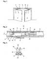
- Fig. 1 is a two-leaf door with a moving leaf 1 and a passive leaf 2 can be seen, with one above the door 1, 2 in or on the door frame arranged slide 9, in which the arranged on the slide arms 5, 6 of the door drives 3, 4 slides 7, 8 are guided. Furthermore, a release device 10 and a locking device 11 are arranged within the slide rail 9 for closing sequence control, which cooperate with the sliders 7, 8.
- the sliding arm 5 of the door drive 3 integrated in the moving leaf 1 executes a pivoting movement, which initially moves the slider 7 to the middle of the sliding rail and, in the event of further opening, in the direction of the door leaf strips.
- the triggering device 10 By opening the inactive leaf 2, the triggering device 10 via a transmission device 13, the locking device 11, not shown, whereby it blocks the open active leaf 1 in its direction of movement to the closed position.
- FIG. 2 shows a section of the slide rail 9 with the triggering device 10 arranged therein according to the invention in a sectional view.
- the triggering device 10 has a receptacle 12, in which the trigger slide 16, the latching element 19 and the clamping device 15 for the transmission element 13, for example a wire rope, are arranged.
- the transmission element 13 is fixed in the trigger slide 16, is guided over the guide roller 14 and cooperates with the locking device 11 for keeping the active leaf 1 open.
- the deflection roller 14 can be moved relative to the receptacle 12, whereby the transmission element 13 is tensioned.
- To the deflection roller 14 is fixed to a clamping element 22, which can be moved by a clamping screw 23 in the receptacle 12. It is advantageous that doubles the possible adjustment path for the transmission element 13 by the deflection of the transmission element 13 via the guide roller 14.
- the actuation of the locking device 11 is effected by a displacement movement of the trigger slide 16, which is spring-loaded, for example by a spring 11 arranged in the locking device 11 and the transmission element.
- the release slider 16 is fixed in its initial position, the closed position of the inactive leaf 2, guided by the locking element 19 guided in the receptacle 12, whereby the locking device 11 is in its release position, and whereby the active leaf is freely movable.
- this has one or more extensions 17, on each of which a holding element 18 is arranged.
- the holding element 18 may be a latching nose or a recess in the extension 17.
- the loaded in the direction of the extensions 17 by a spring 20 locking element 19 engages in the holding element 18, thereby preventing a sliding movement of the trigger slide 16.
- the slider 8 has a recessed area in which the extensions 17 and the latching element 19 project into and on which the triggering element 21 is arranged.
- the trip slider 16 can then move in the direction of the guide roller 14, which is blocked by the transmission member 13 and the locking device 11 of the active leaf.
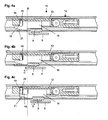
- FIGS. 4a to 4c is caused by the inactive leaf 2 sequence of movement of the slider 8 for actuating the locking device 11 is shown.
- the movement of the slider 8 and the trigger slider 16 can be seen from the line B, which is the same position in the FIGS. 4a to 4c features.
- the FIG. 4a shows the starting position in which the inactive leaf 2 is closed and the active leaf 1 can move freely. After opening the active leaf 1 the inactive leaf 2 can be opened, wherein the slider 8 first to the slide rail center, according to arrow C in FIG. 4b , emotional. In this case, the slider 8 arrives at its reversal point, wherein it is in contact with the release slide 16.
- the further opening of the passive leaf 2 now causes the direction reversal of the slider 8, according to arrow D in Fig. 4c , on the hinge side of the inactive leaf 2, whereby the locking element 19 runs onto the trigger element 21 and is lifted against the spring 20, and whereby the latching element 19 is disengaged from the retaining elements 18.
- the trip slider 16 can jump in the direction of the guide roller 14 move toward, with the transmission element 13 shifts and the locking device 11 is actuated to block the active leaf 1.
- An even further opening of the passive leaf 2 causes the slider 8 away from the trigger slide 16 after its maximum displacement movement, which may be determined by the bias of the transmission element 13 in the locking device 11, or even when the trigger slide within the receptacle 12 in a Stop position arrives. Due to the sudden displacement movement of the trigger slide 16 is a precise position for the onset of the effect of the locking device 11 in terms of the door opening angle possible.
- the design allows easy adjustment of the triggering device 10 by the receptacle 12, which can be fixed for example by clamping screws in the slide rail 9, is released, after which the inactive leaf is opened and the slider 8 through the release slider 16, the receptacle 12 in the position according to Fig. 4b shifts. Thereafter, the receptacle 12 is fixed in the slide rail 9 again, and the triggering device 10 is positioned.
Abstract
Description
Die Erfindung betrifft eine Vorrichtung zur Schließfolgeregelung nach dem Oberbegriff des Anspruchs 1.The invention relates to a device for closing sequence control according to the preamble of
Aus der
Nachteilig bei dieser Konstruktion ist es, dass die Gleitschiene eine Aussparung für die am Auslösehebel angeordnete Auslöserolle aufweisen muss, welche durch den Standflügel zur Freigabe der Klemmplatte beaufschlagt wird, wodurch die Schließfolgeregelung manipulierbar ist und nicht vollständig verdeckt im Türrahmen untergebracht ist. Die Justierbarkeit des Auslösepunkts des Auslösehebels durch die am Gleiter des Standflügels angeordnete Schubzunge ist schwierig.A disadvantage of this construction is that the slide must have a recess for the trigger roller arranged on the release roller, which is acted upon by the inactive leaf to release the clamping plate, whereby the closing sequence control is manipulated and not completely hidden in the door frame is housed. The adjustability of the trigger point of the release lever by the sliding tongue arranged on the slide of the passive leaf is difficult.
Aus der
Bei dieser Anordnung ist der Auslösepunkt für die Sperrvorrichtung durch die Freigabe des Auslösehebels nicht definiert. Möglicherweise könnte besonders bei schmalen Flügeln die Sperrung des Gangflügels zu spät erfolgen.In this arrangement, the trigger point for the locking device is not defined by the release of the release lever. Possibly, especially with narrow wings, the blocking of the active leaf could be too late.
Die
Aus der
In der
Der Erfindung liegt die Aufgabe zugrunde, eine Schließfolgeregelung auszubilden, wobei die Sperrvorrichtung des Gangflügels sicher betätigt wird.The invention has for its object to form a closing sequence control, wherein the locking device of the active leaf is operated safely.
Die Aufgabe wird durch die Merkmale des Anspruchs 1 gelöst.The object is solved by the features of
Die Unteransprüche bilden vorteilhafte Ausgestaltungsmöglichkeiten der Erfindung.The subclaims form advantageous embodiments of the invention.
Schließfolgeregelungen an mit Türantrieben versehenen zweiflügeligen Türen dienen dazu, den Standflügel vor dem mit einer Überlappung, dem Falz, versehenen Gangflügel, zu schließen. Werden Schließfolgeregelungen mit Gleitarm-Türantrieben verwendet, welche in den Türflügeln integriert oder auf der Bandgegenseite montiert sind, so bewegt sich der in der Gleitschiene geführte Gleiter zu Beginn der Öffnungsbewegung zunächst geringfügig zur Gleitschienenmitte und dann, nach Erreichen eines Umkehrpunktes, in Richtung des Türbands. Der standflügelseitige Gleiter betätigt eine Auslösevorrichtung, welche mit einer Sperrvorrichtung zusammenwirkt, welche auf den gangflügelseitigen Türschließer einwirkt. Dadurch wird das Schließen des Gangflügels verhindert, wenn sich der Standflügel in einer zumindest teilweise geöffneten Position befindet.Closing sequence controls on door-hinged double-leaf doors serve to close the inactive leaf in front of the topped leaf with an overlap. If closing sequence controls are used with Gleitarm door actuators, which are integrated in the door wings or mounted on the hinge opposite side, then the slider guided in the slide moves at the beginning of the opening movement initially slightly to the slide rail center and then, after reaching a turning point, in the direction of the door hinge. The stand-wing-side slider actuates a triggering device which cooperates with a locking device which acts on the gangway-side door closer. As a result, the closing of the active leaf is prevented when the inactive leaf is in an at least partially open position.
Die Auslösevorrichtung weist einen Schieber und ein Rastelement auf, wodurch, trotz der gegenläufigen Bewegung des Gleiters zu Beginn der Öffnungsbewegung des Standflügels, der Auslösepunkt für die Sperrung des Gangflügels in Abhängigkeit vom Öffnungswinkel des Standflügels festgelegt ist.The triggering device has a slide and a locking element, whereby, despite the opposite movement of the slider at the beginning of the opening movement of the passive leaf, the trigger point for the blocking of the active leaf is determined in dependence on the opening angle of the passive leaf.
Im Nachfolgenden wird ein Ausführungsbeispiel in der Zeichnung anhand der Figuren näher erläutert.In the following an embodiment in the drawing with reference to the figures will be explained in more detail.
Dabei zeigen:
- Fig. 1
- eine zweiflügelige Tür mit einer Schließfolgeregelung und mit in den Türflügeln integrierten Türantrieben;
- Fig. 2
- einen Ausschnitt der in der Gleitschiene angeordneten Auslösevorrichtung in geschnittener Darstellung;
- Fig. 3
- eine Ansicht gemäß Pfeil A in
Fig. 2 auf das Rastelement und die Fortsätze der Auslösevorrichtung; - Fig. 4a
- eine Ansicht der Auslösevorrichtung gemäß
Fig. 2 , wobei sich der Standflügel in seiner Geschlossenlage befindet; - Fig. 4b
- die Ansicht gemäß
Fig. 4a , wobei sich der Gleiter zu Beginn der Öffnungsbewegung des Standflügels am Umkehrpunkt befindet; - Fig. 4c
- die Ansicht gemäß
Fig. 4b , mit weiter geöffnetem Standflügel, wobei die Auslöseposition für die gangflügelseitige Sperrvorrichtung erreicht ist.
- Fig. 1
- a double-leaf door with a closing sequence control and door operators integrated in the door leaves;
- Fig. 2
- a section of the arranged in the slide release device in a sectional view;
- Fig. 3
- a view according to arrow A in
Fig. 2 on the locking element and the extensions of the triggering device; - Fig. 4a
- a view of the triggering device according to
Fig. 2 , wherein the inactive leaf is in its closed position; - Fig. 4b
- the view according to
Fig. 4a , wherein the slider is at the reversal point at the beginning of the opening movement of the passive leaf; - Fig. 4c
- the view according to
Fig. 4b , with further open inactive leaf, wherein the triggering position is achieved for the gangway-side locking device.
Aus der
Durch Öffnen des Gangflügels 1 führt der Gleitarm 5 des im Gangflügel 1 integrierten Türantriebs 3 eine Schwenkbewegung aus, die den Gleiter 7 zunächst zur Gleitschienenmitte und bei weiterem Öffnen in Richtung der Türflügelbänder bewegt. Nach Öffnen des Gangflügels 1 kann der Standflügel 2 geöffnet werden, wobei der Gleitarm 6 des im Standflügel 2 integrierten Türantriebs 4 eine Schwenkbewegung durchführt, welche den Gleiter 8 ebenfalls zunächst zur Gleitschienenmitte und bei weiterem Öffnen des Standflügels 2 in Richtung der Türflügelbänder bewegt. Dieser Bewegungsablauf, bei dem der Gleiter 7, 8 zu Beginn der Öffnungsbewegung zunächst zur Gleitschienenmitte und bei weiterem Öffnen der Türflügel 1, 2 in Richtung der Türbänder bewegt wird, tritt bei im Flügel 1, 2 integrierten Türantrieben 3, 4 und bei der Montage von Türantrieben 3, 4 auf der Bandgegenseite auf.From the
By opening the
Durch das Öffnen des Standflügels 2 betätigt die Auslösevorrichtung 10 über eine Übertragungseinrichtung 13 die nicht näher dargestellte Sperrvorrichtung 11, wodurch diese den geöffneten Gangflügel 1 in seiner Bewegungsrichtung auf die Geschlossenlage hin sperrt.By opening the
Die
Durch die Spanneinrichtung 15 kann die Umlenkrolle 14 relativ zur Aufnahme 12 verschoben werden, wodurch das Übertragungselement 13 gespannt wird. Dazu ist die Umlenkrolle 14 an einem Spannelement 22 festgelegt, welches durch eine Spannschraube 23 in der Aufnahme 12 verschoben werden kann. Vorteilhaft ist, dass durch die Umlenkung des Übertragungselements 13 über die Umlenkrolle 14 sich der mögliche Einstellweg für das Übertragungselement 13 verdoppelt.By the
Die Betätigung der Sperrvorrichtung 11 erfolgt durch eine Verschiebebewegung des Auslöseschiebers 16, welcher beispielsweise durch eine in der Sperrvorrichtung 11 angeordnete Feder und das Übertragungselement 13 federbelastet ist. Der Auslöseschieber 16 ist in seiner Ausgangslage, der Geschlossenlage des Standflügels 2, durch das in der Aufnahme 12 geführte Rastelement 19 fixiert, wodurch die Sperrvorrichtung 11 in ihrer Freigabestellung ist, und wodurch der Gangflügel frei bewegbar ist. Zur Fixierung des Auslöseschiebers 16 weist dieser einen oder mehrere Fortsätze 17 auf, an welchen jeweils ein Halteelement 18 angeordnet ist. Das Halteelement 18 kann eine Rastnase oder eine Vertiefung im Fortsatz 17 sein. Das in Richtung auf die Fortsätze 17 durch eine Feder 20 belastete Rastelement 19 greift in das Halteelement 18 ein und verhindert damit eine Verschiebebewegung des Auslöseschiebers 16. Wie es aus den
In den
Beim Schließen des Standflügels 2 bewegt sich der Gleiter 8 wieder auf den Auslöseschieber 16 zu und gelangt erneut in Anlage mit diesem, gemäß der Position in
Die Konstruktion erlaubt ein einfaches Einstellen der Auslöseeinrichtung 10, indem die Aufnahme 12, welche beispielsweise durch Klemmschrauben in der Gleitschiene 9 festsetzbar ist, gelöst wird, wonach der Standflügel geöffnet wird und der Gleiter 8 durch den Auslöseschieber 16 die Aufnahme 12 in die Position gemäß
- 11
- Gangflügelleaf
- 22
- StandflügelFixed leaf
- 33
- gangflügelseitiger TürantriebWing-side door drive
- 44
- standflügelseitiger Türantriebdoor leaf-side door drive
- 55
- Gleitarm gangflügelseitiger TürantriebSliding arm wing-side door drive
- 66
- Gleitarm standflügelseitiger TürantriebSliding arm on the door leaf side door drive
- 77
- gangflügelseitiger Gleiterpasser-side glider
- 88th
- standflügelseitiger Gleiterfeather-side glider
- 99
- Gleitschieneslide
- 1010
- Auslösevorrichtungtriggering device
- 1111
- Sperrvorrichtunglocking device
- 1212
- Aufnahmeadmission
- 1313
- Übertragungselementtransmission element
- 1414
- Umlenkrolleidler pulley
- 1515
- Spanneinrichtungtensioning device
- 1616
- Auslöseschiebertrip slider
- 1717
- Fortsatzextension
- 1818
- Halteelementretaining element
- 1919
- Rastelementlocking element
- 2020
- elastisches Elementelastic element
- 2121
- Auslöseelementtriggering element
- 2222
- Spannelementclamping element
- 2323
- Spannschraubeclamping screw
Claims (14)
- Arrangement for controlling the closing sequence of double-leaf swing doors, having a passive leaf (2) and an active leaf (1), which are provided with door drives (3, 4), wherein at least the passive-leaf door drive (4) engages in a sliding rail (9) via a sliding arm (6) and a slider (8), furthermore having a release arrangement (10) that can be actuated by the passive leaf (2), and having a transmission element (13) which is connected to a blocking arrangement (11) of the arrangement controlling the closing sequence, said blocking arrangement (11) interacting with the door drive (3) of the active leaf (1), characterized
in that at the start of an opening movement of the passive leaf (2), the passive-leaf slider (8) first of all moves to the middle of the sliding rail, wherein the passive-leaf slider (8) has a recessed region, into which there project a release slide (16), which is arranged in the release arrangement (10) and is spring-loaded by the blocking arrangement (11), and a spring-loaded latching element (19) of the release arrangement, wherein the release slide (16) is in engagement with a retaining element (18) having the spring-loaded latching element (19), as a result of which the release slide (16) is fixed and the blocking arrangement (11) is in its released position, in which the active leaf (1) can move freely,
and in that, while the passive leaf (2) continues to open, the movement of the slider (8) in the direction of the door hinges releases the latching element (19) in order to actuate the blocking arrangement (11) in order to secure the active leaf (1) and abruptly releases the release slide (16) in that a release element (21) on the passive-leaf slider (8) moves the latching element (19) against a spring (20) and the latching element (19) comes out of engagement with the retaining element (18) of the release slide (16). - Arrangement according to Claim 1, characterized in that the latching element (19) is formed as a slide, which is moved by the slider (8).
- Arrangement according to Claim 1, characterized in that on the release slide (16) there is formed at least one extension (17), which interacts with the latching element (19).
- Arrangement according to Claim 3, characterized in that the retaining elements (18) are formed on an extension (17) of the release slide (16).
- Arrangement according to Claim 1, characterized in that the latching element (19) is forced by an elastic element (20) in the direction of its position locking the release slide (16).
- Arrangement according to Claim 1, characterized in that the slider (8) has a release element (21) which actuates the latching element (19) in order to release the release slide (16).
- Arrangement according to Claim 1,
characterized in that the release slide (16) is operatively connected to the blocking means (11) via a transmission element (13). - Arrangement according to Claim 7,
characterized in that the transmission element (13) is a flexible element and is deflected in its direction of action. - Arrangement according to Claim 8,
characterized in that the flexible element is deflected through 180° into the opposite direction of action. - Arrangement according to Claim 8,
characterized in that the transmission element (13) is deflected via a deflection roller (14). - Arrangement according to Claim 10,
characterized in that the release arrangement (10) has a clamping device (15) having a clamping means (22), on which the deflection roller (14) is arranged. - Arrangement according to Claim 11,
characterized in that the clamping element (22) is movably guided in the holder (12) together with the deflection roller (14). - Arrangement according to Claim 12,
characterized in that the tension in the transmission element (13) can be set by the movement of the deflection roller (14). - Arrangement according to Claim 13,
characterized in that the clamping device (15) has a clamping screw (22) for setting the tension in the transmission element (13).
Applications Claiming Priority (2)
| Application Number | Priority Date | Filing Date | Title |
|---|---|---|---|
| DE10360039 | 2003-12-18 | ||
| DE10360039A DE10360039B4 (en) | 2003-12-18 | 2003-12-18 | Device for closing sequence control for double-leaf revolving doors |
Publications (4)
| Publication Number | Publication Date |
|---|---|
| EP1544395A2 EP1544395A2 (en) | 2005-06-22 |
| EP1544395A3 EP1544395A3 (en) | 2009-04-22 |
| EP1544395B1 true EP1544395B1 (en) | 2011-11-02 |
| EP1544395B8 EP1544395B8 (en) | 2012-03-21 |
Family
ID=34485537
Family Applications (1)
| Application Number | Title | Priority Date | Filing Date |
|---|---|---|---|
| EP04028652A Active EP1544395B8 (en) | 2003-12-18 | 2004-12-03 | Door-closing selector device for double-leave doors |
Country Status (4)
| Country | Link |
|---|---|
| EP (1) | EP1544395B8 (en) |
| AT (1) | ATE531886T1 (en) |
| DE (1) | DE10360039B4 (en) |
| ES (1) | ES2374519T3 (en) |
Families Citing this family (2)
| Publication number | Priority date | Publication date | Assignee | Title |
|---|---|---|---|---|
| EP1801336A1 (en) * | 2005-12-22 | 2007-06-27 | GEZE GmbH | Door-closing selector |
| AT515398A1 (en) * | 2014-01-29 | 2015-08-15 | Walter Ing Degelsegger | Device for controlling the closing sequence of double-leaf swing doors |
Family Cites Families (7)
| Publication number | Priority date | Publication date | Assignee | Title |
|---|---|---|---|---|
| DE8810389U1 (en) | 1988-08-17 | 1988-09-29 | Gretsch-Unitas Gmbh Baubeschlaege, 7257 Ditzingen, De | |
| DE29501776U1 (en) | 1995-02-07 | 1995-04-13 | Dorma Gmbh & Co Kg | Closing sequence control for a double-leaf door |
| DE19605744A1 (en) * | 1995-09-07 | 1997-03-13 | Geze Gmbh & Co | Opening and closure sequence control device for pair of swing doors |
| DE19545402A1 (en) * | 1995-12-06 | 1997-06-12 | Geze Gmbh & Co | Closing sequence control for automatically closing two-leaf doors |
| DE19545401A1 (en) * | 1995-12-06 | 1997-06-12 | Geze Gmbh & Co | Closing sequence control for automatically closing double-panel door |
| DE19855425B4 (en) * | 1998-12-02 | 2014-02-06 | Ernst Schulte | Closing sequence control device for a double-leaf door |
| FI107634B (en) * | 2000-02-18 | 2001-09-14 | Abloy Oy | Door closure arrangement for double doors |
-
2003
- 2003-12-18 DE DE10360039A patent/DE10360039B4/en not_active Expired - Lifetime
-
2004
- 2004-12-03 ES ES04028652T patent/ES2374519T3/en active Active
- 2004-12-03 AT AT04028652T patent/ATE531886T1/en active
- 2004-12-03 EP EP04028652A patent/EP1544395B8/en active Active
Also Published As
| Publication number | Publication date |
|---|---|
| DE10360039B4 (en) | 2009-06-18 |
| ATE531886T1 (en) | 2011-11-15 |
| EP1544395B8 (en) | 2012-03-21 |
| ES2374519T3 (en) | 2012-02-17 |
| EP1544395A3 (en) | 2009-04-22 |
| DE10360039A1 (en) | 2005-07-28 |
| EP1544395A2 (en) | 2005-06-22 |
Similar Documents
| Publication | Publication Date | Title |
|---|---|---|
| EP0726379B1 (en) | Double doors with controlled order of closing | |
| EP0141902B1 (en) | Device for controlling the closure sequence of double doors | |
| DE2920581C2 (en) | Additional locking, in particular central locking, for windows, doors or the like. | |
| EP1500766A2 (en) | Bifold flap or door lifting apparatus | |
| DE60111286T2 (en) | Door closing arrangement for double doors | |
| EP1544394B1 (en) | Device for holding a wing, particularly of a door or window | |
| EP0324075B1 (en) | Device for controlling the closure sequence of double-wing doors | |
| EP0452710B1 (en) | Closure sequence control device for a double-wing door | |
| EP1544395B1 (en) | Door-closing selector device for double-leave doors | |
| EP1544398B1 (en) | Door-closing selector device for double-leave doors | |
| EP1612358B1 (en) | Closure sequence controller for a double-wing door | |
| DE102009031490A1 (en) | Closing sequence regulating device for two-winged door, has releasing device actuated by passive door wing, and helical compression spring loading blocking device with adjustment force until blocking stop reaches holding position | |
| EP1096088B1 (en) | Closing sequence control with a locking device activated by a standing panel | |
| DE202004004341U1 (en) | Hinge mechanism for connecting door leaf to door frame has first set of hinge bands with pivots in frame sliding in grooves in door leaf and second set of bands pivoting on leaf and sliding in frame | |
| EP1147278B1 (en) | Locking device for the overlapped wing of two-wing windows, doors or such like not having central posts | |
| DE10111732A1 (en) | Closing follower for a two-leaf, self-closing door comprises a locking mechanism arranged in a guide rail | |
| DE3609565C2 (en) | Closing sequence control device for a double-leaf door | |
| EP0985794A2 (en) | Drive for a wing of a door, a window or the like | |
| EP1544396B1 (en) | Closure sequence controller for a double-wing door | |
| DE102012220079B3 (en) | Closing sequence control device for door closer for two-wing doors, has locking device with bearing ring arranged in lock housing, and locking bodies provided between bearing ring and output shaft directly or indirectly clamped on periphery | |
| EP1544397A2 (en) | Blocking device for a wing of a door or window | |
| DE149998C (en) | ||
| DE19520231A1 (en) | Garage door drive with floor-parallel guide rail | |
| DE10107884B4 (en) | Door coordinator | |
| EP2090730B1 (en) | Locking device |
Legal Events
| Date | Code | Title | Description |
|---|---|---|---|
| PUAI | Public reference made under article 153(3) epc to a published international application that has entered the european phase |
Free format text: ORIGINAL CODE: 0009012 |
|
| AK | Designated contracting states |
Kind code of ref document: A2 Designated state(s): AT BE BG CH CY CZ DE DK EE ES FI FR GB GR HU IE IS IT LI LT LU MC NL PL PT RO SE SI SK TR |
|
| AX | Request for extension of the european patent |
Extension state: AL BA HR LV MK YU |
|
| PUAL | Search report despatched |
Free format text: ORIGINAL CODE: 0009013 |
|
| AK | Designated contracting states |
Kind code of ref document: A3 Designated state(s): AT BE BG CH CY CZ DE DK EE ES FI FR GB GR HU IE IS IT LI LT LU MC NL PL PT RO SE SI SK TR |
|
| AX | Request for extension of the european patent |
Extension state: AL BA HR LV MK YU |
|
| 17P | Request for examination filed |
Effective date: 20090924 |
|
| 17Q | First examination report despatched |
Effective date: 20091105 |
|
| AKX | Designation fees paid |
Designated state(s): AT BE BG CH CY CZ DE DK EE ES FI FR GB GR HU IE IS IT LI LT LU MC NL PL PT RO SE SI SK TR |
|
| GRAP | Despatch of communication of intention to grant a patent |
Free format text: ORIGINAL CODE: EPIDOSNIGR1 |
|
| GRAS | Grant fee paid |
Free format text: ORIGINAL CODE: EPIDOSNIGR3 |
|
| GRAA | (expected) grant |
Free format text: ORIGINAL CODE: 0009210 |
|
| AK | Designated contracting states |
Kind code of ref document: B1 Designated state(s): AT BE BG CH CY CZ DE DK EE ES FI FR GB GR HU IE IS IT LI LT LU MC NL PL PT RO SE SI SK TR |
|
| REG | Reference to a national code |
Ref country code: GB Ref legal event code: FG4D Free format text: NOT ENGLISH |
|
| REG | Reference to a national code |
Ref country code: CH Ref legal event code: EP |
|
| RBV | Designated contracting states (corrected) |
Designated state(s): AT BE BG CH CY CZ DK EE ES FI FR GB GR HU IE IS IT LI LT LU MC NL PL PT RO SE SI SK TR |
|
| REG | Reference to a national code |
Ref country code: IE Ref legal event code: FG4D |
|
| REG | Reference to a national code |
Ref country code: DE Ref legal event code: R096 Ref document number: 502004013022 Country of ref document: DE Effective date: 20120105 Ref country code: DE Ref legal event code: R108 Ref document number: 502004013022 Country of ref document: DE Effective date: 20111117 |
|
| REG | Reference to a national code |
Ref country code: ES Ref legal event code: FG2A Ref document number: 2374519 Country of ref document: ES Kind code of ref document: T3 Effective date: 20120217 |
|
| REG | Reference to a national code |
Ref country code: NL Ref legal event code: VDEP Effective date: 20111102 |
|
| LTIE | Lt: invalidation of european patent or patent extension |
Effective date: 20111102 |
|
| PG25 | Lapsed in a contracting state [announced via postgrant information from national office to epo] |
Ref country code: LT Free format text: LAPSE BECAUSE OF FAILURE TO SUBMIT A TRANSLATION OF THE DESCRIPTION OR TO PAY THE FEE WITHIN THE PRESCRIBED TIME-LIMIT Effective date: 20111102 Ref country code: IS Free format text: LAPSE BECAUSE OF FAILURE TO SUBMIT A TRANSLATION OF THE DESCRIPTION OR TO PAY THE FEE WITHIN THE PRESCRIBED TIME-LIMIT Effective date: 20120302 |
|
| PG25 | Lapsed in a contracting state [announced via postgrant information from national office to epo] |
Ref country code: PL Free format text: LAPSE BECAUSE OF FAILURE TO SUBMIT A TRANSLATION OF THE DESCRIPTION OR TO PAY THE FEE WITHIN THE PRESCRIBED TIME-LIMIT Effective date: 20111102 Ref country code: PT Free format text: LAPSE BECAUSE OF FAILURE TO SUBMIT A TRANSLATION OF THE DESCRIPTION OR TO PAY THE FEE WITHIN THE PRESCRIBED TIME-LIMIT Effective date: 20120302 Ref country code: NL Free format text: LAPSE BECAUSE OF FAILURE TO SUBMIT A TRANSLATION OF THE DESCRIPTION OR TO PAY THE FEE WITHIN THE PRESCRIBED TIME-LIMIT Effective date: 20111102 Ref country code: SI Free format text: LAPSE BECAUSE OF FAILURE TO SUBMIT A TRANSLATION OF THE DESCRIPTION OR TO PAY THE FEE WITHIN THE PRESCRIBED TIME-LIMIT Effective date: 20111102 Ref country code: GR Free format text: LAPSE BECAUSE OF FAILURE TO SUBMIT A TRANSLATION OF THE DESCRIPTION OR TO PAY THE FEE WITHIN THE PRESCRIBED TIME-LIMIT Effective date: 20120203 Ref country code: SE Free format text: LAPSE BECAUSE OF FAILURE TO SUBMIT A TRANSLATION OF THE DESCRIPTION OR TO PAY THE FEE WITHIN THE PRESCRIBED TIME-LIMIT Effective date: 20111102 |
|
| REG | Reference to a national code |
Ref country code: IE Ref legal event code: FD4D |
|
| PG25 | Lapsed in a contracting state [announced via postgrant information from national office to epo] |
Ref country code: CY Free format text: LAPSE BECAUSE OF FAILURE TO SUBMIT A TRANSLATION OF THE DESCRIPTION OR TO PAY THE FEE WITHIN THE PRESCRIBED TIME-LIMIT Effective date: 20111102 |
|
| BERE | Be: lapsed |
Owner name: GEZE G.M.B.H. Effective date: 20111231 |
|
| PG25 | Lapsed in a contracting state [announced via postgrant information from national office to epo] |
Ref country code: SK Free format text: LAPSE BECAUSE OF FAILURE TO SUBMIT A TRANSLATION OF THE DESCRIPTION OR TO PAY THE FEE WITHIN THE PRESCRIBED TIME-LIMIT Effective date: 20111102 Ref country code: CZ Free format text: LAPSE BECAUSE OF FAILURE TO SUBMIT A TRANSLATION OF THE DESCRIPTION OR TO PAY THE FEE WITHIN THE PRESCRIBED TIME-LIMIT Effective date: 20111102 Ref country code: DK Free format text: LAPSE BECAUSE OF FAILURE TO SUBMIT A TRANSLATION OF THE DESCRIPTION OR TO PAY THE FEE WITHIN THE PRESCRIBED TIME-LIMIT Effective date: 20111102 Ref country code: IE Free format text: LAPSE BECAUSE OF FAILURE TO SUBMIT A TRANSLATION OF THE DESCRIPTION OR TO PAY THE FEE WITHIN THE PRESCRIBED TIME-LIMIT Effective date: 20111102 Ref country code: EE Free format text: LAPSE BECAUSE OF FAILURE TO SUBMIT A TRANSLATION OF THE DESCRIPTION OR TO PAY THE FEE WITHIN THE PRESCRIBED TIME-LIMIT Effective date: 20111102 Ref country code: MC Free format text: LAPSE BECAUSE OF NON-PAYMENT OF DUE FEES Effective date: 20111231 Ref country code: BG Free format text: LAPSE BECAUSE OF FAILURE TO SUBMIT A TRANSLATION OF THE DESCRIPTION OR TO PAY THE FEE WITHIN THE PRESCRIBED TIME-LIMIT Effective date: 20120202 |
|
| PG25 | Lapsed in a contracting state [announced via postgrant information from national office to epo] |
Ref country code: RO Free format text: LAPSE BECAUSE OF FAILURE TO SUBMIT A TRANSLATION OF THE DESCRIPTION OR TO PAY THE FEE WITHIN THE PRESCRIBED TIME-LIMIT Effective date: 20111102 |
|
| PLBE | No opposition filed within time limit |
Free format text: ORIGINAL CODE: 0009261 |
|
| REG | Reference to a national code |
Ref country code: FR Ref legal event code: ST Effective date: 20120831 |
|
| STAA | Information on the status of an ep patent application or granted ep patent |
Free format text: STATUS: NO OPPOSITION FILED WITHIN TIME LIMIT |
|
| 26N | No opposition filed |
Effective date: 20120803 |
|
| PG25 | Lapsed in a contracting state [announced via postgrant information from national office to epo] |
Ref country code: BE Free format text: LAPSE BECAUSE OF NON-PAYMENT OF DUE FEES Effective date: 20111231 |
|
| PG25 | Lapsed in a contracting state [announced via postgrant information from national office to epo] |
Ref country code: FR Free format text: LAPSE BECAUSE OF NON-PAYMENT OF DUE FEES Effective date: 20120102 |
|
| PG25 | Lapsed in a contracting state [announced via postgrant information from national office to epo] |
Ref country code: LU Free format text: LAPSE BECAUSE OF NON-PAYMENT OF DUE FEES Effective date: 20111203 |
|
| PG25 | Lapsed in a contracting state [announced via postgrant information from national office to epo] |
Ref country code: TR Free format text: LAPSE BECAUSE OF FAILURE TO SUBMIT A TRANSLATION OF THE DESCRIPTION OR TO PAY THE FEE WITHIN THE PRESCRIBED TIME-LIMIT Effective date: 20111102 |
|
| PG25 | Lapsed in a contracting state [announced via postgrant information from national office to epo] |
Ref country code: HU Free format text: LAPSE BECAUSE OF FAILURE TO SUBMIT A TRANSLATION OF THE DESCRIPTION OR TO PAY THE FEE WITHIN THE PRESCRIBED TIME-LIMIT Effective date: 20111102 |
|
| REG | Reference to a national code |
Ref country code: DE Ref legal event code: R107 Ref document number: 502004013022 Country of ref document: DE |
|
| PGFP | Annual fee paid to national office [announced via postgrant information from national office to epo] |
Ref country code: GB Payment date: 20221222 Year of fee payment: 19 Ref country code: FI Payment date: 20221222 Year of fee payment: 19 Ref country code: AT Payment date: 20221222 Year of fee payment: 19 |
|
| PGFP | Annual fee paid to national office [announced via postgrant information from national office to epo] |
Ref country code: ES Payment date: 20230224 Year of fee payment: 19 Ref country code: CH Payment date: 20221213 Year of fee payment: 19 |
|
| PGFP | Annual fee paid to national office [announced via postgrant information from national office to epo] |
Ref country code: IT Payment date: 20221228 Year of fee payment: 19 |