EP0452710B1 - Closure sequence control device for a double-wing door - Google Patents
Closure sequence control device for a double-wing door Download PDFInfo
- Publication number
- EP0452710B1 EP0452710B1 EP91104718A EP91104718A EP0452710B1 EP 0452710 B1 EP0452710 B1 EP 0452710B1 EP 91104718 A EP91104718 A EP 91104718A EP 91104718 A EP91104718 A EP 91104718A EP 0452710 B1 EP0452710 B1 EP 0452710B1
- Authority
- EP
- European Patent Office
- Prior art keywords
- slider
- leaf
- door
- wedge
- shaped part
- Prior art date
- Legal status (The legal status is an assumption and is not a legal conclusion. Google has not performed a legal analysis and makes no representation as to the accuracy of the status listed.)
- Expired - Lifetime
Links
Images


Classifications
-
- E—FIXED CONSTRUCTIONS
- E05—LOCKS; KEYS; WINDOW OR DOOR FITTINGS; SAFES
- E05F—DEVICES FOR MOVING WINGS INTO OPEN OR CLOSED POSITION; CHECKS FOR WINGS; WING FITTINGS NOT OTHERWISE PROVIDED FOR, CONCERNED WITH THE FUNCTIONING OF THE WING
- E05F5/00—Braking devices, e.g. checks; Stops; Buffers
- E05F5/12—Braking devices, e.g. checks; Stops; Buffers specially for preventing the closing of a wing before another wing has been closed
-
- E—FIXED CONSTRUCTIONS
- E05—LOCKS; KEYS; WINDOW OR DOOR FITTINGS; SAFES
- E05F—DEVICES FOR MOVING WINGS INTO OPEN OR CLOSED POSITION; CHECKS FOR WINGS; WING FITTINGS NOT OTHERWISE PROVIDED FOR, CONCERNED WITH THE FUNCTIONING OF THE WING
- E05F3/00—Closers or openers with braking devices, e.g. checks; Construction of pneumatic or liquid braking devices
- E05F3/16—Closers or openers with braking devices, e.g. checks; Construction of pneumatic or liquid braking devices with friction brakes
-
- E—FIXED CONSTRUCTIONS
- E05—LOCKS; KEYS; WINDOW OR DOOR FITTINGS; SAFES
- E05F—DEVICES FOR MOVING WINGS INTO OPEN OR CLOSED POSITION; CHECKS FOR WINGS; WING FITTINGS NOT OTHERWISE PROVIDED FOR, CONCERNED WITH THE FUNCTIONING OF THE WING
- E05F3/00—Closers or openers with braking devices, e.g. checks; Construction of pneumatic or liquid braking devices
- E05F3/22—Additional arrangements for closers, e.g. for holding the wing in opened or other position
- E05F3/227—Additional arrangements for closers, e.g. for holding the wing in opened or other position mounted at the top of wings, e.g. details related to closer housings, covers, end caps or rails therefor
-
- E—FIXED CONSTRUCTIONS
- E05—LOCKS; KEYS; WINDOW OR DOOR FITTINGS; SAFES
- E05Y—INDEXING SCHEME RELATING TO HINGES OR OTHER SUSPENSION DEVICES FOR DOORS, WINDOWS OR WINGS AND DEVICES FOR MOVING WINGS INTO OPEN OR CLOSED POSITION, CHECKS FOR WINGS AND WING FITTINGS NOT OTHERWISE PROVIDED FOR, CONCERNED WITH THE FUNCTIONING OF THE WING
- E05Y2201/00—Constructional elements; Accessories therefore
- E05Y2201/60—Suspension or transmission members; Accessories therefore
- E05Y2201/622—Suspension or transmission members elements
- E05Y2201/686—Rods, links
-
- E—FIXED CONSTRUCTIONS
- E05—LOCKS; KEYS; WINDOW OR DOOR FITTINGS; SAFES
- E05Y—INDEXING SCHEME RELATING TO HINGES OR OTHER SUSPENSION DEVICES FOR DOORS, WINDOWS OR WINGS AND DEVICES FOR MOVING WINGS INTO OPEN OR CLOSED POSITION, CHECKS FOR WINGS AND WING FITTINGS NOT OTHERWISE PROVIDED FOR, CONCERNED WITH THE FUNCTIONING OF THE WING
- E05Y2900/00—Application of doors, windows, wings or fittings thereof
- E05Y2900/10—Application of doors, windows, wings or fittings thereof for buildings or parts thereof
- E05Y2900/13—Application of doors, windows, wings or fittings thereof for buildings or parts thereof characterised by the type of wing
- E05Y2900/132—Doors
Definitions
- the invention relates to a closing sequence control device according to the preamble of claim 1.
- Corresponding two-wing doors usually overlap each other in the central region, so that the door wing forming a fixed leaf has a stop for the other door leaf forming the active leaf.
- a closing sequence is necessary which ensures that the opened passive leaf leads the active leaf, i.e. the passive leaf in front of the active leaf is closed.
- a closing sequence control device according to the preamble of claim 1 is known from DE 36 04 091 A1, which is a further development of the device according to DE 33 36 739 C2.
- the active leaf When the passive leaf is fully or partially open, the active leaf can be freely actuated in the opening direction, but when the active leaf is loaded in the closing direction, a locking device acts which is released by actuating the active leaf shortly before reaching its closed position and allows the active leaf to be closed. However, it is also ensured that when the passive leaf is open and an overload occurs on the active leaf, it can be moved against the locking device in the closing direction in order to prevent destruction of the door closer or the associated lever linkage as a result of the high moments that occur. In this closing sequence control device known from DE 36 04 091 A 1, the two door leaves can each be moved by a door closer acting in the closing direction.
- the ends of the associated swivel arms of the door closers on the door frame side can each be displaced with a slide piece in a slide guide horizontally attached to the door frame.
- the passive leaf-side slide acts against a slide bolt mounted in the guide rail, via which a locking member, which controls the active leaf side, can be ascertained and released by a control member designed as an axially displaceable clamping rod.
- a clamping plate designed as a locking member and encompassing the sliding bar, longitudinally displaceable clamping rod is supported spring-loaded on the one hand on a spring bearing which can be moved from the passive leaf into the release position and on the other hand on an overload member guided on the clamping rod
- Overload member is held on the one hand via a spring member yielding in the event of an overload on a stationary stop member.
- Such a closing sequence control is relatively complex.
- the clamping plate used acts by tilting against the clamping rods, so that it is damaged in frequent use to damage the clamping plate or the clamping rod the kind of so-called chatter marks can come.
- the invention has for its object to simplify a closing sequence control device for a two-leaf door according to the preamble of claim 1 and to increase its operational reliability.
- a particularly advantageous torque-locking connection of the passive leaf-side slider with the square rod is specified in claim 2.
- the locking device on the active leaf side is proposed according to claims 3, 4, 5 and 6.
- Such a locking device simultaneously forms an overload protection device in the manner of a slip clutch.
- the frictional force of the locking device on the inside of the guide rail is overcome, so that the active leaf can be moved despite locking.
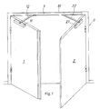
- the open passive leaf is designated by the number 1 and the also open active leaf by the number 2.
- Both door leaves are hinged to the door frame 8.
- the two leaves 1 and 2 are equipped with door closers 11 and 21, respectively.
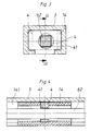
- Your articulated swivel arms 12 and 22 slide with slide pieces 14 and 24 on the door frame side, which can be seen in FIG. 2, in a cross-sectionally C-shaped guide rail 3 on the upper door frame frame 81.
- the axes of rotation between the slide pieces 14 and 24 and the swivel arms 12 and 22 are indicated by the numbers 13 and 23.
- the two sliding pieces 14 and 24 are connected to the closing sequence control via a square rod 6 serving as a control element or a corresponding, in principle, non-circular, other rod.
- This square rod 6 has a transition piece 61 twisted approximately in the middle by approximately 45 °.
- the ends of the square rod 6 are designated by the numbers 62 and 63, respectively.
- This square rod 6 is rotatable and fixed in the axial direction in the guide rail 3.
- the end 62 is torque-locked in the leaf-side slide 14.
- the end 63 penetrates the slider 24 on the active leaf side.
- the fixed wing-side slide piece 14 which consists for example of a slidable plastic, is received in a form-fitting manner in the guide rail 3.
- a relatively narrow guide piece 4 for example made of metal, is used with the opening 41 in a square shape corresponding to the cross section of the end 62 of the square rod 6.
- the slide piece 14 is pierced in a cylindrical shape. The bore bears the number 141.
- the position of the slide piece 14 corresponds to the open position of the passive leaf 1 in FIG. 1.
- the slide piece 14 is located to the left of the transition piece 61 of the square rod 6. In this position, the other end 63 is rotated 45 ° relative to the end 62. If the inactive leaf 1 is brought into the closed position, the slide piece 14 with the guide piece 4 accommodated therein is pushed over the transition piece 61 of the square rod 6 twisted by 45 ° and rotated by 45 °. The slider is then in the position indicated by dashed lines in Figure 8.
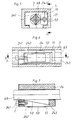
- the other end 63 of the square rod 6 penetrates with play the through cylindrical bore 241 in the sliding leaf 24 on the active leaf side 6 or the end 62 is actuated from the passive leaf 1.
- a chamber 242 which is open towards the side wall 31 of the guide rail 3 and which accommodates two wedge pieces 51 and 52 adjacent to one another is formed in the slide piece 24.
- the outer wedge piece 51 has a friction lining 53 on the side facing the side wall 31. As can be seen in particular from FIG. 7, this wedge piece 51 can be displaced to a limited extent into a free space 243 in the sliding piece 24. The displacement of this wedge piece 51 can be set up via the adjustable head screw 7 screwed into the wedge piece 51.
- the outwardly projecting head 71 limits this path.
- the inner wedge piece 52 protrudes into the bore 241 of the slide piece 24 and is in any rotational position at the end 62 of the square rod 6.
- the shaft of the cap screw 7 is guided through the smooth bore 241 of the slider 24.
- the end 62 of the square rod 6 is rotated by 45 °, so that a flat side of the end 62 rests on the wedge piece 52 and the friction lining 53 on the outer wedge piece 51 is only under slight pressure the side wall 31 presses.
- the slider 24 is in principle freely movable on the end 62.
- a setting can be achieved by appropriate dimensions in which the active leaf 2 remains in any open position due to a slight braking force between the friction lining 53 and the side wall 31.
Description
Die Erfindung betrifft eine Schließfolgeregelvorrichtung nach dem Oberbegriff des Anspruches 1. Entsprechende zweiflügelige Türen überlappen einander in der Regel im Mittelbereich, so daß der eine einen Standflügel bildende Türflügel einen Anschlag für den anderen, den Gangflügel bildenden Türflügel aufweist. Um die Türflügel ordnungsgemäß zu schließen, ist eine Schließfolge notwendig, die sicherstellt, daß der geöffnete Standflügel dem Gangflügel vorläuft, d.h. der Standflügel vor dem Gangflügel geschlossen ist. Eine Schließfolgeregelvorrichtung nach dem Oberbegriff des Anspruches 1 ist aus der DE 36 04 091 A 1 bekannt, die eine Weiterentwicklung der Vorrichtung nach der DE 33 36 739 C 2 ist.The invention relates to a closing sequence control device according to the preamble of
Bei diesen bekannten zweiflügeligen Türen ist es mit Hilfe der Schließregelvorrichtung möglich, den Gangflügel bei geschlossenem Standflügel in jeder Stellung zu öffnen und zu verschließen.In these known double-leaf doors, it is possible with the aid of the closing control device to open and close the active leaf in any position when the passive leaf is closed.
Bei ganz oder teilweise geöffnetem Standflügel kann der Gangflügel in Öffnungsrichtung frei betätigt werden, bei Belastung des Gangflügels in Schließrichtung jedoch wirkt eine Sperrvorrichtung, die durch Betätigung über den Gangflügel kurz vor Erreichen seiner Schließlage gelöst wird und die Schließung des Gangflügels zuläßt. Es ist jedoch auch sichergestellt, daß bei geöffnetem Standflügel und Auftreten einer Überlast am Gangflügel dieser gegen die Sperrvorrichtung in Schließrichtung verschoben werden kann, um eine Zerstörung des Türschließers bzw. des zugehörigen Hebelgestänges infolge der auftretenden hohen Momente zu verhindern. Bei dieser aus der DE 36 04 091 A 1 bekannten Schließfolgeregelvorrichtung sind die beiden Türflügel von je einem im Schließsinn wirkenden Türschließer bewegbar. Die türrahmenseitigen Enden der zugehörigen Schwenkarme der Türschließer sind jeweils mit einem Gleitstück in einer am Türrahmen horizontal angebrachten Gleitführung verschiebbar. Das standflügelseitige Gleitstück wirkt in der Schließlage des Standflügels gegen einen in der Führungsschiene gelagerten Gleitriegel, über den durch eine als axial verschiebbare Klemmstange ausgebildetes Steuerglied ein Sperrglied feststellbar und freigebbar ist, welches die Gangflügelseite steuert. Zur Vermeidung von Beschädigungen bei am Gangflügel in dessen Schließrichtung wirkender Überlast ist eine als Sperrglied ausgebildete, eine den Gleitriegel bildende, längsverschiebbare Klemmstange umgreifende Klemmplatte einerseits an einem vom Standflügel in Freigabelage überführbaren Federlager und andererseits an einem auf der Klemmstange geführten Überlastglied federbelastet abgestützt, wobei das Überlastglied einerseits über ein bei Überlast nachgebendes Federglied an einem ortsfesten Anschlagglied gehaltert ist.When the passive leaf is fully or partially open, the active leaf can be freely actuated in the opening direction, but when the active leaf is loaded in the closing direction, a locking device acts which is released by actuating the active leaf shortly before reaching its closed position and allows the active leaf to be closed. However, it is also ensured that when the passive leaf is open and an overload occurs on the active leaf, it can be moved against the locking device in the closing direction in order to prevent destruction of the door closer or the associated lever linkage as a result of the high moments that occur. In this closing sequence control device known from DE 36 04 091
Eine solche Schließfolgeregelung ist verhältnismäßig aufwendig. Die eingesetzte Klemmplatte wirkt durch Verkantung gegen die Klemmstangen, so daß es bei häufiger Beanspruchung zur Beschädigung der Klemmplatte oder der Klemmstange in der Art von sogenannten Rattermarken kommen kann.Such a closing sequence control is relatively complex. The clamping plate used acts by tilting against the clamping rods, so that it is damaged in frequent use to damage the clamping plate or the clamping rod the kind of so-called chatter marks can come.
Der Erfindung liegt die Aufgabe zugrunde, eine Schließfolgeregelvorrichtung für eine zweiflügelige Tür entsprechend dem Oberbegriff des Anspruches 1 zu vereinfachen und ihre Betriebssicherheit zu vergrößern.The invention has for its object to simplify a closing sequence control device for a two-leaf door according to the preamble of
Diese Aufgabe wird durch die kennzeichnenden Merkmale des Anspruches 1 gelöst. Die beiden Gleitstücke an den Enden der Schwenkarme der Türschließer werden direkt durch ein Steuerglied in der Form einer verdrehbaren Vierkantstange verbunden. Damit wird durch Verschieben des standflügelseitigen Gleitstückes im Bereich der Schließlage sowohl in Schließ- als auch in Öffnungsrichtung die unrunde Stange verdreht, die aufgrund der beiden Verdrehstellungen ihren wirksamen Durchmesser verändert gegenüber der im standflügelseitig angeordneten Sperrvorrichtung. Diese Sperrvorrichtung ist damit in besonders einfacher Weise in den entscheidenden Schließlagebereichen des Standflügels über die Drehmomentenkupplung am standflügelseitigen Gleitstück beaufschlagt. In der Schließlage des Standflügels hat das standflügelseitige Gleitstück das Übergangsstück an der unrunden Stange überfahren und diese in die um 45° verdrehte Stellung gebracht, in der die gangflügelseitige Sperrvorrichtung gegen die Schließrichtung des Gangflügels wirksam ist.This object is achieved by the characterizing features of
Eine besonders vorteilhafte drehmomentenschlüssige Verbindung des standflügelseitigen Gleitstückes mit der Vierkantstange ist in Anspruch 2 angegeben.A particularly advantageous torque-locking connection of the passive leaf-side slider with the square rod is specified in
Bevorzugt wird die gangflügelseitige Sperrvorrichtung gemäß den Ansprüchen 3, 4, 5 und 6 vorgeschlagen. Eine solche Sperrvorrichtung bildet gleichzeitig eine Überlastsicherung in der Art einer Rutschkupplung. Sobald die Überlast am Gangflügel bei Sperrung von der Standflügelseite her zu hoch wird, wird die Reibkraft der Sperrvorrichtung an der Innenseite der Führungsschiene überwunden, so daß sich der Gangflügel trotz Sperrung verschieben läßt.Preferably, the locking device on the active leaf side is proposed according to
Um die Schließfolgevorrichtung einstellen bzw. an verschiedene Türbreiten anpassen zu können, werden Maßnahmen gemäß den Ansprüchen 7 und 8 vorgeschlagen.In order to be able to adjust the closing sequence device or adapt it to different door widths, measures according to
Ein Ausführungsbeispiel der Erfindung ist in der Zeichnung dargestellt und wird nachstehend näher erläutert. Es zeigen:
- Fig. 1
- eine zweiflügelige Tür mit Türschließern in der Öffnungsstellung beider Flügel,
- Fig. 2
- den oberen, die Schließfolgevorrichtung umfassenden Bereich in der Situation entsprechend Fig. 1 in einer größeren Darstellung,
- Fig. 3
- einen Schnitt nach der Linie I-I in Fig. 2 in vergrößerter Darstellung,
- Fig. 4
- einen Schnitt nach der Linie III-III in Fig.3,
- Fig. 5
- einen Schnitt nach der Linie II-II in Fig.2,
- Fig. 6
- eine Ansicht nach der Linie IV-IV in Fig.5,
- Fig. 7
- einen Schnitt nach der Linie V-V in Fig.6
und - Fig. 8
- eine Demonstrationsdarstellung der als Steuerglied dienenden Vierkantstange in der Schließlage des Standflügels.
- Fig. 1
- a double-leaf door with door closers in the open position of both leaves,
- Fig. 2
- 1 in a larger representation, the upper area comprising the closing sequence device in the situation according to FIG. 1,
- Fig. 3
- 3 shows a section along the line II in FIG. 2 in an enlarged view,
- Fig. 4
- a section along the line III-III in Figure 3,
- Fig. 5
- a section along the line II-II in Fig.2,
- Fig. 6
- a view along the line IV-IV in Figure 5,
- Fig. 7
- a section along the line VV in Fig.6
and - Fig. 8
- a demonstration of the square rod serving as a control element in the closed position of the passive leaf.
Bei der in Fig. 1 dargestellten Feuerschutztür ist der geöffnete Standflügel mit der Ziffer 1 und der ebenfalls geöffnete Gangflügel mit der Ziffer 2 bezeichnet. Beide Türflügel sind am Türrahmen 8 angelenkt. Die beiden Flügel 1 und 2 sind mit den Türschließern 11 bzw. 21 ausgestattet. Ihre angelenkten Schwenkarme 12 bzw. 22 gleiten mit türrahmenseitigen, aus Figur 2 erkennbaren Gleitstücken 14 bzw. 24 in einer im Querschnitt C-förmigen Führungsschiene 3 an der oberen Türrahmenzarge 81. Die Drehachsen zwischen den Gleitstücken 14 bzw. 24 und den Schwenkarmen 12 bzw. 22 sind mit den Ziffern 13 und 23 angegeben.In the fire protection door shown in Fig. 1, the open passive leaf is designated by the
Wie aus Figur 2 ersichtlich, sind die beiden Gleitstücke 14 und 24 zur Schließfolgeregelung über eine als Steuerglied dienende Vierkantstange 6 bzw. eine entsprechende im Prinzip unrunde andere Stange verbunden. Diese Vierkantstange 6 weist etwa mittig ein um ca. 45° verdrilltes Übergangsstück 61 auf. Die Enden der Vierkantstange 6 sind mit den Ziffern 62 bzw. 63 bezeichnet. Diese Vierkantstange 6 ist verdrehbar und in axialer Richtung fixiert in der Führungsschiene 3 aufgenommen. Das Ende 62 ist drehmomentenschlüssig im standflügelseitigen Gleitstück 14 aufgenommen. Das Ende 63 durchdringt das gangflügelseitige Gleitstück 24.As can be seen from FIG. 2, the two sliding
Wie aus den Figuren 3 und 4 ersichtlich, ist das standflügelseitige Gleitstück 14, welches beispielsweise aus einem gleitfähigen Kunststoff besteht, formschlüssig geführt in der Führungsschiene 3 aufgenommen. In seinem mittleren Bereich ist ein relativ schmales Führungsstück 4, beispielsweise aus Metall, eingesetzt mit der Durchbrechung 41 in Vierkantform entsprechend dem Querschnitt des Endes 62 der Vierkantstange 6. Zur Durchführung des Endes 62 ist das Gleitstück 14 in zylindrischer Form durchbohrt. Die Bohrung trägt die Ziffer 141.As can be seen from FIGS. 3 and 4, the fixed wing-
Die Stellung des Gleitstückes 14 entspricht der Öffnungsstellung des Standflügels 1 in Figur 1. Dabei befindet sich das Gleitstück 14 links neben dem Übergangsstück 61 der Vierkantstange 6. In dieser Stellung ist das andere Ende 63 um 45° gegenüber dem Ende 62 verdreht. Wird der Standflügel 1 in die Schließlage gebracht, so schiebt sich das Gleitstück 14 mit dem darin aufgenommenen Führungsstück 4 über das um 45° verdrillte Übergangsstück 61 der Vierkantstange 6 und verdreht diese um 45°. Das Gleitstück befindet sich danach in der in Figur 8 gestrichelt angedeuteten Stellung.The position of the
Wie aus den Figuren 5 - 7 ersichtlich, durchdringt das andere Ende 63 der Vierkantstange 6 mit Spiel die durchgehende zylindrische Bohrung 241 im gangflügelseitigen Gleitstück 24. Dieses Gleitstück 24 nimmt die insgesamt mit der Ziffer 5 bezeichnete Sperrvorrichtung auf, die zur Schließfolgeregelung über die verdrehbare Vierkantstange 6 bzw. das Ende 62 vom Standflügel 1 her betätigt wird. Zur Bildung der Sperrvorrichtung 5 ist im Gleitstück 24 eine zur Seitenwand 31 der Führungsschiene 3 hin offene Kammer 242 ausgebildet, die zwei Keilstücke 51 und 52 aneinanderliegend aufnimmt. Das äußere Keilstück 51 weist an der zur Seitenwand 31 gerichteten Seite einen Reibbelag 53 auf. Wie insbesondere aus Figur 7 ersichtlich, ist dieses Keilstück 51 begrenzt in einen Freiraum 243 im Gleitstück 24 verschiebbar. Über die verstellbare, in das Keilstück 51 eingeschraubte Kopfschraube 7 ist der Verschiebeweg dieses Keilstückes 51 einrichtbar. Der nach außen ragende Kopf 71 begrenzt diesen Weg. Das innere Keilstück 52 ragt in die Bohrung 241 des Gleitstückes 24 hinein und liegt in jeder Drehstellung am Ende 62 der Vierkantstange 6 an. Der Schaft der Kopfschraube 7 ist durch die glatte Bohrung 241 des Gleitstückes 24 geführt.As can be seen from FIGS. 5-7, the
Bei gleichzeitig geöffnetem Standflügel 1 und Gangflügel 2 wie in Figur 1 dargestellt, drückt das Ende 62 mit der entsprechenden Kante die beiden Keilstücke 51 und 52 nach außen in Richtung auf die Seitenwand 31 der Führungsschiene 3. Ein Schließdruck vom Gangflügel 2 her verschiebt das Gleitstück 24 mit dem darin in Verschieberichtung festgesetzten Keilstück 52 in Richtung auf das Übergangsstück 61 und drückt dabei über die Keilflächen das Keilstück 51 mit seinem Reibbelag 53 zur Sperrung der Bewegung gegen die Seitenwand 31 oder Führungsschiene 3, so daß der Gangflügel 2 nicht geschlossen werden kann. Erst bei Erreichen einer bestimmten Überlast rutscht der Reibbelag 53 auf der Seitenwand 31, so daß eine Schließung des Gangflügels gegen erheblichen Druck möglich ist, ohne den Türschließer 21 bzw. den Schwenkarm 22 zu zerstören.When the
Bei Schließung des Standflügels 1 wird, wie aus Figur 8 ersichtlich, das Ende 62 der Vierkantstange 6 um 45° verdreht, so daß eine Flachseite des Endes 62 am Keilstück 52 anliegt und dabei den Reibbelag 53 am äußeren Keilstück 51 nur noch mit geringem Druck an der Seitenwand 31 anpreßt. Das Gleitstück 24 ist in dieser Situation im Prinzip frei beweglich auf dem Ende 62. Dabei kann durch entsprechende Abmessungen eine Einstellung erreicht werden, bei der der Gangflügel 2 in jeder Öffnungsstellung stehen bleibt infolge geringfügiger Bremskraft zwischen Reibbelag 53 und Seitenwand 31.When the
- 11
- StandflügelInactive leaf
- 1111
- TürschließerDoor closer
- 1212
- SchwenkarmSwivel arm
- 1313
- DrehachseAxis of rotation
- 1414
- GleitstückSlider
- 141141
- Bohrungdrilling
- 22nd
- GangflügelActive leaf
- 2121
- TürschließerDoor closer
- 2222
- SchwenkarmSwivel arm
- 2323
- DrehachseAxis of rotation
- 2424th
- GleitstückSlider
- 241241
- Bohrungdrilling
- 242242
- Kammerchamber
- 243243
- Freiraumfree space
- 33rd
- FührungsschieneGuide rail
- 3131
- SeitenwandSide wall
- 44th
- FührungsstückGuide piece
- 4141
- DurchbrechungBreakthrough
- 55
- SperrvorrichtungLocking device
- 5151
- KeilstückWedge piece
- 5252
- KeilstückWedge piece
- 5353
- ReibbelagFriction lining
- 66
- VierkantstangeSquare bar
- 6161
- ÜbergangsstückTransition piece
- 6262
- EndeThe End
- 6363
- EndeThe End
- 77
- KopfschraubeCap screw
- 7171
- Kopfhead
- 88th
- TürrahmenDoor frame
- 8181
- obere Türrahmenzargeupper door frame
Claims (8)
- Closing sequence control device for a two-leaved door, more especially a fire door, which includes a positioning leaf (1) and a phased leaf (2), the door leaves (1, 2) of said door each being displaceable by a respective door closer (11, 21), which operates in the closing direction, and being controlled in respect of its closing sequence, each of the ends of the pivot arms (12, 22) of the door closers (11, 21), at the door frame end, being closable by a respective slider (14, 24) of the closing sequence device in a guide rail (3) of said device, which guide rail is horizontally mounted on the door frame (8), and the guide rail (3, 24), at the phased leaf side, being blockable in the closing direction by a blocking means (5), which can be overcome in the event of overloading and is actuatable by the positioning leaf (1) via an interposed control member (6) in order to control the closing sequence, characterised in that the control member is an axially secured, rotatable, non-circular rod (6), which is disposed substantially centrally and is twisted through approx. 45°, one end (62) of said rod being accommodated in the slider (14) at the positioning leaf side in a torque-determined manner, and the other end (63) of said rod penetrating the slider (24) at the phased leaf side, the blocking means (5) being accommodated in said slider and being actuated by rotation of the non-circular rod (6), which rotation is effected by the positioning leaf (1) to control the closing sequence during displacement of the slider (14) at the positioning leaf side.
- Device according to claim 1, characterised in that a guide member (4) is inserted in the slider (14), which is pierced with a bore in the direction of displacement and is situated at the positioning leaf side, or said guide member is provided with an opening (4), through which a non-circular rod, in the form of a square rod (6), is guided in a form-fitting manner, the slider (14) being so disposed that, during closing of the positioning leaf (1), it rotates the twisted intermediate member (61) through approx. 45° by means of its guide member (4) shortly before the closed position is reached in order to release the blocking means (5) at the phased leaf side.
- Device according to one of the preceding claims, characterised in that the blocking means (5) at the phased leaf side comprises two wedge-shaped parts (51, 52), which lie opposite one another with their wedge-shaped faces, are retained in the slider (24) and are outwardly displaceable towards the inner lateral wall (31) of the guide rail (3), the square rod (6) acting in a radial direction with the corresponding end (62) against the inner wedge-shaped part (52), and the outer wedge-shaped part (51), which is displaceable to a limited extent parallel to the direction of displacement of the slider (14), abutting with a friction lining (53) internally against the lateral wall of the guide rail (3), which has a U- or C-shaped cross-section.
- Device acording to claim 3, characterised in that the corresponding end (63) of the square rod (6) is guided through a bore (241) in the slider (24) at the phased leaf door, and the inner wedge-shaped part (52) engages in the wall clearance space, the dimensions being so selected that, upon a flat surface of the end (63) of the square rod (6) abutting against the inside of the corresponding wedge-shaped part (52), the friction lining (53) of the outer wedge-shaped part (52) is pressed with a slight compressive pressure for the automatic locking of the outer wedge-shaped part (51) and, upon the abutment of the longitudinal edge of the end (62), which is rotated accordingly over the displaced slider (14) at the positioning leaf end, during a closing pressure upon the phased leaf (2), the friction lining (53) is pressed with a compressive pressure sufficient for locking.
- Device according to claim 3, characterised in that the outer wedge-shaped part (51) is displaceable, to a limited extent parallel to the direction of displacement of the slider (24), into a cavity (243) in the slider (24).
- Device according to claim 3, characterised in that the displacement path of the outer wedge-shaped part (51) is adjustable parallel to the direction of displacement of the slider (24) via a headed screw (7), which is inserted in this wedge-shaped part (51).
- Device according to claim 1, characterised in that the square rod (6) can be set in its fixed position in the axial direction.
- Device according to claim 1, characterised in that the square rod (6) is variable in length by means of intermediate parts.
Applications Claiming Priority (2)
| Application Number | Priority Date | Filing Date | Title |
|---|---|---|---|
| DE4012358A DE4012358C1 (en) | 1990-04-18 | 1990-04-18 | |
| DE4012358 | 1990-04-18 |
Publications (2)
| Publication Number | Publication Date |
|---|---|
| EP0452710A1 EP0452710A1 (en) | 1991-10-23 |
| EP0452710B1 true EP0452710B1 (en) | 1993-06-09 |
Family
ID=6404585
Family Applications (1)
| Application Number | Title | Priority Date | Filing Date |
|---|---|---|---|
| EP91104718A Expired - Lifetime EP0452710B1 (en) | 1990-04-18 | 1991-03-26 | Closure sequence control device for a double-wing door |
Country Status (2)
| Country | Link |
|---|---|
| EP (1) | EP0452710B1 (en) |
| DE (1) | DE4012358C1 (en) |
Families Citing this family (10)
| Publication number | Priority date | Publication date | Assignee | Title |
|---|---|---|---|---|
| DE9403556U1 (en) * | 1994-03-04 | 1994-07-21 | Eco Schulte Gmbh & Co Kg | Device for regulating the closing sequence of a double-leaf door |
| DE19548202A1 (en) * | 1995-12-22 | 1997-10-09 | Eco Schulte Gmbh & Co Kg | Door closer with controlled closing process |
| DE19855425B4 (en) * | 1998-12-02 | 2014-02-06 | Ernst Schulte | Closing sequence control device for a double-leaf door |
| DE10122817B4 (en) * | 2001-05-11 | 2004-01-29 | Geze Gmbh | Device for closing sequence control |
| EP1801336A1 (en) | 2005-12-22 | 2007-06-27 | GEZE GmbH | Door-closing selector |
| AT510971B1 (en) | 2011-01-20 | 2012-08-15 | Walter Ing Degelsegger | DEVICE FOR CONTROLLING THE CLOSURE OF DOUBLE SLEEPING DOORS |
| AT511839B1 (en) | 2011-08-19 | 2013-03-15 | Walter Ing Degelsegger | DEVICE FOR CONTROLLING THE CLOSURE OF DOUBLE SLEEPING DOORS WHICH ARE EQUIPPED WITH SLIDING SHUTTERS |
| CA2856339C (en) * | 2013-03-13 | 2015-03-24 | Paul Talbot | Double-pivot syncronisation mechanism for opening and closing two leaves |
| DE102014109953A1 (en) | 2014-07-16 | 2016-01-21 | Eco Schulte Gmbh & Co. Kg | Device for a two-leaf door system with a moving leaf and a stationary leaf |
| CZ2017485A3 (en) * | 2017-08-24 | 2018-10-17 | Brano A.S. | A device for controlling the closing sequence of a double door |
Family Cites Families (6)
| Publication number | Priority date | Publication date | Assignee | Title |
|---|---|---|---|---|
| US4265051A (en) * | 1978-01-12 | 1981-05-05 | Williams Clarence E | Door having improved closing and latching systems |
| DE3329543A1 (en) * | 1983-08-16 | 1985-02-28 | Geze Gmbh, 7250 Leonberg | DEVICE FOR REGULATING THE CLOSING ORDER OF DOUBLE DOORS |
| DE3336739A1 (en) * | 1983-10-08 | 1985-04-25 | Dorma-Baubeschlag Gmbh & Co Kg, 5828 Ennepetal | Closing-sequence device for a two-wing door |
| DE3604091A1 (en) * | 1986-02-08 | 1987-08-13 | Dorma Gmbh & Co Kg | Closing-sequence regulating device for a two-winged door |
| FR2605064B2 (en) * | 1986-07-07 | 1988-12-02 | Mars Actel | FIXING DEVICE ON RETAINING PROFILE |
| DE3843540A1 (en) * | 1988-02-03 | 1989-08-17 | Alfons Drittenthaler | Wedge-type closure |
-
1990
- 1990-04-18 DE DE4012358A patent/DE4012358C1/de not_active Expired - Fee Related
-
1991
- 1991-03-26 EP EP91104718A patent/EP0452710B1/en not_active Expired - Lifetime
Also Published As
| Publication number | Publication date |
|---|---|
| EP0452710A1 (en) | 1991-10-23 |
| DE4012358C1 (en) | 1991-05-16 |
Similar Documents
| Publication | Publication Date | Title |
|---|---|---|
| EP0726379B1 (en) | Double doors with controlled order of closing | |
| DE2932784C2 (en) | Bolt lock on an inner sash of a double-sash sliding window or the like. | |
| DE2920581C2 (en) | Additional locking, in particular central locking, for windows, doors or the like. | |
| EP1500766A2 (en) | Bifold flap or door lifting apparatus | |
| EP2257682B1 (en) | Strap for pivotably fastening a leaf of a door, of a window or the like to a fixed frame | |
| DE60111286T2 (en) | Door closing arrangement for double doors | |
| EP0452710B1 (en) | Closure sequence control device for a double-wing door | |
| DE3041399A1 (en) | Window with multiple position locking handle - which enables window to tilt about horizontal or vertical axis, while also locking partly open window | |
| DE3533689A1 (en) | Opening-sequence controller for two-wing doors | |
| DE2450243A1 (en) | Position control device for window or door - has interlock with blocking member positioned near slide guide on casement | |
| EP2811088B1 (en) | Locking device and doors with locking device | |
| DE10122817B4 (en) | Device for closing sequence control | |
| EP0324075A1 (en) | Device for controlling the closure sequence of double-wing doors | |
| EP1147278B1 (en) | Locking device for the overlapped wing of two-wing windows, doors or such like not having central posts | |
| EP1544398B1 (en) | Door-closing selector device for double-leave doors | |
| DE10111732A1 (en) | Closing follower for a two-leaf, self-closing door comprises a locking mechanism arranged in a guide rail | |
| DE19846048A1 (en) | Night ventilation device | |
| EP0613989A2 (en) | Control device for the closure sequence, particularly for doors | |
| EP0505350B1 (en) | Pivoting plate-closure sequence and locking device | |
| DE2037496C3 (en) | Switching lock for connecting rod fittings on windows or doors | |
| EP1247931B1 (en) | Closure sequence controller | |
| DE19605586A1 (en) | Double-leaf fire protection doors in building | |
| EP1544395B1 (en) | Door-closing selector device for double-leave doors | |
| EP1544396B1 (en) | Closure sequence controller for a double-wing door | |
| DE10107783B4 (en) | Schliessfolgeregler |
Legal Events
| Date | Code | Title | Description |
|---|---|---|---|
| PUAI | Public reference made under article 153(3) epc to a published international application that has entered the european phase |
Free format text: ORIGINAL CODE: 0009012 |
|
| AK | Designated contracting states |
Kind code of ref document: A1 Designated state(s): CH ES FR GB IT LI SE |
|
| 17P | Request for examination filed |
Effective date: 19920210 |
|
| 17Q | First examination report despatched |
Effective date: 19920410 |
|
| GRAA | (expected) grant |
Free format text: ORIGINAL CODE: 0009210 |
|
| AK | Designated contracting states |
Kind code of ref document: B1 Designated state(s): CH ES FR GB IT LI SE |
|
| PG25 | Lapsed in a contracting state [announced via postgrant information from national office to epo] |
Ref country code: ES Free format text: THE PATENT HAS BEEN ANNULLED BY A DECISION OF A NATIONAL AUTHORITY Effective date: 19930609 |
|
| ITF | It: translation for a ep patent filed |
Owner name: SOCIETA' ITALIANA BREVE |
|
| GBT | Gb: translation of ep patent filed (gb section 77(6)(a)/1977) |
Effective date: 19930826 |
|
| ET | Fr: translation filed | ||
| PG25 | Lapsed in a contracting state [announced via postgrant information from national office to epo] |
Ref country code: SE Free format text: LAPSE BECAUSE OF NON-PAYMENT OF DUE FEES Effective date: 19940327 |
|
| PG25 | Lapsed in a contracting state [announced via postgrant information from national office to epo] |
Ref country code: LI Effective date: 19940331 Ref country code: CH Effective date: 19940331 |
|
| PLBE | No opposition filed within time limit |
Free format text: ORIGINAL CODE: 0009261 |
|
| STAA | Information on the status of an ep patent application or granted ep patent |
Free format text: STATUS: NO OPPOSITION FILED WITHIN TIME LIMIT |
|
| 26N | No opposition filed | ||
| REG | Reference to a national code |
Ref country code: CH Ref legal event code: PL |
|
| EUG | Se: european patent has lapsed |
Ref document number: 91104718.1 Effective date: 19941010 |
|
| PGFP | Annual fee paid to national office [announced via postgrant information from national office to epo] |
Ref country code: GB Payment date: 20000113 Year of fee payment: 10 |
|
| PGFP | Annual fee paid to national office [announced via postgrant information from national office to epo] |
Ref country code: FR Payment date: 20010319 Year of fee payment: 11 |
|
| PG25 | Lapsed in a contracting state [announced via postgrant information from national office to epo] |
Ref country code: GB Free format text: LAPSE BECAUSE OF NON-PAYMENT OF DUE FEES Effective date: 20010326 |
|
| GBPC | Gb: european patent ceased through non-payment of renewal fee |
Effective date: 20010326 |
|
| PG25 | Lapsed in a contracting state [announced via postgrant information from national office to epo] |
Ref country code: FR Free format text: LAPSE BECAUSE OF NON-PAYMENT OF DUE FEES Effective date: 20021129 |
|
| REG | Reference to a national code |
Ref country code: FR Ref legal event code: ST |
|
| PG25 | Lapsed in a contracting state [announced via postgrant information from national office to epo] |
Ref country code: IT Free format text: LAPSE BECAUSE OF NON-PAYMENT OF DUE FEES Effective date: 20050326 |