EP1544395B1 - Dispositif coordonnateur de fermeture pour portes à deux vantaux - Google Patents
Dispositif coordonnateur de fermeture pour portes à deux vantaux Download PDFInfo
- Publication number
- EP1544395B1 EP1544395B1 EP04028652A EP04028652A EP1544395B1 EP 1544395 B1 EP1544395 B1 EP 1544395B1 EP 04028652 A EP04028652 A EP 04028652A EP 04028652 A EP04028652 A EP 04028652A EP 1544395 B1 EP1544395 B1 EP 1544395B1
- Authority
- EP
- European Patent Office
- Prior art keywords
- leaf
- release
- arrangement
- slider
- arrangement according
- Prior art date
- Legal status (The legal status is an assumption and is not a legal conclusion. Google has not performed a legal analysis and makes no representation as to the accuracy of the status listed.)
- Active
Links
Images
Classifications
-
- E—FIXED CONSTRUCTIONS
- E05—LOCKS; KEYS; WINDOW OR DOOR FITTINGS; SAFES
- E05F—DEVICES FOR MOVING WINGS INTO OPEN OR CLOSED POSITION; CHECKS FOR WINGS; WING FITTINGS NOT OTHERWISE PROVIDED FOR, CONCERNED WITH THE FUNCTIONING OF THE WING
- E05F5/00—Braking devices, e.g. checks; Stops; Buffers
- E05F5/12—Braking devices, e.g. checks; Stops; Buffers specially for preventing the closing of a wing before another wing has been closed
Definitions
- the invention relates to a device for closing sequence control according to the preamble of claim 1.
- the door closers are mounted on the hinge opposite side of the door leaf and active leaf, wherein the thrust member is acted upon by a release lever which holds in the closed position of the passive leaf, the clamping plate in the release position, and wherein by a sliding tongue of the passive leaf slider of the release lever at an opening movement of the Stiff wing transferred the clamping plate in the locked position.
- a disadvantage of this construction is that the slide must have a recess for the trigger roller arranged on the release roller, which is acted upon by the inactive leaf to release the clamping plate, whereby the closing sequence control is manipulated and not completely hidden in the door frame is housed.
- the adjustability of the trigger point of the release lever by the sliding tongue arranged on the slide of the passive leaf is difficult.
- a closing sequence control for double-leaf doors with a fixed leaf and a moving leaf, which are each provided with a concealed inside the wing built-in door closer.
- a swivel arm is mounted, whose ends are each connected to sliders, which are guided longitudinally displaceable in a built-in above the door leaf in the door frame slide rail.
- the sliding leaf associated with the sliding leaf cooperates with a locking device provided in the sliding rail, the locking device being supported on the one hand by an actuating member which can be transferred from the inactive leaf to the inactive position and on the other hand by an overload member.
- the actuator cooperates with a rotatably mounted release lever, wherein the inactive leaf secures the locking device in the released position in its closed position, and this is released with an opening movement of the inactive leaf.
- the trigger point for the locking device is not defined by the release of the release lever. Possibly, especially with narrow wings, the blocking of the active leaf could be too late.
- the DE 88 10 389 U1 discloses a device for controlling the closing sequence of two closable by means of a respective door closer wing of windows and doors, namely a first disclosed wing and a subsequently disclosed passive leaf.
- Each door closer fastened to its sash is equipped with a guide roller mounted on a pivotable sliding arm and horizontally guided on a fixed frame.
- each door closer connected to its door has an element displaceable by the rotational movement of the door, in particular a hydraulic piston.
- the device has a by the opening movement of the inactive leaf in the return end portion of the aerofoil guide roller or a slidingly connected to the displaceable element roller of the wing movable by means of a parallel to the wing plane by a horizontally and parallel to the fixed frame plane adjustable sliding element actuable locking member.
- the sliding element is with a Locking element provided a latching device which is displaceable by the opening movement of the inactive leaf guide roller of the inactive leaf against the force of a return spring.
- spring-loaded control lever connected, which projects into the initial displacement of the inactive leaf guide roller and the pivoting movement is released only in the blocking position of the locking member.
- a spring-loaded locking part of the locking device is held in the starting position of the inactive leaf guide roller in an ineffective position and disengaged by the remindstellenddoch.
- the door frame side ends of the pivot arms of the door closer are each slidable with a slider in a horizontally mounted on the door frame slide, the gangway side slider can be fixed in the closing direction with a locking device by a rotatable square bar penetrates the passer-side slider and by rotation of the rod locking device is actuated , Between the stand-side slider and the rod, a transmission is arranged, which is only in a certain opening angle range of the passive leaf via a coupling with the rod in combination.
- the invention has for its object to form a closing sequence control, wherein the locking device of the active leaf is operated safely.
- Closing sequence controls on door-hinged double-leaf doors serve to close the inactive leaf in front of the topped leaf with an overlap. If closing sequence controls are used with Gleitarm door actuators, which are integrated in the door wings or mounted on the hinge opposite side, then the slider guided in the slide moves at the beginning of the opening movement initially slightly to the slide rail center and then, after reaching a turning point, in the direction of the door hinge.
- the stand-wing-side slider actuates a triggering device which cooperates with a locking device which acts on the gangway-side door closer. As a result, the closing of the active leaf is prevented when the inactive leaf is in an at least partially open position.
- the triggering device has a slide and a locking element, whereby, despite the opposite movement of the slider at the beginning of the opening movement of the passive leaf, the trigger point for the blocking of the active leaf is determined in dependence on the opening angle of the passive leaf.
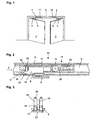
- Fig. 1 is a two-leaf door with a moving leaf 1 and a passive leaf 2 can be seen, with one above the door 1, 2 in or on the door frame arranged slide 9, in which the arranged on the slide arms 5, 6 of the door drives 3, 4 slides 7, 8 are guided. Furthermore, a release device 10 and a locking device 11 are arranged within the slide rail 9 for closing sequence control, which cooperate with the sliders 7, 8.
- the sliding arm 5 of the door drive 3 integrated in the moving leaf 1 executes a pivoting movement, which initially moves the slider 7 to the middle of the sliding rail and, in the event of further opening, in the direction of the door leaf strips.
- the triggering device 10 By opening the inactive leaf 2, the triggering device 10 via a transmission device 13, the locking device 11, not shown, whereby it blocks the open active leaf 1 in its direction of movement to the closed position.
- FIG. 2 shows a section of the slide rail 9 with the triggering device 10 arranged therein according to the invention in a sectional view.
- the triggering device 10 has a receptacle 12, in which the trigger slide 16, the latching element 19 and the clamping device 15 for the transmission element 13, for example a wire rope, are arranged.
- the transmission element 13 is fixed in the trigger slide 16, is guided over the guide roller 14 and cooperates with the locking device 11 for keeping the active leaf 1 open.
- the deflection roller 14 can be moved relative to the receptacle 12, whereby the transmission element 13 is tensioned.
- To the deflection roller 14 is fixed to a clamping element 22, which can be moved by a clamping screw 23 in the receptacle 12. It is advantageous that doubles the possible adjustment path for the transmission element 13 by the deflection of the transmission element 13 via the guide roller 14.
- the actuation of the locking device 11 is effected by a displacement movement of the trigger slide 16, which is spring-loaded, for example by a spring 11 arranged in the locking device 11 and the transmission element.
- the release slider 16 is fixed in its initial position, the closed position of the inactive leaf 2, guided by the locking element 19 guided in the receptacle 12, whereby the locking device 11 is in its release position, and whereby the active leaf is freely movable.
- this has one or more extensions 17, on each of which a holding element 18 is arranged.
- the holding element 18 may be a latching nose or a recess in the extension 17.
- the loaded in the direction of the extensions 17 by a spring 20 locking element 19 engages in the holding element 18, thereby preventing a sliding movement of the trigger slide 16.
- the slider 8 has a recessed area in which the extensions 17 and the latching element 19 project into and on which the triggering element 21 is arranged.
- the trip slider 16 can then move in the direction of the guide roller 14, which is blocked by the transmission member 13 and the locking device 11 of the active leaf.
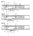
- FIGS. 4a to 4c is caused by the inactive leaf 2 sequence of movement of the slider 8 for actuating the locking device 11 is shown.
- the movement of the slider 8 and the trigger slider 16 can be seen from the line B, which is the same position in the FIGS. 4a to 4c features.
- the FIG. 4a shows the starting position in which the inactive leaf 2 is closed and the active leaf 1 can move freely. After opening the active leaf 1 the inactive leaf 2 can be opened, wherein the slider 8 first to the slide rail center, according to arrow C in FIG. 4b , emotional. In this case, the slider 8 arrives at its reversal point, wherein it is in contact with the release slide 16.
- the further opening of the passive leaf 2 now causes the direction reversal of the slider 8, according to arrow D in Fig. 4c , on the hinge side of the inactive leaf 2, whereby the locking element 19 runs onto the trigger element 21 and is lifted against the spring 20, and whereby the latching element 19 is disengaged from the retaining elements 18.
- the trip slider 16 can jump in the direction of the guide roller 14 move toward, with the transmission element 13 shifts and the locking device 11 is actuated to block the active leaf 1.
- An even further opening of the passive leaf 2 causes the slider 8 away from the trigger slide 16 after its maximum displacement movement, which may be determined by the bias of the transmission element 13 in the locking device 11, or even when the trigger slide within the receptacle 12 in a Stop position arrives. Due to the sudden displacement movement of the trigger slide 16 is a precise position for the onset of the effect of the locking device 11 in terms of the door opening angle possible.
- the design allows easy adjustment of the triggering device 10 by the receptacle 12, which can be fixed for example by clamping screws in the slide rail 9, is released, after which the inactive leaf is opened and the slider 8 through the release slider 16, the receptacle 12 in the position according to Fig. 4b shifts. Thereafter, the receptacle 12 is fixed in the slide rail 9 again, and the triggering device 10 is positioned.
Claims (14)
- Dispositif coordonnateur de fermeture de portes pivotantes à deux vantaux, comprenant un vantail semi-fixe (2) et un vantail mobile (1), qui sont pourvus d'entraînements de porte (3, 4), au moins l'entraînement de porte (4) du côté du vantail semi-fixe venant en prise par le biais d'un bras coulissant (6) et d'un coulisseau (8) dans un rail de glissement (9), et comprenant en outre un dispositif de déclenchement (10) pouvant être activé par le vantail semi-fixe (2) et un élément de transfert (13) qui est en liaison avec un dispositif de blocage (11) du dispositif coordonnateur de fermeture coopérant avec l'entraînement de porte (3) du vantail mobile (1), caractérisé en ce
qu'au début d'un mouvement d'ouverture du vantail semi-fixe (2), le coulisseau (8) du côté du vantail semi-fixe se déplace d'abord vers le centre du rail de glissement, le coulisseau (8) du côté du vantail semi-fixe présentant une région renfoncée, dans laquelle pénètrent un tiroir de déclenchement (16) sollicité par ressort par le dispositif de blocage (11) et disposé dans le dispositif de déclenchement (10) et un élément d'encliquetage sollicité par ressort (19) du dispositif de déclenchement, le tiroir de déclenchement (16) étant mise en prise par un élément de retenue (18) avec l'élément d'encliquetage (19) sollicité par ressort, de sorte que le tiroir de déclenchement (16) soit fixé et que le dispositif de blocage (11) soit dans sa position de libération, dans laquelle le vantail mobile (1) est librement mobile,
et en ce que le coulisseau (8), lors d'une ouverture poursuivie du vantail semi-fixe (2) dans son déplacement dans la direction des charnières de porte, déclenche l'élément d'encliquetage (19) pour l'actionnement du dispositif de blocage (11) afin de fixer le vantail mobile (1), et libère par saut le tiroir de déclenchement (16), par le fait qu'un élément de déclenchement (21) sur le coulisseau (8) du côté du vantail semi-fixe déplace l'élément d'encliquetage (19) contre un ressort (20) et l'élément d'encliquetage (19) parvient hors d'engagement avec l'élément de retenue (18) du tiroir de déclenchement (16). - Dispositif selon la revendication 1,
caractérisé en ce que l'élément d'encliquetage (19) est réalisé sous forme de tiroir qui est déplacé par le coulisseau (8). - Dispositif selon la revendication 1,
caractérisé en ce qu'au moins une saillie (17) est réalisée sur le tiroir de déclenchement (16), laquelle coopère avec l'élément d'encliquetage (19). - Dispositif selon la revendication 3,
caractérisé en ce que les éléments de retenue (18) sont réalisés sur une saillie (17) du tiroir de déclenchement (16). - Dispositif selon la revendication 1, caractérisé en ce que l'élément d'encliquetage (19) est sollicité par un élément élastique (20) dans la direction de sa position verrouillant le tiroir de déclenchement (16).
- Dispositif selon la revendication 1, caractérisé en ce que le coulisseau (8) présente un élément de déclenchement (21) qui actionne l'élément d'encliquetage (19) pour libérer le tiroir de déclenchement (16).
- Dispositif selon la revendication 1, caractérisé en ce que le tiroir de déclenchement (16) est en liaison fonctionnelle avec le dispositif de blocage (11) par le biais d'un élément de transfert (13).
- Dispositif selon la revendication 7, caractérisé en ce que l'élément de transfert (13) est un élément flexible et peut être dévié dans sa direction d'action.
- Dispositif selon la revendication 8, caractérisé en ce que l'élément flexible est dévié de 180° dans la direction d'action opposée.
- Dispositif selon la revendication 8, caractérisé en ce que la déviation de l'élément de transfert (13) a lieu par le biais d'une poulie de renvoi (14).
- Dispositif selon la revendication 10, caractérisé en ce que le dispositif de déclenchement (10) présente un dispositif de tensionnement (15) avec un élément de tensionnement (22) sur lequel est disposée la poulie de renvoi (14).
- Dispositif selon la revendication 11,
caractérisé en ce que l'élément de tensionnement (22) est guidé avec la poulie de renvoi (14) de manière déplaçable dans le logement (12). - Dispositif selon la revendication 12,
caractérisé en ce que la tension de l'élément de transfert (13) peut être ajustée par le déplacement de la poulie de renvoi (14). - Dispositif selon la revendication 13,
caractérisé en ce que le dispositif de tensionnement (15) présente une vis de tensionnement (22) pour ajuster la tension de l'élément de transfert (13).
Applications Claiming Priority (2)
| Application Number | Priority Date | Filing Date | Title |
|---|---|---|---|
| DE10360039A DE10360039B4 (de) | 2003-12-18 | 2003-12-18 | Vorrichtung zur Schließfolgeregelung für zweiflügelige Drehtüren |
| DE10360039 | 2003-12-18 |
Publications (4)
| Publication Number | Publication Date |
|---|---|
| EP1544395A2 EP1544395A2 (fr) | 2005-06-22 |
| EP1544395A3 EP1544395A3 (fr) | 2009-04-22 |
| EP1544395B1 true EP1544395B1 (fr) | 2011-11-02 |
| EP1544395B8 EP1544395B8 (fr) | 2012-03-21 |
Family
ID=34485537
Family Applications (1)
| Application Number | Title | Priority Date | Filing Date |
|---|---|---|---|
| EP04028652A Active EP1544395B8 (fr) | 2003-12-18 | 2004-12-03 | Dispositif coordonnateur de fermeture pour portes à deux vantaux |
Country Status (4)
| Country | Link |
|---|---|
| EP (1) | EP1544395B8 (fr) |
| AT (1) | ATE531886T1 (fr) |
| DE (1) | DE10360039B4 (fr) |
| ES (1) | ES2374519T3 (fr) |
Families Citing this family (2)
| Publication number | Priority date | Publication date | Assignee | Title |
|---|---|---|---|---|
| EP1801336A1 (fr) * | 2005-12-22 | 2007-06-27 | GEZE GmbH | Dispositif coordinateur de fermeture |
| AT515398A1 (de) * | 2014-01-29 | 2015-08-15 | Walter Ing Degelsegger | Vorrichtung für das Steuern der Schließfolge von zweiflügeligen Schwenktüren |
Family Cites Families (7)
| Publication number | Priority date | Publication date | Assignee | Title |
|---|---|---|---|---|
| DE8810389U1 (fr) * | 1988-08-17 | 1988-09-29 | Gretsch-Unitas Gmbh Baubeschlaege, 7257 Ditzingen, De | |
| DE29501776U1 (de) | 1995-02-07 | 1995-04-13 | Dorma Gmbh & Co Kg | Schließfolgeregler für eine zweiflügelige Tür |
| DE19605744A1 (de) * | 1995-09-07 | 1997-03-13 | Geze Gmbh & Co | Vorrichtung zur Schließfolge und/oder Öffnungsfolgeregelung für eine zweiflügelige Tür |
| DE19545402A1 (de) * | 1995-12-06 | 1997-06-12 | Geze Gmbh & Co | Schließfolgesteuerung für eine automatisch schließende, zweiflügelige Tür |
| DE19545401A1 (de) * | 1995-12-06 | 1997-06-12 | Geze Gmbh & Co | Schließfolgesteuerung für eine zweiflügelige Tür |
| DE19855425B4 (de) * | 1998-12-02 | 2014-02-06 | Ernst Schulte | Schließfolgeregelvorrichtung für eine zweiflügelige Tür |
| FI107634B (fi) * | 2000-02-18 | 2001-09-14 | Abloy Oy | Ovensulkemisjärjestely pariovia varten |
-
2003
- 2003-12-18 DE DE10360039A patent/DE10360039B4/de not_active Expired - Lifetime
-
2004
- 2004-12-03 EP EP04028652A patent/EP1544395B8/fr active Active
- 2004-12-03 AT AT04028652T patent/ATE531886T1/de active
- 2004-12-03 ES ES04028652T patent/ES2374519T3/es active Active
Also Published As
| Publication number | Publication date |
|---|---|
| EP1544395A2 (fr) | 2005-06-22 |
| DE10360039A1 (de) | 2005-07-28 |
| EP1544395A3 (fr) | 2009-04-22 |
| EP1544395B8 (fr) | 2012-03-21 |
| ES2374519T3 (es) | 2012-02-17 |
| ATE531886T1 (de) | 2011-11-15 |
| DE10360039B4 (de) | 2009-06-18 |
Similar Documents
| Publication | Publication Date | Title |
|---|---|---|
| EP0726379B1 (fr) | Une porte à double battants dont la fermeture est assurée l'une après l'autre | |
| EP0141902B1 (fr) | Dispositif de commande de la séquence de fermeture de portes à deux battants | |
| DE2920581C2 (de) | Zusatzverriegelung, insbesondere Mittelverriegelung, für Fenster, Türen od.dgl. | |
| EP1500766A2 (fr) | Appareil de levage de volet ou porte pliante à deux battants | |
| DE60111286T2 (de) | Türschliessungsanordnung für Doppeltüren | |
| EP1544394B1 (fr) | Dispositif pour immobiliser un vantail, particulièrement d'une porte ou fenêtre | |
| EP0324075B1 (fr) | Dispositif de commande de la séquence de fermeture de portes à deux battants | |
| EP0452710B1 (fr) | Dispositif de commande de séquence de fermeture des portes à double battants | |
| EP1544395B1 (fr) | Dispositif coordonnateur de fermeture pour portes à deux vantaux | |
| EP1544398B1 (fr) | Dispositif coordonnateur de fermeture pour portes à deux vantaux | |
| EP1612358B1 (fr) | Coordinateur de fermeture de portes à double battants | |
| DE102009031490A1 (de) | Schließfolgeregelung | |
| EP1096088B1 (fr) | Contrôle de fermeture ä séquence avec dispositif de verrouillage commandé par un battant stationnaire | |
| DE202004004341U1 (de) | Band für eine verdeckte Anordnung zwischen Zarge und Flügel | |
| EP1147278B1 (fr) | Dispositif de fermeture pour battants a croisement de fenetres, de portes ou similaires, sans montants, a deux battants | |
| DE10111732A1 (de) | Schliessfolgeregler für eine zweiflügelige Tür | |
| DE3609565C2 (de) | Schließfolgeregelvorrichtung für eine zweiflügelige Tür | |
| EP0985794A2 (fr) | Commande pour l'ouvrant d'une porte , d'une fenêtre ou similaire | |
| EP1544396B1 (fr) | Coordinateur de fermeture de portes à double battants | |
| DE102012220079B3 (de) | Schließfolgeregelung | |
| EP1544397A2 (fr) | Dispositif d'arrêt d'une aile de porte ou de fenêtre | |
| DE149998C (fr) | ||
| DE19520231A1 (de) | Torantrieb für ein Garagentor | |
| DE10107884B4 (de) | Schließfolgeregler | |
| EP2090730B1 (fr) | Dispositif de verrouillage |
Legal Events
| Date | Code | Title | Description |
|---|---|---|---|
| PUAI | Public reference made under article 153(3) epc to a published international application that has entered the european phase |
Free format text: ORIGINAL CODE: 0009012 |
|
| AK | Designated contracting states |
Kind code of ref document: A2 Designated state(s): AT BE BG CH CY CZ DE DK EE ES FI FR GB GR HU IE IS IT LI LT LU MC NL PL PT RO SE SI SK TR |
|
| AX | Request for extension of the european patent |
Extension state: AL BA HR LV MK YU |
|
| PUAL | Search report despatched |
Free format text: ORIGINAL CODE: 0009013 |
|
| AK | Designated contracting states |
Kind code of ref document: A3 Designated state(s): AT BE BG CH CY CZ DE DK EE ES FI FR GB GR HU IE IS IT LI LT LU MC NL PL PT RO SE SI SK TR |
|
| AX | Request for extension of the european patent |
Extension state: AL BA HR LV MK YU |
|
| 17P | Request for examination filed |
Effective date: 20090924 |
|
| 17Q | First examination report despatched |
Effective date: 20091105 |
|
| AKX | Designation fees paid |
Designated state(s): AT BE BG CH CY CZ DE DK EE ES FI FR GB GR HU IE IS IT LI LT LU MC NL PL PT RO SE SI SK TR |
|
| GRAP | Despatch of communication of intention to grant a patent |
Free format text: ORIGINAL CODE: EPIDOSNIGR1 |
|
| GRAS | Grant fee paid |
Free format text: ORIGINAL CODE: EPIDOSNIGR3 |
|
| GRAA | (expected) grant |
Free format text: ORIGINAL CODE: 0009210 |
|
| AK | Designated contracting states |
Kind code of ref document: B1 Designated state(s): AT BE BG CH CY CZ DE DK EE ES FI FR GB GR HU IE IS IT LI LT LU MC NL PL PT RO SE SI SK TR |
|
| REG | Reference to a national code |
Ref country code: GB Ref legal event code: FG4D Free format text: NOT ENGLISH |
|
| REG | Reference to a national code |
Ref country code: CH Ref legal event code: EP |
|
| RBV | Designated contracting states (corrected) |
Designated state(s): AT BE BG CH CY CZ DK EE ES FI FR GB GR HU IE IS IT LI LT LU MC NL PL PT RO SE SI SK TR |
|
| REG | Reference to a national code |
Ref country code: IE Ref legal event code: FG4D |
|
| REG | Reference to a national code |
Ref country code: DE Ref legal event code: R096 Ref document number: 502004013022 Country of ref document: DE Effective date: 20120105 Ref country code: DE Ref legal event code: R108 Ref document number: 502004013022 Country of ref document: DE Effective date: 20111117 |
|
| REG | Reference to a national code |
Ref country code: ES Ref legal event code: FG2A Ref document number: 2374519 Country of ref document: ES Kind code of ref document: T3 Effective date: 20120217 |
|
| REG | Reference to a national code |
Ref country code: NL Ref legal event code: VDEP Effective date: 20111102 |
|
| LTIE | Lt: invalidation of european patent or patent extension |
Effective date: 20111102 |
|
| PG25 | Lapsed in a contracting state [announced via postgrant information from national office to epo] |
Ref country code: LT Free format text: LAPSE BECAUSE OF FAILURE TO SUBMIT A TRANSLATION OF THE DESCRIPTION OR TO PAY THE FEE WITHIN THE PRESCRIBED TIME-LIMIT Effective date: 20111102 Ref country code: IS Free format text: LAPSE BECAUSE OF FAILURE TO SUBMIT A TRANSLATION OF THE DESCRIPTION OR TO PAY THE FEE WITHIN THE PRESCRIBED TIME-LIMIT Effective date: 20120302 |
|
| PG25 | Lapsed in a contracting state [announced via postgrant information from national office to epo] |
Ref country code: PL Free format text: LAPSE BECAUSE OF FAILURE TO SUBMIT A TRANSLATION OF THE DESCRIPTION OR TO PAY THE FEE WITHIN THE PRESCRIBED TIME-LIMIT Effective date: 20111102 Ref country code: PT Free format text: LAPSE BECAUSE OF FAILURE TO SUBMIT A TRANSLATION OF THE DESCRIPTION OR TO PAY THE FEE WITHIN THE PRESCRIBED TIME-LIMIT Effective date: 20120302 Ref country code: NL Free format text: LAPSE BECAUSE OF FAILURE TO SUBMIT A TRANSLATION OF THE DESCRIPTION OR TO PAY THE FEE WITHIN THE PRESCRIBED TIME-LIMIT Effective date: 20111102 Ref country code: SI Free format text: LAPSE BECAUSE OF FAILURE TO SUBMIT A TRANSLATION OF THE DESCRIPTION OR TO PAY THE FEE WITHIN THE PRESCRIBED TIME-LIMIT Effective date: 20111102 Ref country code: GR Free format text: LAPSE BECAUSE OF FAILURE TO SUBMIT A TRANSLATION OF THE DESCRIPTION OR TO PAY THE FEE WITHIN THE PRESCRIBED TIME-LIMIT Effective date: 20120203 Ref country code: SE Free format text: LAPSE BECAUSE OF FAILURE TO SUBMIT A TRANSLATION OF THE DESCRIPTION OR TO PAY THE FEE WITHIN THE PRESCRIBED TIME-LIMIT Effective date: 20111102 |
|
| REG | Reference to a national code |
Ref country code: IE Ref legal event code: FD4D |
|
| PG25 | Lapsed in a contracting state [announced via postgrant information from national office to epo] |
Ref country code: CY Free format text: LAPSE BECAUSE OF FAILURE TO SUBMIT A TRANSLATION OF THE DESCRIPTION OR TO PAY THE FEE WITHIN THE PRESCRIBED TIME-LIMIT Effective date: 20111102 |
|
| BERE | Be: lapsed |
Owner name: GEZE G.M.B.H. Effective date: 20111231 |
|
| PG25 | Lapsed in a contracting state [announced via postgrant information from national office to epo] |
Ref country code: SK Free format text: LAPSE BECAUSE OF FAILURE TO SUBMIT A TRANSLATION OF THE DESCRIPTION OR TO PAY THE FEE WITHIN THE PRESCRIBED TIME-LIMIT Effective date: 20111102 Ref country code: CZ Free format text: LAPSE BECAUSE OF FAILURE TO SUBMIT A TRANSLATION OF THE DESCRIPTION OR TO PAY THE FEE WITHIN THE PRESCRIBED TIME-LIMIT Effective date: 20111102 Ref country code: DK Free format text: LAPSE BECAUSE OF FAILURE TO SUBMIT A TRANSLATION OF THE DESCRIPTION OR TO PAY THE FEE WITHIN THE PRESCRIBED TIME-LIMIT Effective date: 20111102 Ref country code: IE Free format text: LAPSE BECAUSE OF FAILURE TO SUBMIT A TRANSLATION OF THE DESCRIPTION OR TO PAY THE FEE WITHIN THE PRESCRIBED TIME-LIMIT Effective date: 20111102 Ref country code: EE Free format text: LAPSE BECAUSE OF FAILURE TO SUBMIT A TRANSLATION OF THE DESCRIPTION OR TO PAY THE FEE WITHIN THE PRESCRIBED TIME-LIMIT Effective date: 20111102 Ref country code: MC Free format text: LAPSE BECAUSE OF NON-PAYMENT OF DUE FEES Effective date: 20111231 Ref country code: BG Free format text: LAPSE BECAUSE OF FAILURE TO SUBMIT A TRANSLATION OF THE DESCRIPTION OR TO PAY THE FEE WITHIN THE PRESCRIBED TIME-LIMIT Effective date: 20120202 |
|
| PG25 | Lapsed in a contracting state [announced via postgrant information from national office to epo] |
Ref country code: RO Free format text: LAPSE BECAUSE OF FAILURE TO SUBMIT A TRANSLATION OF THE DESCRIPTION OR TO PAY THE FEE WITHIN THE PRESCRIBED TIME-LIMIT Effective date: 20111102 |
|
| PLBE | No opposition filed within time limit |
Free format text: ORIGINAL CODE: 0009261 |
|
| REG | Reference to a national code |
Ref country code: FR Ref legal event code: ST Effective date: 20120831 |
|
| STAA | Information on the status of an ep patent application or granted ep patent |
Free format text: STATUS: NO OPPOSITION FILED WITHIN TIME LIMIT |
|
| 26N | No opposition filed |
Effective date: 20120803 |
|
| PG25 | Lapsed in a contracting state [announced via postgrant information from national office to epo] |
Ref country code: BE Free format text: LAPSE BECAUSE OF NON-PAYMENT OF DUE FEES Effective date: 20111231 |
|
| PG25 | Lapsed in a contracting state [announced via postgrant information from national office to epo] |
Ref country code: FR Free format text: LAPSE BECAUSE OF NON-PAYMENT OF DUE FEES Effective date: 20120102 |
|
| PG25 | Lapsed in a contracting state [announced via postgrant information from national office to epo] |
Ref country code: LU Free format text: LAPSE BECAUSE OF NON-PAYMENT OF DUE FEES Effective date: 20111203 |
|
| PG25 | Lapsed in a contracting state [announced via postgrant information from national office to epo] |
Ref country code: TR Free format text: LAPSE BECAUSE OF FAILURE TO SUBMIT A TRANSLATION OF THE DESCRIPTION OR TO PAY THE FEE WITHIN THE PRESCRIBED TIME-LIMIT Effective date: 20111102 |
|
| PG25 | Lapsed in a contracting state [announced via postgrant information from national office to epo] |
Ref country code: HU Free format text: LAPSE BECAUSE OF FAILURE TO SUBMIT A TRANSLATION OF THE DESCRIPTION OR TO PAY THE FEE WITHIN THE PRESCRIBED TIME-LIMIT Effective date: 20111102 |
|
| REG | Reference to a national code |
Ref country code: DE Ref legal event code: R107 Ref document number: 502004013022 Country of ref document: DE |
|
| PGFP | Annual fee paid to national office [announced via postgrant information from national office to epo] |
Ref country code: GB Payment date: 20221222 Year of fee payment: 19 Ref country code: FI Payment date: 20221222 Year of fee payment: 19 Ref country code: AT Payment date: 20221222 Year of fee payment: 19 |
|
| PGFP | Annual fee paid to national office [announced via postgrant information from national office to epo] |
Ref country code: ES Payment date: 20230224 Year of fee payment: 19 Ref country code: CH Payment date: 20221213 Year of fee payment: 19 |
|
| PGFP | Annual fee paid to national office [announced via postgrant information from national office to epo] |
Ref country code: IT Payment date: 20221228 Year of fee payment: 19 |