EP1544364A1 - Verkleidung für ein Vorwandinstallationssystem - Google Patents
Verkleidung für ein Vorwandinstallationssystem Download PDFInfo
- Publication number
- EP1544364A1 EP1544364A1 EP04030044A EP04030044A EP1544364A1 EP 1544364 A1 EP1544364 A1 EP 1544364A1 EP 04030044 A EP04030044 A EP 04030044A EP 04030044 A EP04030044 A EP 04030044A EP 1544364 A1 EP1544364 A1 EP 1544364A1
- Authority
- EP
- European Patent Office
- Prior art keywords
- component
- diaphragm plate
- support system
- cladding
- cladding according
- Prior art date
- Legal status (The legal status is an assumption and is not a legal conclusion. Google has not performed a legal analysis and makes no representation as to the accuracy of the status listed.)
- Withdrawn
Links
- 238000009434 installation Methods 0.000 claims abstract description 18
- 238000005253 cladding Methods 0.000 claims description 12
- 239000000853 adhesive Substances 0.000 claims description 4
- 230000001070 adhesive effect Effects 0.000 claims description 4
- 229910001220 stainless steel Inorganic materials 0.000 claims description 4
- 239000010935 stainless steel Substances 0.000 claims description 4
- 238000009428 plumbing Methods 0.000 abstract 2
- 238000011161 development Methods 0.000 description 3
- 230000018109 developmental process Effects 0.000 description 3
- 238000004519 manufacturing process Methods 0.000 description 3
- 230000008439 repair process Effects 0.000 description 3
- 239000000463 material Substances 0.000 description 2
- 230000006978 adaptation Effects 0.000 description 1
- 238000004873 anchoring Methods 0.000 description 1
- 238000013459 approach Methods 0.000 description 1
- 238000006243 chemical reaction Methods 0.000 description 1
- 238000010276 construction Methods 0.000 description 1
- 230000001934 delay Effects 0.000 description 1
- 230000001419 dependent effect Effects 0.000 description 1
- 238000013461 design Methods 0.000 description 1
- 239000010438 granite Substances 0.000 description 1
- 238000010438 heat treatment Methods 0.000 description 1
- 238000000034 method Methods 0.000 description 1
- 239000000203 mixture Substances 0.000 description 1
- 238000012986 modification Methods 0.000 description 1
- 230000004048 modification Effects 0.000 description 1
- 238000009418 renovation Methods 0.000 description 1
- 238000004381 surface treatment Methods 0.000 description 1
- 238000009423 ventilation Methods 0.000 description 1
- 239000002351 wastewater Substances 0.000 description 1
Images


Classifications
-
- E—FIXED CONSTRUCTIONS
- E04—BUILDING
- E04C—STRUCTURAL ELEMENTS; BUILDING MATERIALS
- E04C2/00—Building elements of relatively thin form for the construction of parts of buildings, e.g. sheet materials, slabs, or panels
- E04C2/02—Building elements of relatively thin form for the construction of parts of buildings, e.g. sheet materials, slabs, or panels characterised by specified materials
- E04C2/04—Building elements of relatively thin form for the construction of parts of buildings, e.g. sheet materials, slabs, or panels characterised by specified materials of concrete or other stone-like material; of asbestos cement; of cement and other mineral fibres
- E04C2/043—Building elements of relatively thin form for the construction of parts of buildings, e.g. sheet materials, slabs, or panels characterised by specified materials of concrete or other stone-like material; of asbestos cement; of cement and other mineral fibres of plaster
-
- E—FIXED CONSTRUCTIONS
- E03—WATER SUPPLY; SEWERAGE
- E03D—WATER-CLOSETS OR URINALS WITH FLUSHING DEVICES; FLUSHING VALVES THEREFOR
- E03D11/00—Other component parts of water-closets, e.g. noise-reducing means in the flushing system, flushing pipes mounted in the bowl, seals for the bowl outlet, devices preventing overflow of the bowl contents; devices forming a water seal in the bowl after flushing, devices eliminating obstructions in the bowl outlet or preventing backflow of water and excrements from the waterpipe
- E03D11/13—Parts or details of bowls; Special adaptations of pipe joints or couplings for use with bowls, e.g. provisions in bowl construction preventing backflow of waste-water from the bowl in the flushing pipe or cistern, provisions for a secondary flushing, for noise-reducing
- E03D11/14—Means for connecting the bowl to the wall, e.g. to a wall outlet
- E03D11/143—Mounting frames for toilets and urinals
- E03D11/146—Mounting frames for toilets and urinals with incorporated cistern
-
- E—FIXED CONSTRUCTIONS
- E04—BUILDING
- E04C—STRUCTURAL ELEMENTS; BUILDING MATERIALS
- E04C2/00—Building elements of relatively thin form for the construction of parts of buildings, e.g. sheet materials, slabs, or panels
- E04C2/44—Building elements of relatively thin form for the construction of parts of buildings, e.g. sheet materials, slabs, or panels characterised by the purpose
- E04C2/52—Building elements of relatively thin form for the construction of parts of buildings, e.g. sheet materials, slabs, or panels characterised by the purpose with special adaptations for auxiliary purposes, e.g. serving for locating conduits
- E04C2/521—Building elements of relatively thin form for the construction of parts of buildings, e.g. sheet materials, slabs, or panels characterised by the purpose with special adaptations for auxiliary purposes, e.g. serving for locating conduits serving for locating conduits; for ventilating, heating or cooling
-
- E—FIXED CONSTRUCTIONS
- E04—BUILDING
- E04F—FINISHING WORK ON BUILDINGS, e.g. STAIRS, FLOORS
- E04F17/00—Vertical ducts; Channels, e.g. for drainage
- E04F17/08—Vertical ducts; Channels, e.g. for drainage for receiving utility lines, e.g. cables, pipes
-
- E—FIXED CONSTRUCTIONS
- E04—BUILDING
- E04F—FINISHING WORK ON BUILDINGS, e.g. STAIRS, FLOORS
- E04F13/00—Coverings or linings, e.g. for walls or ceilings
Definitions
- the invention relates to a cladding for a wall installation system, especially for the sanitary sector, at the one in front of a wall mountable support system inlets and outlets and fasteners for sanitary objects to be attached receives.
- prewall installation systems In known prewall installation systems is a support system provided, which is placed in front of a wall. In the support system are inlets and outlets and fasteners for later to be attached sanitary objects available. Usually is the support system after its installation with Masonry or plasterboard clad and then tiled.
- the inventive design results in a Simplification in the production of the entire wall installation system. So can the prefabricated panel in be installed as soon as possible, since they are already as prefabricated is present and attached only to the support system must become. Also, it is no longer necessary breakthroughs for the inlets and outlets as well as for the fastening elements to create on site, since this already at the Production of the panel are introduced. This increases in addition, the precision in the production of the openings. Since the entire wall installation system of a can be attached to a single craftsman is not Coordination between craftsmen of different trades more required. Overall, therefore, can be with the Cladding according to the invention to a considerable extent time and To cut costs. Also in connection with possible repairs results from the panel according to the invention a considerable relief. Because the panel according to the invention Can be easily and quickly removed during a repair without damaging it as before the tiles are coming. Also, the panel according to the invention immediately re-assembled after completion of the repair be without a tiler is needed.
- the component from a plasterboard is easy to handle and edit and above low, so that the panel without great effort can be made.
- the component is a mounting plate attachable.
- This panel can z. B. from a plastic plate, a granite plate, a Korean plate o. The like. Of any material thickness consist.
- Such a cover plate is also unnecessary another Surface treatment of the component, which in turn costs and saves time.
- the diaphragm plate over Clamping profiles is held on the component.
- Such clamping profiles can z. B. circumferentially provided around the diaphragm plate be.
- the clamping profile can z. B. made of stainless steel, be bolted to the component and a the Have Blendplatte act on clamping leg.
- the diaphragm plate and / or the component can advantageously of profiles, preferably made of stainless steel, edged be, allowing an adaptation to individual desires Account can be taken.
- the panel over small adhesive surfaces with the Component to be connected.
- the lining according to the invention for a Pre-wall installation system in connection with a toilet can also be associated with any other sanitary facilities, eg. B. sink use Find.
- Fig. 1 is a panel for the wall installation system shown, consisting of a prefabricated component. 1 consists.
- the pretext installation system consists of a Supporting system 2, which is shown in section in Fig. 3.
- a cistern 3 for the toilet 4 In the support system 2 are in the illustrated embodiment a cistern 3 for the toilet 4, fasteners 5 for the toilet bowl and not shown and discharges for the toilet 4 housed.
- the device 1 may, for. B. consist of a plasterboard, which according to the dimensions of the support system 2 prefabricated and with the necessary openings 6 is provided. According to the illustrated embodiment are in the device 1 different sizes Passage openings 6 for the cistern 3 or its actuation, the fasteners 5 and the inlet and outlet lines appropriate. Depending on the type of arrangement of the support system 2 can also be on the side surfaces and / or the upper surface of the support system 2 panels are attached, the also prefabricated to the dimensions of the support system 2 are and if necessary with appropriate passages can be provided.
- the component 1 may be wholly or partially with a diaphragm plate Be provided 7, which also in their desired Size prefabricated and with corresponding openings is provided.
- the diaphragm plate 7 can be made as desired consist of any material.
- the diaphragm plate 7 is via clamping profiles 8, which via screws 9 are connected to the device 1, in their position held. In addition, the diaphragm plate 7 for securing the position connected to the device 1 via small adhesive surfaces be.
- the clamping profiles 8 have a directed to the diaphragm plate 7 Clamping tongue 10, with which they the diaphragm plate. 7 hold.
- clamping profiles 8 instead of anchoring the clamping profiles 8 only in the component, it is also possible, the clamping profiles 8 through the device 1 through in the support system 2 to fasten.
- the component 1 and / or the diaphragm plate 7 can be quite or partly of profiles, not shown, for. B. stainless steel be enclosed.
- the support system 2 is placed in front of a wall 11 and possibly attached to this. Then the prefabricated and provided with the corresponding passages 6 Component 1 fitted to the support system 2, that the fasteners 5 and the supply and discharge lines through the corresponding openings 6 extend.
- the toilet 4 is attached to the fasteners 5, connected to the inlets and outlets and via nuts 12 bolted to the fasteners 5.
- the component 1 and the diaphragm plate. 7 clamped between the support system 2 and the toilet 4 without it being special fasteners for the device 1 or the diaphragm plate 7 is required.
Landscapes
- Engineering & Computer Science (AREA)
- Architecture (AREA)
- Civil Engineering (AREA)
- Structural Engineering (AREA)
- Health & Medical Sciences (AREA)
- Life Sciences & Earth Sciences (AREA)
- Hydrology & Water Resources (AREA)
- Public Health (AREA)
- Water Supply & Treatment (AREA)
- Finishing Walls (AREA)
Abstract
Die Erfindung betrifft ein Vorwandinstallationssystem, insbesondere
für den Sanitärbereich, bei dem ein vor einer Wand
aufstellbares Tragsystem Zu- und Ableitungen sowie Befestigungselemente
für anzubringende Sanitärobjekte aufnimmt. Um
ein Vorwandinstallationssystem der eingangs genannten Art
derart weiterzubilden, dass der Aufwand verringert werden
kann, ist erfindungsgemäß vorgesehen, dass das Tragsystem
(2) mit einer vorgefertigten, den Abmessungen des Tragsystems
(2) entsprechenden Verkleidung (1) abdeckbar ist, welche
bereits vorgefertigte Durchtrittsöffnungen (6) für die
Zu- und Ableitungen sowie die Befestigungselemente (5) aufweist.
Description
Die Erfindung betrifft eine Verkleidung für ein Vorwandinstallationssystem,
insbesondere für den Sanitärbereich, bei
dem ein vor einer Wand aufstellbares Tragsystem Zu- und Ableitungen
sowie Befestigungselemente für anzubringende Sanitärobjekte
aufnimmt.
Solche Vorwandinstallationen sind hinlänglich bekannt. Sie
dienen z. B. bei Umbauten oder bei der Altbausanierung zu
einer schnellen und einfachen Installation von Sanitäreinrichtungen,
können aber auch im Zusammenhang mit Heizung,
Lüftung und/oder Abwasser Verwendung finden.
Bei bekannten Vorwandinstallationssystemen ist ein Tragsystem
vorgesehen, welches vor einer Wand aufgestellt wird. In
dem Tragsystem sind Zu- und Ableitungen und Befestigungselemente
für später anzubringende Sanitärobjekte vorhanden. Üblicherweise
wird das Tragsystem nach seiner Aufstellung mit
Mauerwerk oder Rigips verkleidet und anschließend verfliest.
Diese Vorgehensweise ist nicht nur zeitaufwendig, sondern
erfordert auch Handwerker verschiedener Gewerke: im vorgenannten
Fall z. B. zunächst Maurer, welche das Tragsystem
mit Mauerwerk verkleiden und anschließend Fliesenleger, welche
das Mauerwerk verfliesen. Gerade verschiedene Handwerker
sind oftmals aber nicht rechtzeitig und in der richtigen
Reihenfolge zur Stelle, so dass es zu Verzögerungen bei der
Bauausführung kommen kann.
Es ist daher Aufgabe der vorliegenden Erfindung, eine Verkleidung
für ein Vorwandinstallationssystem der eingangs genannten
Art derart weiterzubilden, dass der Aufwand verringert
werden kann.
Dies erfolgt bei einer Verkleidung für ein Vorwandinstallationssystem,
insbesondere für den Sanitärbereich, bei dem
ein vor einer Wand aufstellbares Tragsystem Zu- und Ableitungen
sowie Befestigungselemente für anzubringende Sanitärobjekte
aufnimmt, erfindungsgemäß dadurch, dass die Verkleidung
aus einem vorgefertigten, den Abmessungen des Tragsystems
entsprechenden Bauelement besteht, welches bereits vorgefertigte
Durchtrittsöffnungen für die Zu- und Ableitungen
sowie die Befestigungselemente aufweist.
Durch die erfindungsgemäße Ausgestaltung ergibt sich eine
Vereinfachung bei der Herstellung des gesamten Vorwandinstallationssystems.
So kann die vorgefertigte Verkleidung in
kürzester Zeit angebracht werden, da sie bereits als Fertigbauteil
vorhanden ist und nur an dem Tragsystem angebracht
werden muss. Auch ist es nicht mehr erforderlich, Durchbrechungen
für die Zu- und Ableitungen sowie für die Befestigungselemente
vor Ort zu erstellen, da diese bereits bei der
Herstellung der Verkleidung eingebracht werden. Dies erhöht
zusätzlich die Präzision bei der Herstellung der Durchbrechungen.
Da das gesamte Vorwandinstallationssystem von einem
einzigen Handwerker angebracht werden kann, ist auch keine
Abstimmung zwischen Handwerkern verschiedener Gewerke mehr
erforderlich. Insgesamt gesehen lassen sich somit mit der
erfindungsgemäßen Verkleidung in erheblichem Maße Zeit und
Kosten einsparen. Auch im Zusammenhang mit möglichen Reparaturen
ergibt sich durch die erfindungsgemäße Verkleidung eine
erhebliche Erleichterung. Denn die erfindungsgemäße Verkleidung
kann bei einer Reparatur leicht und schnell entfernt
werden, ohne dass es - wie bisher - zu einer Beschädigung
der Fliesen kommt. Auch kann die erfindungsgemäße Verkleidung
nach Beendigung der Reparatur sofort wieder montiert
werden, ohne dass ein Fliesenleger benötigt wird.
Vorteilhafte Weiterbildungen der erfindungsgemäßen Verkleidung
sind Gegenstand der Unteransprüche.
Gemäß einer vorteilhaften Weiterbildung besteht das Bauelement
aus einer Gipskartonplatte. Eine solche Gipskartonplatte
ist leicht zu handhaben und zu bearbeiten und darüber
hinaus günstig zu beziehen, so dass die Verkleidung ohne
großen Aufwand hergestellt werden kann.
Um den individuellen Wünschen des jeweiligen Nutzers gerecht
zu werden ist nach einer vorteilhaften Ausführungsform an
dem Bauelement eine Blendplatte anbringbar. Diese Blendplatte
kann z. B. aus einer Kunststoffplatte, einer Granitplatte,
einer Koreanplatte o. dgl. von beliebiger Materialdicke
bestehen. Eine solche Blendplatte erübrigt auch eine weitere
Oberflächenbearbeitung des Bauelementes, was wiederum Kosten
und Zeit spart.
Besonders einfach lässt sich die Blendplatte anbringen, wenn
nach einer bevorzugten Ausführungsform die Blendplatte über
Klemmprofile an dem Bauelement gehalten ist. Solche Klemmprofile
können z. B. umlaufend um die Blendplatte vorgesehen
sein. Wenn sich die Blendplatte z. B. am Boden abstützt,
kann auch eine Anordnung auf den beiden Längsseiten ausreichend
sein. Das Klemmprofil kann z. B. aus Edelstahl bestehen,
mit dem Bauelement verschraubt sein und einen die
Blendplatte beaufschlagenden Klemmschenkel aufweisen.
Die Blendplatte und/oder das Bauelement kann vorteilhafterweise
von Profilen, vorzugsweise aus Edelstahl, eingefasst
sein, so dass einer Anpassung an die individuellen Wünsche
Rechnung getragen werden kann.
Um die Befestigung des Bauelementes und ggf. der Blendplatte
weiter zu vereinfachen erfolgt nach einer bevorzugten Weiterbildung
die Befestigung des Bauelementes und ggf. der
Blendplatte automatisch mit der Montage der Sanitärobjekte.
Somit sind keine gesonderten Befestigungselemente für die
Verkleidung erforderlich. Beim Anbringen der Sanitärobjekte
wird vielmehr die Verkleidung und ggf. die Blendplatte durch
die Befestigungselemente für die Sanitärobjekte zwischen dem
Tragsystem und dem Sanitärobjekt festgeklemmt.
Um eine zusätzliche Lagesicherung der Blendplatte an dem
Bauelement zu erzielen, kann nach einer vorteilhaften Ausgestaltung
die Blendplatte über kleine Klebeflächen mit dem
Bauelement verbunden werden.
Weitere Einzelheiten, Merkmale und Vorteile der Erfindung
ergeben sich aus der nachfolgenden Beschreibung eines bevorzugten
Ausführungsbeispiels. Es zeigen:
- Fig. 1
- eine Vorderansicht der erfindungsgemäßen Verkleidung für eine Vorwandinstallationssystems,
- Fig. 2
- eine Seitenansicht der erfindungsgemäßen Verkleidung für eine Vorwandinstallationssystems,
- Fig. 3
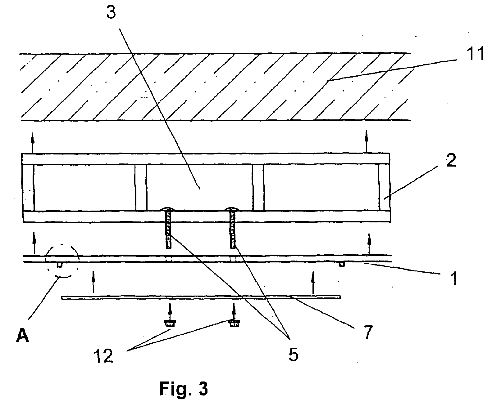
- einen Schnitt durch die erfindungsgemäße Verkleidung für eine Vorwandinstallationssystem entlang der Linie 3 - 3 in Fig. 1 in einer Explosionsansicht, und
- Fig. 4
- das Details "A" aus Fig. 3 in vergrößertem Maßstab.
In den Figuren ist die erfindungsgemäße Verkleidung für eine
Vorwandinstallationssystem im Zusammenhang mit einer Toilette
gezeigt, es kann aber auch im Zusammenhang mit beliebigen
anderen Sanitäreinrichtungen, z. B. Waschbecken Verwendung
finden.
In Fig. 1 ist eine Verkleidung für das Vorwandinstallationssystem
gezeigt, die aus einem vorgefertigten Bauelement 1
besteht. Das Vorwandinstallationssystem besteht aus einem
Tragsystem 2, welches im Schnitt in Fig. 3 dargestellt ist.
In dem Tragsystem 2 sind im dargestellten Ausführungsbeispiel
ein Spülkasten 3 für die Toilette 4, Befestigungselemente
5 für die Toilettenschüssel und nicht dargestellte Zu-
und Ableitungen für die Toilette 4 untergebracht.
Das Bauelement 1 kann z. B. aus einer Gipskartonplatte bestehen,
welche entsprechend den Abmessungen des Tragsystems
2 vorgefertigt und mit den erforderlichen Durchtrittsöffnungen
6 versehen ist. Entsprechend dem dargestellten Ausführungsbeispiel
sind in dem Bauelement 1 verschieden große
Durchtrittsöffnungen 6 für den Spülkasten 3 bzw. dessen Betätigung,
die Befestigungselemente 5 und die Zu- und Ableitungen
angebracht. Je nach Art der Anordnung des Tragsystems
2 können auch auf den Seitenflächen und/oder der oberen Fläche
des Tragsystems 2 Verkleidungen angebracht werden, die
ebenfalls auf die Abmessungen des Tragsystems 2 vorgefertigt
sind und bei Bedarf mit entsprechenden Durchtrittsöffnungen
versehen sein können.
Das Bauelement 1 kann ganz oder teilweise mit einer Blendplatte
7 versehen sein, die ebenfalls in ihrer gewünschten
Größe vorgefertigt und mit entsprechenden Durchtrittsöffnungen
versehen ist. Die Blendplatte 7 kann je nach Wunsch aus
beliebigem Material bestehen.
Die Blendplatte 7 ist über Klemmprofile 8, die über Schrauben
9 mit dem Bauelement 1 verbunden sind, in ihrer Position
gehalten. Zusätzlich kann die Blendplatte 7 zur Lagesicherung
über kleine Klebeflächen mit dem Bauelement 1 verbunden
sein. Die Klemmprofile 8 haben eine zur Blendplatte 7 gerichtete
Klemmzunge 10, mit welcher sie die Blendplatte 7
halten.
Statt die Klemmprofile 8 nur in dem Bauelement zu verankern,
ist es auch möglich, die Klemmprofile 8 durch das Bauelement
1 hindurch in dem Tragsystem 2 zu befestigen.
Das Bauelement 1 und/oder die Blendplatte 7 kann ganz oder
teilweise von nicht dargestellten Profilen, z. B. aus Edelstahl
eingefasst sein.
Die Montage der erfindungsgemäßen Verkleidung geht wie folgt
vor sich:
Zunächst wird das Tragsystem 2 vor einer Wand 11 aufgestellt
und ggf. an dieser befestigt. Dann wird die vorgefertigte
und mit den entsprechenden Durchtrittsöffnungen 6 versehene
Bauelement 1 passgenau so auf das Tragsystem 2 aufgesetzt,
dass sich die Befestigungselemente 5 und die Zu- und Ableitungen
durch die entsprechenden Durchtrittsöffnungen 6
erstrecken. Als nächstes wird die Blendplatte 7, die ggf.
vorher noch mit kleinen Klebeflächen versehen ist, zwischen
die Klemmprofile 8 derart eingesetzt, dass auch hier die Befestigungselemente
5 und die Zu- und Ableitungen durch entsprechende
Durchtrittsöffnungen hindurchragen. Zum Schluss
wird die Toilette 4 auf die Befestigungselemente 5 aufgesteckt,
mit den Zu- und Ableitungen verbunden und über Muttern
12 an den Befestigungselementen 5 verschraubt. Durch
diesen Befestigungsvorgang wird gewissermaßen automatisch
mit der Befestigung der Toilette 4 an dem Tragsystem 2
gleichzeitig auch das Bauelement 1 und die Blendplatte 7
zwischen dem Tragsystem 2 und der Toilette 4 festgeklemmt
ohne dass es spezieller Befestigungselemente für das Bauelement
1 oder die Blendplatte 7 bedarf.
Die vorhergehende Beschreibung der vorliegenden Erfindung
dient nur zu illustrativen Zwecken und nicht zum Zwecke der
Beschränkung der Erfindung. Im Rahmen der Erfindung sind
verschiedene Änderungen und Modifikationen möglich, ohne den
Umfang der Erfindung sowie ihrer Äquivalente zu verlassen.
- 1
- Bauelement
- 2
- Tragsystem
- 3
- Spülkasten
- 4
- Toilette
- 5
- Befestigungselement
- 6
- Durchtrittsöffnungen
- 7
- Blendplatte
- 8
- Klemmprofil
- 9
- Schrauben
- 10
- Klemmzunge
- 11
- Wand
- 12
- Mutter
Claims (7)
- Verkleidung für ein Vorwandinstallationssystem, insbesondere für den Sanitärbereich, bei dem ein vor einer Wand aufstellbares Tragsystem Zu- und Ableitungen sowie Befestigungselemente für anzubringende Sanitärobjekte aufnimmt, dadurch gekennzeichnet, dass die Verkleidung aus einem vorgefertigten, den Abmessungen des Tragsystems (2) entsprechenden Bauelement (1) besteht, welches bereits vorgefertigte Durchtrittsöffnungen (6) für die Zu- und Ableitungen sowie die Befestigungselemente (5) aufweist.
- Verkleidung nach Anspruch 1, dadurch gekennzeichnet, dass das Bauelement (1) aus einer Gipskartonplatte besteht.
- Verkleidung nach einem der vorhergehenden Ansprüche, dadurch gekennzeichnet, dass an dem Bauelement (1) eine Blendplatte (7) anbringbar ist.
- Verkleidung nach einem der vorhergehenden Ansprüche, dadurch gekennzeichnet, dass die Blendplatte (7) über Klemmprofile (8) an dem Bauelement (1) gehalten ist.
- Verkleidung nach einem der vorhergehenden Ansprüche, dadurch gekennzeichnet, dass die Blendplatte (7) und/oder das Bauelement (1) von Profilen, vorzugsweise aus Edelstahl eingefasst ist.
- Verkleidung nach einem der vorhergehenden Ansprüche, dadurch gekennzeichnet, dass die Befestigung des Bauelementes (1) und ggf. der Blendplatte (7) automatisch mit der Montage der Sanitärobjekte erfolgt.
- Verkleidung nach einem der vorhergehenden Ansprüche, dadurch gekennzeichnet, dass die Blendplatte (7) zur Lagesicherung über kleine Klebeflächen mit dem Bauelement (1) verbunden ist.
Applications Claiming Priority (2)
| Application Number | Priority Date | Filing Date | Title |
|---|---|---|---|
| DE20319636U DE20319636U1 (de) | 2003-12-17 | 2003-12-17 | Verkleidung für ein Vorwandinstallationssystem |
| DE20319636U | 2003-12-17 |
Publications (1)
| Publication Number | Publication Date |
|---|---|
| EP1544364A1 true EP1544364A1 (de) | 2005-06-22 |
Family
ID=32087654
Family Applications (1)
| Application Number | Title | Priority Date | Filing Date |
|---|---|---|---|
| EP04030044A Withdrawn EP1544364A1 (de) | 2003-12-17 | 2004-12-17 | Verkleidung für ein Vorwandinstallationssystem |
Country Status (2)
| Country | Link |
|---|---|
| EP (1) | EP1544364A1 (de) |
| DE (1) | DE20319636U1 (de) |
Cited By (1)
| Publication number | Priority date | Publication date | Assignee | Title |
|---|---|---|---|---|
| EP1916346A1 (de) | 2006-10-20 | 2008-04-30 | Geberit Technik Ag | Verkleidung für eine sanitäre Installationseinrichtung, Installationseinrichtung mit einer solchen Verkleidung und Verfahren zum Montieren einer Installationseinrichtung mit einer solchen Verkleidung |
Citations (5)
| Publication number | Priority date | Publication date | Assignee | Title |
|---|---|---|---|---|
| US2317428A (en) * | 1940-01-12 | 1943-04-27 | Wood Conversion Co | Wall tile clip |
| DE2222425A1 (de) * | 1972-05-04 | 1973-11-08 | Johns Manville | Befestigungs- und halteelement fuer an einer wand anzuordnende verkleidungsplatten |
| DE2556984A1 (de) * | 1975-12-18 | 1977-06-30 | Erwin Glock | Traggestell fuer ein wandhaengendes klosett und einen einbauspuelkasten |
| BE853239A (fr) * | 1977-04-05 | 1977-08-01 | Sabes John C | Clip pour la poste de lambris en lattes panneaux et dalles et ses procedes de pose |
| EP1001099A2 (de) * | 1998-11-09 | 2000-05-17 | DAL-Georg Rost & Söhne Sanitärarmaturen GmbH | Installationselement |
-
2003
- 2003-12-17 DE DE20319636U patent/DE20319636U1/de not_active Expired - Lifetime
-
2004
- 2004-12-17 EP EP04030044A patent/EP1544364A1/de not_active Withdrawn
Patent Citations (5)
| Publication number | Priority date | Publication date | Assignee | Title |
|---|---|---|---|---|
| US2317428A (en) * | 1940-01-12 | 1943-04-27 | Wood Conversion Co | Wall tile clip |
| DE2222425A1 (de) * | 1972-05-04 | 1973-11-08 | Johns Manville | Befestigungs- und halteelement fuer an einer wand anzuordnende verkleidungsplatten |
| DE2556984A1 (de) * | 1975-12-18 | 1977-06-30 | Erwin Glock | Traggestell fuer ein wandhaengendes klosett und einen einbauspuelkasten |
| BE853239A (fr) * | 1977-04-05 | 1977-08-01 | Sabes John C | Clip pour la poste de lambris en lattes panneaux et dalles et ses procedes de pose |
| EP1001099A2 (de) * | 1998-11-09 | 2000-05-17 | DAL-Georg Rost & Söhne Sanitärarmaturen GmbH | Installationselement |
Cited By (1)
| Publication number | Priority date | Publication date | Assignee | Title |
|---|---|---|---|---|
| EP1916346A1 (de) | 2006-10-20 | 2008-04-30 | Geberit Technik Ag | Verkleidung für eine sanitäre Installationseinrichtung, Installationseinrichtung mit einer solchen Verkleidung und Verfahren zum Montieren einer Installationseinrichtung mit einer solchen Verkleidung |
Also Published As
| Publication number | Publication date |
|---|---|
| DE20319636U1 (de) | 2004-04-01 |
Similar Documents
| Publication | Publication Date | Title |
|---|---|---|
| DE102009055934A1 (de) | Duschablaufsystem und Aufnahmeelement für ein Duschablaufsystem | |
| DE102009033038B4 (de) | Einbauleuchte | |
| DE4345049A1 (de) | Sanitärinstallationssystem | |
| EP4073324A1 (de) | Anordnung für die installation und montage eines waschbecken | |
| EP1747747A2 (de) | Verfahren zur Schaffung einer Einstiegsöffnung in bestehende Badewannen | |
| EP0731223B1 (de) | Montagevorrichtung zur tragenden Befestigung einer Sanitäreinrichtung | |
| EP3321430B1 (de) | Befestigung einer abdeckplatte einer revisionsöffnung | |
| EP2407603B1 (de) | Montageeinrichtung mit einem Montagegestell und Verfahren zum Montieren einer solchen Montageeinrichtung | |
| DE3517907A1 (de) | Wc-installationseinheit | |
| DE10210494C1 (de) | Tragvorrichtung für einen Sanitärkörper | |
| EP2690229B1 (de) | Montageeinrichtung für eine sanitäre Apparatur | |
| DE20319636U1 (de) | Verkleidung für ein Vorwandinstallationssystem | |
| EP1916346A1 (de) | Verkleidung für eine sanitäre Installationseinrichtung, Installationseinrichtung mit einer solchen Verkleidung und Verfahren zum Montieren einer Installationseinrichtung mit einer solchen Verkleidung | |
| EP1255896A1 (de) | Bausatz zur erzeugung insbesondere einer vorwand-eckinstallation für ein wc od. dgl. | |
| DE10207067A1 (de) | Bausatz zur Erzeugung insbesondere einer Vorwand-Eckinstallation für ein WC oder dgl. | |
| DE4433354C2 (de) | Sanitär-Vorwand | |
| DE102023003854B4 (de) | Universelle rahmenlose Montageplatte für die Sanierung und Nachrüstung von WC-Spüleinheiten mit Unterputzspülkasten | |
| DE202015001752U1 (de) | Spüleinheit | |
| EP1367187A2 (de) | Bausatz für einen wassergespülten Sanitärgegenstand | |
| DE19919612C1 (de) | Installationselement für sanitäre Objekte | |
| EP1245748A2 (de) | Tragvorrichtung für sanitäre Einrichtungen | |
| DE2457953A1 (de) | Montageblock fuer wandhaengende wc-becken, urinale o.dgl. | |
| DE29812802U1 (de) | Spritzschutz-Wandverkleidungsplatte für sanitäre Einrichtungen | |
| DE202023003098U1 (de) | Universelle rahmenlose Montageplatte für die Sanierung und Nachrüstung von WC-Spüleinheiten mit Unterputzspülkasten | |
| EP2995733A1 (de) | Wandablaufrinne für eine dusche |
Legal Events
| Date | Code | Title | Description |
|---|---|---|---|
| PUAI | Public reference made under article 153(3) epc to a published international application that has entered the european phase |
Free format text: ORIGINAL CODE: 0009012 |
|
| AK | Designated contracting states |
Kind code of ref document: A1 Designated state(s): AT BE BG CH CY CZ DE DK EE ES FI FR GB GR HU IE IS IT LI LT LU MC NL PL PT RO SE SI SK TR |
|
| AX | Request for extension of the european patent |
Extension state: AL BA HR LV MK YU |
|
| AKX | Designation fees paid | ||
| STAA | Information on the status of an ep patent application or granted ep patent |
Free format text: STATUS: THE APPLICATION IS DEEMED TO BE WITHDRAWN |
|
| 18D | Application deemed to be withdrawn |
Effective date: 20051223 |
|
| REG | Reference to a national code |
Ref country code: DE Ref legal event code: 8566 |