EP1544071B1 - Procédé et dispositif pour estimer l'intention d'un conducteur - Google Patents
Procédé et dispositif pour estimer l'intention d'un conducteur Download PDFInfo
- Publication number
- EP1544071B1 EP1544071B1 EP04029607A EP04029607A EP1544071B1 EP 1544071 B1 EP1544071 B1 EP 1544071B1 EP 04029607 A EP04029607 A EP 04029607A EP 04029607 A EP04029607 A EP 04029607A EP 1544071 B1 EP1544071 B1 EP 1544071B1
- Authority
- EP
- European Patent Office
- Prior art keywords
- intention
- driver
- imaginary
- time
- imaginary drivers
- Prior art date
- Legal status (The legal status is an assumption and is not a legal conclusion. Google has not performed a legal analysis and makes no representation as to the accuracy of the status listed.)
- Expired - Fee Related
Links
Images


Classifications
-
- B—PERFORMING OPERATIONS; TRANSPORTING
- B60—VEHICLES IN GENERAL
- B60W—CONJOINT CONTROL OF VEHICLE SUB-UNITS OF DIFFERENT TYPE OR DIFFERENT FUNCTION; CONTROL SYSTEMS SPECIALLY ADAPTED FOR HYBRID VEHICLES; ROAD VEHICLE DRIVE CONTROL SYSTEMS FOR PURPOSES NOT RELATED TO THE CONTROL OF A PARTICULAR SUB-UNIT
- B60W40/00—Estimation or calculation of non-directly measurable driving parameters for road vehicle drive control systems not related to the control of a particular sub unit, e.g. by using mathematical models
- B60W40/08—Estimation or calculation of non-directly measurable driving parameters for road vehicle drive control systems not related to the control of a particular sub unit, e.g. by using mathematical models related to drivers or passengers
- B60W40/09—Driving style or behaviour
-
- B—PERFORMING OPERATIONS; TRANSPORTING
- B60—VEHICLES IN GENERAL
- B60W—CONJOINT CONTROL OF VEHICLE SUB-UNITS OF DIFFERENT TYPE OR DIFFERENT FUNCTION; CONTROL SYSTEMS SPECIALLY ADAPTED FOR HYBRID VEHICLES; ROAD VEHICLE DRIVE CONTROL SYSTEMS FOR PURPOSES NOT RELATED TO THE CONTROL OF A PARTICULAR SUB-UNIT
- B60W50/00—Details of control systems for road vehicle drive control not related to the control of a particular sub-unit, e.g. process diagnostic or vehicle driver interfaces
- B60W50/08—Interaction between the driver and the control system
- B60W50/10—Interpretation of driver requests or demands
-
- B—PERFORMING OPERATIONS; TRANSPORTING
- B60—VEHICLES IN GENERAL
- B60T—VEHICLE BRAKE CONTROL SYSTEMS OR PARTS THEREOF; BRAKE CONTROL SYSTEMS OR PARTS THEREOF, IN GENERAL; ARRANGEMENT OF BRAKING ELEMENTS ON VEHICLES IN GENERAL; PORTABLE DEVICES FOR PREVENTING UNWANTED MOVEMENT OF VEHICLES; VEHICLE MODIFICATIONS TO FACILITATE COOLING OF BRAKES
- B60T2201/00—Particular use of vehicle brake systems; Special systems using also the brakes; Special software modules within the brake system controller
- B60T2201/08—Lane monitoring; Lane Keeping Systems
- B60T2201/086—Lane monitoring; Lane Keeping Systems using driver related features
Definitions
- This application generally relates to system and method for estimating an operator's intention and providing operation assistance, and more particularly, to a driver's intention estimation and driving assistance system.
- a number of methods and systems have been proposed for providing assistance in operating a device, system or machine, such as an automobile.
- driving assistance systems were disclosed in U.S. Published Patent Application No. 20030060936 A1 , published Mar. 27, 2003 and U.S. Published Patent Application No. 2004172185 A1, published Sep. 2, 2004 .
- a system for estimating a driver's intention may collect estimates of the driver's intention using movement of the driver's eyes. For example, directions to which the driver's eyes turn are projected onto a plane divided into a number of regions, for calculating a distribution of projected eye directions over the divided regions to estimate the driver's intention.
- such type of systems lacks accuracy in estimating the driver's intention because the driver's eyes move all the time and are not always related to a "driving" intention of the driver.
- US 2003/0167112 A1 discloses a vehicle agent system wherein a response from a driver is stored in a RAM, the selected response being determined to be the practice response in case the driver does not input any further command.
- This disclosure presents system, control process and method that provide effective estimation of an operator's intention in operating a device, system or machine.
- the advantages, operations and detailed structures of the disclosed methods and systems will be appreciated and understood from the descriptions provided herein.
- An exemplary system and method according to this disclosure estimate an operator's intention by utilizing data related to a plurality of reference operators, such as hypothetical or imaginary operators. Each of the imaginary operators has a behavior pattern, such as an associated operation and corresponding intention. A determination is made to identify an imaginary operator that has the closest behavior pattern to the real operator. An estimated intention of the real operator is generated based on information or attributes related to the identified imaginary operator, such as the associated intention of the identified imaginary operator.
- An exemplary system of this disclosure may be used to estimate an intention of a driver of a vehicle.
- the exemplary system includes a first device configured to detect an operation of a real driver of a vehicle, and a second device configured to calculate a respective likelihood value for each of a plurality of imaginary drivers based on the operation of the real driver and an operation of each of the plurality of imaginary drivers.
- the respective operation of each of the plurality of imaginary drivers is associated with an intention.
- the system further includes a third device configured to determine an estimated intention of the real driver based on the respective likelihood value of each of the plurality of imaginary drivers.
- the first, second and third devices may be implemented using microcontrollers and associated control codes and/or software.
- one of the imaginary drivers is selected based on the respective likelihood values of the drivers.
- the estimated intention of the driver is determined based on the intention of the selected one of the plurality of imaginary drivers.
- an operation of the real driver at each one of different points in time is detected.
- the respective likelihood value for each of the plurality of imaginary drivers is generated based on partial likelihood values of each of the plurality of imaginary drivers at the different points in time.
- Each of the partial likelihood values is respectively associated with a respective operation of one of the plurality of imaginary drivers at each one of the different points in time, and is generated based on the respective detected operation of the real driver at each one of the different points in time and the respective operation of one of the plurality of imaginary drivers at each one of the different points in time.
- each respective likelihood value for each of the plurality of imaginary drivers is a respective summation of partial likelihood values of each of the plurality of imaginary drivers at the different points in time.
- data related to at least one additional imaginary driver at a selected point in time is generated based on the intention of a first one of the plurality of imaginary drivers at a point of time preceding the selected point of time, wherein each of the at least one additional imaginary driver has an associated intention and operation at each respective one of the different points in time.
- the intention of each of the at least one additional imaginary driver at the selected point of time is different from the intention of the first one of the plurality of imaginary drivers at the selected point of time.
- each additional imaginary driver assumes the associated intention of the first one of the plurality of imaginary drivers at each point in time preceding the selected point in time.
- an intention corresponding to a new point in time is generated based on the respective intention of each of the imaginary drivers at a point in time preceding the new point in time.
- a selected one of the imaginary drivers is eliminated based on an intention of the selected one of the plurality of imaginary drivers at a specific point in time and an operation status of the vehicle.
- a risk potential related to the vehicle is calculated using various known approaches, such as by detecting distances between the vehicle and other vehicles, the speed of the vehicle, etc.
- the system includes a device for providing a signal, such as a haptic signal, to the operator or driver to indicate the status of the risk potential associated with the operation or the vehicle.
- a resistant force or a reaction force that a driver experiences when operating a device to control the vehicle, such as an accelerator pedal is varied or regulated based on the calculated risk potential.
- a response of the steering wheel or a reaction force to be experienced by a driver when turning the steering wheel is varied or adjusted based on the calculated risk potential.
- the risk potential is adjusted based on the estimated intention of the operator or driver, such that a more suitable haptic signal can be generated considering the intention of the operator.
- the haptic signal is generated based on the calculated risk potential and the estimated intention of the real driver.
- a driver's intention estimating system 1 for a vehicle includes a vehicle's environment detector 10, a vehicle's status detector 20, a real driver's operation detector 30, an imaginary driver's operation calculator 40, a likelihood value calculator 50, and a driver's intention estimator 60.
- the vehicle's environment detector 10 detects state of environment within a field around the vehicle.
- the vehicle's status detector 20 detects status of the vehicle.
- the real driver's operation detector 30 detects an operation of a real driver in driving the vehicle.
- the driver's intention estimating system 1 has access to reference data, such as data related to a plurality of imaginary drivers. Each of the plurality of imaginary drivers has an associated intention and a corresponding operation to operate the vehicle according to the respective intention.
- the driver's intention estimating system 1 evaluates how close the detected operation of the real driver to each of the plurality of imaginary drivers. For instance, system 1 calculates a likelihood value for each of the imaginary drivers by comparing the detected operation of the real driver to an associated operation of each imaginary driver.
- the driver's intention estimating system 1 estimates the intention of the real driver based on the determined likelihood values.
- the vehicle's environment detector 10 includes a front camera that covers a field of front view and a yaw angle sensor.
- the front camera acquires image on road conditions, for example, within the field of front view.
- the vehicle's environment detector 10 detects a lateral distance y of the vehicle from a centerline within a lane, and a yaw angle ⁇ of the vehicle with respect a line parallel to the centerline.
- the vehicle's environment detector 10 is equipped with an image processor that processes the acquired image.
- the vehicle's status detector 20 includes a vehicle speed sensor that detects a speed of the vehicle.
- the real driver's operation detector 30 includes a steering angle sensor that is provided in a steering system to detect a steering angle of the vehicle.
- the imaginary driver's operation calculator 40, likelihood value calculator 50, and driver's intention estimator 60 are implemented using one or more microcomputers or microcontrollers executing microcode, software programs and/or instructions.
- the microcode and/or software reside in volatile and/or non-volatile data storage devices and/or machine-readable data storage medium such as read only memory (ROM) devices, random access memory (RAM) devices, SRAM, PROM, EPROM, CD-ROM, disks, carrier waves, etc.
- the imaginary driver's operation calculator 40 calculates operation of each imaginary driver in driving the vehicle as directed by an intention associated with each imaginary driver.
- the likelihood value calculator 50 calculates a likelihood value based on the calculated operation of each imaginary driver and the detected operation of the real driver.
- the driver's intention estimator 60 estimates an intention of the real driver by comparing the calculated likelihood values with each other.
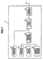
- FIG. 2 illustrates a driver's intention estimation processing program. Execution of this program is repeated at a regular interval of, for example, 50 milliseconds.
- the microcomputer reads in, as inputs, a lateral position y of the vehicle within a lane (or track) and a yaw angle ⁇ of the vehicle.
- the lateral position y is a distance of a center O of the vehicle from the centerline of the lane
- the yaw angle ⁇ is an angle through which the vehicle is turned relative to the centerline of the lane.
- the microcomputer calculates operation Oid of each of a plurality of imaginary drivers.
- three imaginary drivers are utilized, including an imaginary driver A having a lane-keeping intention (LK), an imaginary driver B having a lane-change intention to the right (LCR), and an imaginary driver C having a lane-change intention to the left (LCL).
- the microcomputer calculates operation Oid of each of these three imaginary drivers A, B and C in driving the vehicle as directed by the given intention. More particularly, the microcomputer calculates, as the operation Oid, a steering angle ⁇ id, by which each of the three imaginary drivers A, B and C manipulates a steering wheel in driving the vehicle as directed by the given intention.
- the following description discusses how the operation Oid is calculated.
- the microcomputer sets at least one reference point LK(i) in front on a longitudinal centerline of the vehicle at a distance px(i) from the center O of the vehicle, and calculates a lateral position p.lk(px(i)) of the reference point LK(i) from a centerline of a lane.
- At least one reference point LK(i) includes any desired number of reference points LK(i). In this example, as shown in Fig.
- two reference points LK(1) and LK(2) are set on the longitudinal centerline of the vehicle at different distances px(1) and px(2) from the center O of the vehicle.
- the distance px(i) may have varying values with different vehicle speeds.
- a lateral distance lat-pos(px(i)) of the reference point LK(i) from the centerline of the lane is dependent on, and thus determined by, the yaw angle ⁇ and the distance px(i), which may be, for example, given by processing the acquired image from the front camera.
- the microcomputer sets at least one reference point LCR(i). At least one reference point LCR(i) includes any desired number of reference points LCR(i). In this example, as shown in Fig. 3 , two reference points LCR(1) and LCR(2) are set.
- the microcomputer sets at least one reference point LCL(i). At least one reference point LCL(i) includes any desired number of reference points LCL(i). In this example, as shown in Fig. 3 , two reference points LCL(1) and LCL(2) are set.
- step S103 the microcomputer receives, as an input, an operation Ord of a real driver by reading in a current steering angle ⁇ rd detected by the real driver operation detector 30.
- the real driver's operation Ord is the detected real driver's steering angle ⁇ rd.
- the microcomputer calculates a likelihood value Pid based on the calculated operation Oid of each imaginary driver and the detected operation Ord of the real driver.
- the likelihood value Pid is used to mean any one of a likelihood value Pid.lk of the imaginary driver A, a likelihood value Pid.lcr of the imaginary driver B, and a likelihood value Pid.lcl of the imaginary driver C.
- the calculated operation Oid of each imaginary driver is expressed by any one of the calculated steering angles ⁇ id.lk, ⁇ id.lcr, and ⁇ id.lcl
- An imaginary driver's steering angle ⁇ id is used to mean any one of these calculated steering angles ⁇ id.lk, ⁇ id.lcr, and ⁇ id.lcl.
- the detected operation Ord of the real driver is expressed by the detected real driver's steering angle ⁇ rd.
- the likelihood value Pid of each imaginary driver is a logarithmic probability of a normalized value of the imaginary driver's steering angle ⁇ id against a normal distribution, where the mean (e) is the real driver's steering angle ⁇ rd and the variance ( ⁇ ) is a predetermined value ⁇ rd such as a standard deviation of steering angles.
- the value of ⁇ rd depends on characteristics of the vehicle, such as the steering gear ratio, and/or the speed of the vehicle ⁇ rd may range from -15 degrees to +15 degrees, such as between 3 to 5 degrees. Of course, other values of ⁇ rd may be used depending on the type and/or characteristics of vehicles.
- Pid log Probn ⁇ ⁇ id - ⁇ rd / prd
- Probn is a probability density function that is used to calculate a probability with which a given sample is observed from a population expressed by the normal distribution.
- the microcomputer calculates a likelihood value Pid.lk of lane-keeping (LK), a likelihood value Pid.lcr of lane change to the right (LCR), and a likelihood value Pid.lcl of lane change to the left (LCL). Then, the logic goes to step S105.
- LK lane-keeping
- LCR likelihood value Pid.lcr of lane change to the right
- LCL likelihood value Pid.lcl of lane change to the left
- the microcomputer estimates an intention ⁇ rd of the real driver.
- the microcomputer chooses that one of the imaginary driver's intentions that has the maximum value among the calculated likelihood values, Pid.lk, Pid.lcr and Pid.lcl, as the intention ⁇ rd of the real driver.
- the microcomputer provides, as an output, the estimated real driver's intention ⁇ rd.
- the reference numeral 2 designates a driver's intention estimating system.
- This system 2 is substantially the same as the above described system 1.
- Like reference numerals are used to designate like elements throughout Figs. 1 and 4 .
- the system 2 is different from the system 1 in that, instead of calculating a likelihood value Pid for each of imaginary drivers based on the present data, a likelihood value Pids for each of the imaginary drivers is calculated based on a series of present and past data obtained within a predetermined period of time for use in estimating a real driver's intention ⁇ rd.
- the system 2 is provided with a functional block 70 labeled "likelihood values Pids calculator” instead of the functional block 50 labeled "likelihood value Pid calculator” illustrated in Fig. 1 .
- the driver's intention estimating system 2 includes likelihood value Pids calculator 70.
- the likelihood values Pids calculator 70 may be implemented using one or more microcomputers or microcontrollers executing microcode, software programs and/or instructions. Similarly to an imaginary driver's operation calculator 40 and a driver's intention estimator 60, the likelihood value Pids calculator 70 may be implemented using software or instructions to be executed by a central processor unit (CPU)
- CPU central processor unit
- FIG. 5 illustrates a driver's intention estimation processing program. Execution of this program is repeated at a regular interval of, for example, 50 milliseconds.
- the flow chart illustrated in Fig. 5 has steps S201, S202, S203 and S204, which correspond to the steps S101, S102, S103 and S104 of the flow chart illustrated in Fig. 2 .
- the microcomputer performs substantially the same jobs down to step S204 where the microcomputer calculates instantaneous likelihood values Pid, which generally denote a likelihood value Pid.lk of lane-keeping (LK), a likelihood value Pid.lcr of lane change to the right (LCR), and a likelihood value Pid.lcl of lane change to the left (LCL).
- LK likelihood value Pid.lk of lane-keeping
- LCR likelihood value Pid.lcr of lane change to the right
- LCL likelihood value Pid.lcl of lane change to the left
- the calculated likelihood values Pid are not used immediately for arithmetic operation in estimating an intention ⁇ rd of a real driver, but they are stored as Pid(t) in one or more memory portions, each being capable of retaining a series of m, in number, stored data.
- three memory portions namely, first, second and third memory portions, are provided for the lane-keeping intention (LK), lane-change intention to the right (LCR) and lane-change intention to the left (LCL) possessed by three imaginary drivers A, B and C, respectively.
- the first memory portion for the lane-keeping intention (LK) possessed by the imaginary driver A stores a LK series of m, in number, current and past likelihood values for a present point in time indicated by (t) back to a past point in time indicated by (t -m + 1).
- the LK series of m likelihood values are stored at locations indicated at Pid.lk(t), Pid.lk(t -1) ...
- the second memory portion for the lane-change intention to the right (LCR) possessed by the imaginary driver B stores a LCR series of m current and past likelihood values ranging from a present point in time indicated by (t) back to a past point in time indicated by (t -m + 1).
- the LCR series of m likelihood values are stored at locations indicated at Pid.lcr(t), Pid.lcr(t -1) ... , and Pid.lcr(t -m + 1).
- the third memory portion for the lane-change intention to the left (LCL) possessed by the imaginary driver C stores a LCL series of m, in number, likelihood values for present and past points in time ranging from the present moment indicated by (t) back to a past point in time indicated by (t -m + 1).
- the LCL series of m likelihood values are stored at locations indicated at Pid.lcl(t), Pid.lcl(t -1) ... , and Pid.lcl(t -m + 1).
- the equation Eq. 9 states that the collective likelihood value Pids is the product of the respective likelihood values of the series Pid(t) ⁇ Pid(t -m + 1).
- the microcomputer calculates a LK collective likelihood value Pids.lk of the LK series, a LCR collective likelihood value Pids.lcr of the LCR series, and a LCL collective likelihood value Pids.lcl of the LCL series.
- the logic goes to step S 106.
- the microcomputer estimates an intention ⁇ rd of the real driver.
- the microcomputer chooses that one of the imaginary driver's intentions which has gained the maximum value among the calculated LK, LCR and LCL collective likelihood values Pids.lk, Pids.lcr and Pids.lcl for the intention ⁇ rd of the real driver.
- the microcomputer provides, as an output, the estimated real driver's intention ⁇ rd.
- a dynamic family of imaginary drivers is provided.
- the number and characteristics of the family members are dynamic over time and some of them are designed to behave as directed by an intention changing over time.
- the reference numeral 3 designates a driver's intention estimating system.
- This system 3 is substantially the same as system 2 illustrated previously in Fig. 4 .
- Like reference numerals are used to designate like elements throughout Figs. 4 and 7 .
- the system 3 is different from the system 2 in that, instead of using the less dynamic family of imaginary drivers A, B and C for calculating a collective likelihood value Pids for each imaginary driver, a dynamic family of imaginary drivers are used for calculating a collective likelihood value P(j)ids, where j is any integer, for each imaginary driver, to increase the accuracy in estimating a real driver's intention ⁇ rd.
- the driver's intention estimating system 3 is different from the system 2 in that a functional block 80 labeled "imaginary driver's intention generating section" is newly provided for supporting the dynamic family of imaginary drivers.
- the imaginary driver's intention generating section 80 may be implemented by using one or more microcomputers and/or software, microcode and/or instructions.
- the system 3 is different from the system 2 in that a functional block 90 labeled "likelihood value P(j)ids calculator” is provided instead of the likelihood value Pids calculator 70.
- the likelihood value P(j)ids calculator 90 may be implemented using one or more microcomputers and/or software, microcode and/or instructions.
- the likelihood value P(j)ids calculator 90 and the imaginary driver's intention generating section 80 may be implemented using software to be executed by a central processor unit (CPU).
- CPU central processor unit
- the imaginary driver's intention generating section 80 utilizes data related to at least one imaginary driver having a lane-keeping intention (LK) at every point in time, generates data related to at least one additional imaginary driver.
- the imaginary driver's intention generating section 80 generates data related to two additional imaginary drivers, each has one of two derivative lane-change intentions (LCR) and (LCL) based on a lane-keeping intention (LK) at an immediately preceding point in time.
- the imaginary driver's intention generating section 80 applies special rules in generating the predecessors and successors of lane-change intentions (LCR) and (LCL).
- FIG. 8 illustrates a driver's intention estimation processing program. Execution of this program is repeated at a regular interval of, for example, 50 milliseconds.
- the flow chart illustrated in Fig. 8 has steps S301, S302 and S303, which correspond exactly to the steps S201, S202 and S203 of the flow chart illustrated in Fig. 4 , which in turn corresponds to the steps S101, S102 and S103 of the flow chart illustrated in Fig. 2 .
- the microcomputer performs substantially the same tasks down to step S303.
- step S303 the logic goes to step S304.
- the microcomputer allows a lane-keeping intention (LK) to exist at the present point in time, causes the lane-keeping intention (LK) to generating two derivative lane-change intentions to the right (LCR) and to the left (LCL) for existing at the immediately succeeding point in time, determines whether or not the derivative lane-change intentions (LCR) and (LCL) existing at immediately preceding point in time are allowed to exist at the present point in time, and resets or cancels all of the derivative lane-change intentions (LCR) and (LCL) existing at the immediately preceding point in time and their predecessors upon determination that the derivative lane-change intentions (LCR) and (LCL) are not allowed to exist at the present point in time.
- LK lane-keeping intention
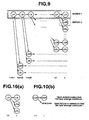
- the microcomputer allows a parent imaginary driver (Series 1) to retain a lane-keeping intention (LK) at every point in time. Further, at every point in time with the parent imaginary driver having a lane-keeping intention (LK), the microcomputer generates data related to two additional imaginary drivers having lane-change intentions to the right (LCR) and to the left (LCL), respectively, for the next point in time.
- an additional imaginary driver generated at a specific point of time assumes at least some of the intentions for all points of time preceding the specific point, from the parent imaginary driver.
- Fig. 10(a) illustrates a first rule for assigning intentions to imaginary drivers.
- the first rule allows the parent imaginary user to retain a lane-keeping intention (LK) at every point in time, and generates data related to two additional imaginary drivers having lane-change intentions (LCR) and (LCL), respectively, at the next point in time.
- Fig. 10(b) illustrates a second rule for assigning intentions to imaginary drivers.
- an imaginary driver is allowed to retain a lane-change intention to the right (LCR) at the next point in time if it is determined that the real driver continues to retain a lane-changing intention at the present point in time.
- an imaginary driver is not allowed to retain a lane-change intention to the right (LCR) at the next point in time .
- This second rule is equally applicable to a lane-change intention to the left (LCL).
- an imaginary driver having a lane-change intention to the left (LCL) at a specific point in time is allowed to retain a lane-change intention to the left (LCL) at the next point in time upon determination that a lane change continues, but the imaginary driver is not allowed to continue to retain a lane-change intention to the left (LCL) at a specific point in time upon failure to determine that the lane change continues. Therefore, according to the second rule, an imaginary driver that has one of the derivative lane-change intentions (LCR) and (LCL), is allowed to retain the derivative lane-change intention at the next point in time upon determination that a lane change continues.
- the microcomputer determines that the lane-change intention continues if the vehicle continues to stay in the same lane.
- the microcomputer determines that the lane-change intention has been realized.if the vehicle has changed to a different lane. In other words, the microcomputer fails to determine that the lane-change intention continues.
- an imaginary driver having one of the derivative lane-change intentions (LCR) and (LCL) at a specific point in time is allowed to retain the lane-change intention at the next point in time upon determination that the vehicle continues to stay in the same lane.
- an imaginary driver that has one of the derivative lane-change intentions (LCR) and (LCL) at a specific point in time is not allowed to retain the derivative lane-change intention at the next point in time upon determination that the vehicle has changed to a different lane.
- an additional imaginary driver that has at least one derivative lane-change intention (LCR) or (LCL) at a specific point in time is terminated and reset at the next point in time upon determination that the vehicle has changed to a different lane.
- the parent driver retains a parent series of lane-keeping intentions (LK), labeled "SERIES 1" in Fig. 9 .
- the parent series of intentions consists of m (m is a natural number) lane-keeping intentions (LK) associated with a period of time ranging from the present point in time (t) back to the past point in time (t -m + 1).
- the parent series of intentions will not be reset.
- the derivative series of intentions (such as Series 2) retained by additional imaginary drivers may be terminated and reset.
- Each of the derivative series of intentions consists of m (m is a natural number) intentions including a lane-change intention (LCR) or (LCL) and its predecessors.
- LCR lane-change intention
- LCL lane-change intention
- the number of additional imaginary drivers that retain derivative series of intentions amounts to 2(m -1) + 1 and but will not exceed this number because any additional imaginary driver that retains a derivative series of intentions would not survive if the number of intentions it retains exceeds m.
- the total number of additional imaginary drivers remains unchanged, but they disappear one after another and are replaced by new ones.
- the parent imaginary driver designed to behave as directed by the parent series of intentions, will not disappear.
- the number of additional imaginary drivers that behave as directed by the derivative series of intentions drops rapidly down to two (2) upon determination that the vehicle has changed lanes, and increases gradually to 2(m -1) + 1 within a predetermined number of points in time.
- frame number m is 20 and the processing speed of the microcomputer is 0.1 second so the cycling time is 2 second.
- the microcomputer calculates a likelihood value Pid(t) for each of the imaginary drivers of the dynamic family.
- the calculated likelihood values for the imaginary drivers are stored at different memory portions at locations labeled with numbers given to the parent series and the derivative series and expressed as Pid(j)(t), where j is a number (an integer) given to one of the parent and derivative series.
- Pid(j)(t) means a calculated likelihood value for an imaginary driver that is designed to behave as directed by an intention of a series j existing at a point in time t.
- the different memory locations are distinguishable one after another with the numbers given to the parent series and the existing derivative series.
- Each of the memory portions has m (m is a natural number) locations to store a series of m likelihood values calculated for one of the imaginary drivers at past and present points in time ranging from the present point in time indicated by (t) back to the past point in time indicated by (t -m + 1).
- the calculated likelihood values for the parent imaginary driver are stored at locations indicated at Pid(1)(t), Pid(1)(t -1) ...
- Pid(1)(t -m + 1) and the calculated likelihood values for the imaginary driver designed to behave as directed by the derivative series "SERIES 2" are stored at locations indicated at Pid(2)(t), Pid(2)(t -1) ... , and Pid(2)(t - m + 1) as illustrated in Fig. 11 .
- the microcomputer calculates a collective likelihood value P(j)ids for each imaginary driver that is designed to behave as directed by intentions of one series, which may be labeled "SERIES j", selected out of the parent and derivative series.
- the equation Eq. 11 states that the likelihood value P(j)ids is the product of all of the calculated likelihood values stored at locations Pid(j)(t) ⁇ Pid(j)(t -m + 1).
- a likelihood value P(1)ids for the parent imaginary driver designed to behave as directed by the lane-keeping intentions (LK) over the a period (t) ⁇ (t -m + 1) of the parent series "SERIES 1" is given as the product of likelihood values Pid.lk(t) ⁇ Pid.lk(t -m + 1).
- a likelihood value P(2)ids for the imaginary driver designed to behave as directed by the lane-change intention to the right (LCR) at the point in time (t) and the lane-keeping intentions (LK) over the time period (t -1) ⁇ (t -m + 1) of the derivative series "SERIES 2" is given as the product of likelihood values Pid.lcr(t), Pid.lk(t -1) ⁇ Pid.lk(t -m + 1).
- the microcomputer calculates the collective likelihood values P(j)ids for the parent imaginary driver designed to behave as directed by intentions of the parent series "SERIES 1" and all of the other imaginary drivers, each designed to behave as directed intentions of one of the existing derivative series. After calculating them, the logic goes to step S307.
- the microcomputer estimates an intention ⁇ rd of the real driver.
- the microcomputer chooses one of the imaginary driver's intentions having the maximum value among the calculated collective likelihood values P(j)ids as the intention ⁇ rd of the real driver.
- the microcomputer provides, as an output, the estimated real driver's intention ⁇ rd.
- this exemplary implementation provides effects as follows:
- steering angles ⁇ rd and ⁇ id were used as operations Ord and Oid of the real and imaginary drivers.
- the present disclosure is not limited to this example.
- Another example is to use an accelerator pedal stroke instead of a steering angle.
- an accelerator pedal stroke Sid of an imaginary driver may be calculated based on a degree to which the vehicle has approached the preceding vehicle. This degree may be expressed by distance to the preceding vehicle and time headway THW.
- a likelihood value of the accelerator pedal stroke Sid with respect to an accelerator pedal stroke Srd of a real driver is calculated for use in estimating a real driver's intention.
- FIG. 12 an exemplary implementation of a driver assisting system 100 according to the present disclosure is described.
- Fig. 13 an exemplary automobile is installed with the driver assisting system 100.
- the driver assisting system 100 includes a laser radar 110.
- the laser radar 110 is mounted to the vehicle at a front bumper or a front grille thereof. It scans horizontally and laterally about 6 degrees to each side of an axis parallel to the vehicle longitudinal centerline, propagates infrared pulses forwardly and receives the reflected radiation by an obstacle, such as, a rear bumper of a preceding vehicle.
- the laser radar 110 can provide a distance d to a preceding vehicle in front and a relative speed Vr to the preceding vehicle.
- the laser radar 110 provides, as outputs, the detected distance d and relative speed Vr to a controller 150.
- the driver assisting system 100 also includes a front camera 120.
- the front camera 120 is of the CCD type or CMOS type and mounted to the vehicle in Fig. 13 in the vicinity of the internal rear view mirror to acquire image data of a region in front of the vehicle.
- the front camera 120 provides, as output signals, the acquired image data to an image processor 130.
- the image processor 130 provides the processed image data to the controller 150.
- the region covered by the front camera 120 extends from the camera axis to each side by 30 degrees.
- the driver assisting system 100 also includes a vehicle speed sensor 140.
- the vehicle speed sensor 140 may determine a vehicle speed of the host vehicle by processing outputs from wheel speed sensors.
- the vehicle speed sensor 140 may include an engine controller or a transmission controller, which can provide a signal indicative of the vehicle speed.
- the vehicle speed sensor 140 provides, as an output, the vehicle speed of the host vehicle to the controller 150.
- the driver assisting system 100 also includes a driver's intention estimating system.
- the driver's intention estimating system 1 or 2 or 3, which are illustrated in Figs. 1 to 11 , may be used in the driver assisting system 100 to provide, as an output, an estimated real driver's intention ⁇ rd to the controller 150.
- the controller 150 which is responsible for information processing within the driver assisting system 100, may contain a microprocessor including a central processing unit (CPU), a read only memory (ROM), and a random access memory (RAM).
- the controller 150 includes, for example, software implementation of a risk potential (RP) calculator 151, a reaction force instruction value FA calculator 152 for applying a reaction force to a driver's control input device, such as an acceleration pedal or a steering wheel, and an instruction value FA correcting section 153.
- RP risk potential
- the RP calculator 151 calculates a risk potential (RP) that may perceived by a real driver in connection with the vehicle's environment based on a vehicle speed V1 of the host vehicle, a distance D to the preceding vehicle, and a relative speed Vr to the preceding vehicle, which are given by processing output signals of the laser radar 110, vehicle speed sensor 140 and image processor 130.
- the RP calculator 151 provides, as an output, the risk potential RP to the accelerator pedal reaction force instruction value FA calculator 152.
- the accelerator pedal reaction force instruction value FA calculator 152 calculates an accelerator pedal reaction force instruction value FA based on the risk potential RP.
- the accelerator pedal reaction force instruction value FA calculator 152 provides, as an output, the accelerator pedal reaction force instruction value FA to the instruction value FA correcting section 153.
- the instruction value FA correcting section 153 corrects the accelerator pedal reaction force instruction value FA based on the estimated driver's intention ⁇ rd to give a corrected accelerator pedal reaction force instruction value FAc.
- the instruction value FA correcting section 153 provides, as an output, the corrected accelerator pedal reaction force instruction value FAc to an accelerator pedal reaction force control unit 170.
- the accelerator pedal reaction force control unit 170 regulates a servo motor 180 of an accelerator pedal 160.
- the accelerator pedal 160 has a link mechanism including a servo motor 180 and an accelerator pedal stroke sensor 181.
- the servo motor 180 may provide any desired torque and any desired angular position in response to an instruction from the accelerator pedal reaction force control unit 170.
- the accelerator pedal stroke sensor 181 detects an accelerator pedal stroke or position S of the accelerator pedal 160 by measuring an angle of the servo motor 180. The angle of the servo motor 180 corresponds to the accelerator pedal stroke S because the servo motor 180 and the accelerator pedal 160 are interconnected by the link mechanism.
- reaction force control unit 170 When the accelerator pedal reaction force control unit 170 is not altering the reaction force, the reaction force increases linearly as the accelerator pedal stroke S increases.
- This ordinary reaction force varying characteristic is accomplished by a spring force provided by a torque spring arranged at the center of rotational movement of the accelerator pedal 160.
- Fig. 15 illustrates a control routine of a driver assisting control program stored in the controller 150.
- the execution of the control routine is repeated at a regular interval of, for example, 50msec.
- the controller 150 recognize environment in a field around the host vehicle.
- the controller 150 receives, as inputs, signals of the laser radar 110, front camera 120 and vehicle speed sensor 140 by reading operations to acquire data regarding the vehicle's status and the vehicle's environment.
- Imaging a traffic scene where the host vehicle is following the preceding vehicle for example, the acquired data include a vehicle speed V1 of the host vehicle, a vehicle speed V2 of the preceding vehicle, and a relative speed to the preceding vehicle Vr.
- the acquired data may include a coordinate X1 of the host vehicle and a coordinate X2 of the preceding vehicle, and a distance D to the preceding vehicle.
- the controller 150 calculates a risk potential RP by the driver from the preceding vehicle based on a time to collision TTC and a time headway THW, which are used as two notions to constitute the risk potential RP.
- the TTC is a measure of time from a present or current moment to a future moment when the distance D would become zero if the relative speed Vr to the preceding vehicle remains unaltered,
- TTC The smaller the value of TTC, the more imminent is the collision and the larger is the value of an extent the vehicle has approached the preceding vehicle.
- the TTC In the traffic scene where the host vehicle is following the preceding vehicle, most vehicle drivers perceived a high degree of risk and initiated deceleration to avoid collision well before the TTC becomes less than 4 seconds.
- the TTC is a good indication for predicting a future behavior the vehicle driver might take.
- the degree of risk which the vehicle driver actually perceives, there is discrepancy between the TTC and the degree of risk.
- the TTC alone is insufficient to quantify the degree of risk.
- Such discrepancy may be confirmed by considering a traffic scene where the relative speed Vr is zero.
- the TTC is infinite irrespective of how narrow the distance D is.
- the driver perceives an increase in the degree of risk in response to a reduction in the distance D, accounting for an increase in influence on the TTC by an unpredictable drop in a vehicle speed of the preceding vehicle.
- the notion of time headway THW has been introduced to quantify an increase how in influence on the TTC by an unpredictable drop in the vehicle speed of the preceding vehicle.
- the THW is a measure of a timer that is set to count up when the preceding vehicle reaches a point on a road and will be reset subsequently when the following vehicle will reach the same point.
- the vehicle speed V2 of the preceding vehicle may be used instead of the vehicle speed V1 in the above-mentioned equation Eq. 14.
- TTC and THW The relationship between the two notions TTC and THW is such that a change in vehicle speed V2, if any, of the preceding vehicle results in a small change in the TTC when the THW is long, but the same change in vehicle speed V2 of the preceding vehicle results in a large change in the TTC when the THW is short.
- the risk potential RP calculated at step S402 is expressed as a sum of a first extent and a second extent.
- the first extent represents to what degree the vehicle has approached the preceding vehicle.
- the second extent represents to what degree an unpredictable change in vehicle speed V2 of the preceding vehicle might have influence upon the vehicle.
- the first extent may be expressed as a function of the reciprocal of time to collision TTC, and the second extent may be expressed as a function of the reciprocal of time headway THW.
- the controller 150 receives, as an input, an accelerator pedal stroke S by reading operation of the output of the accelerator pedal stroke sensor 181.
- the controller 150 calculates an accelerator pedal reaction force instruction value FA.
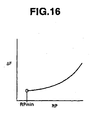
- the controller 150 calculates a reaction force increment ⁇ F in response to the risk potential RP by, for example, referring to the characteristic curve shown in Fig. 16 .
- the curve in Fig. 16 shows varying reaction force increment ⁇ F relative to different values of risk potential RP.
- the reaction force increment ⁇ F is always zero in order to prevent unnecessary information from being presented to the driver.
- An appropriate value is predetermined as the minimum value RPmin.
- reaction force increment ⁇ F increases exponentially as the risk potential RP increases.
- the controller 150 calculates the sum of the reaction force increment ⁇ F and the ordinary reaction force characteristic to provide the accelerator pedal reaction force instruction value FA.
- step S405 the controller 150 determines whether or not the estimated driver's intention ⁇ rd is indicative of a lane-change intention. If this is the case, the logic goes to step S406.
- the controller 150 corrects the accelerator pedal reaction force instruction value FA to give a corrected accelerator pedal reaction force instruction value FAc.
- the accelerator pedal reaction force instruction value FA is processed by a low-pass filter and decreased.
- step S405 the controller 150 determines that the estimated driver's intention ⁇ rd is indicative of a lane-keeping intention, the logic goes to S407.
- the controller 150 sets the accelerator pedal reaction force instruction value FA as the corrected accelerator pedal reaction force instruction value FAc.
- the controller 150 provides, as an output, the corrected accelerator pedal reaction force instruction value FAc that has been determined at step S406 or S407 to the accelerator pedal reaction force control unit 170.
- the accelerator pedal reaction force control unit 170 controls the servo motor 180 in response to the corrected accelerator pedal reaction force instruction value FAc.
- Fig. 17(a) illustrates a traffic scene in which the host vehicle changes lanes to pass the preceding vehicle.
- Fig. 17(b) illustrates two curves: L1 (in solid line) and L2 (in dotted line).
- L2 is a curve showing that the reaction force of the accelerator pedal changing with the value of the risk potential, without considering the real driver's intention.
- the reaction force steadily increases in response to an increased risk potential before the driver actually changes lanes at time tb.
- the increased reaction force tends to interfere with the driver's operation, even if a boost of engine output is eagerly needed by the driver in order to pass the preceding vehicle.
- L1 shows curve with modifying reaction force based on an estimated driver's intention.
- the accelerator pedal reaction force instruction value FAc is modified in response to the estimated driver's lane-change intention.
- the corrected accelerator pedal reaction force instruction value FAc controls the reaction force to drop dramatically to allow a smoother manipulation of the accelerator pedal 160 by the real driver, for the lane-change purpose and the subsequent passing of the preceding vehicle.
- driver assisting system 200 is substantially the same as the driver assisting system 100.
- driver assisting system 200 is different from the driver assisting system 100 in the following respects:
- the driver assisting system 200 corrects a risk potential RP upon determination that the estimated driver's intention ⁇ rd is indicative of a lane-change intention.
- the driver assisting system 200 includes a controller 150A.
- the controller 150A is provided with a software implementation of a risk potential (RP) calculator 151, a risk potential (RP) correcting section 154, and an accelerator pedal reaction force instruction value FA calculator 155.
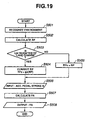
- the flow chart in Fig. 19 illustrates a control routine of a driver assisting control program stored in the controller 150A.
- the execution of the control routine is repeated at a regular interval of, for example, 50msec.
- the flow chart illustrated in Fig. 19 has steps S501 and 502, which correspond to the steps S401 and S402 of the flow chart illustrated in Fig. 15 .
- the controller 150A performs substantially the same jobs down to step S502.
- step S503 the controller 150A determines whether or not the estimated driver's intention ⁇ rd is indicative of a lane-change intention. If this is the case, the logic goes to step S504.
- the controller 150A corrects the risk potential RP to give a corrected risk potential RPc.
- the risk potential RP is processed by a low-pass filter and decreased.
- step S503 the controller 150A determines that the estimated driver's intention ⁇ rd is indicative of a lane-keeping intention, the logic goes to S505.
- the controller 150A sets the risk potential RP as the corrected risk potential RPc.
- the controller 150A receives, as an input, an accelerator pedal stroke S by reading operation of the output of the accelerator pedal stroke sensor 181.
- the controller 150A calculates an accelerator pedal reaction force instruction value FA.
- the controller 150 calculates a reaction force increment ⁇ F in response to the corrected risk potential RPc by, for example, referring to the characteristic curve shown in Fig. 16 .
- the controller 150A calculates the sum of the reaction force increment ⁇ F and the ordinary reaction force characteristic to give an accelerator pedal reaction force instruction value FA.
- the controller 150A provides, as an output, the accelerator pedal reaction force instruction value FA to an accelerator pedal reaction force control unit 170.
- the accelerator pedal reaction force control unit 170 controls a servo motor 180 in response to the accelerator pedal reaction force instruction value FA.
- the controller 150A is provided with the risk potential RP correcting section 154, which can correct or modify the relationship between the obstacle state, including the preceding vehicle, around the host vehicle and the risk potential RP.
- the risk potential RP correcting section 154 decreases the risk potential RP upon determination that the estimated driver's intention is indicative of a lane-change intention, making it possible to decrease the reaction force at an accelerator pedal 160 before the driver actually operates the vehicle as directed by the lane-change intention.
- the driver's intention estimating system 1 is provided for estimating a real driver's intention ⁇ rd
- the driver's intention estimating system 2 or 3 is provided for use in correcting an accelerator pedal reaction force instruction value FA or correcting a risk potential RP in order to alter the accelerator pedal reaction force upon determination that the estimated driver's intention ⁇ rd is indicative of a lane-change intention.
- the risk potential RP was determined by the reciprocal of TTC and the reciprocal of THW. If desired, a risk potential RP might be a function of the reciprocal of TTC only.
Claims (22)
- Système d'estimation d'une intention de conducteur comprenant :un premier dispositif (30) configuré pour détecter une opération d'un conducteur réel d'un véhicule ;un deuxième dispositif (40) configuré pour calculer une valeur de probabilité respective pour chacun d'une pluralité de conducteurs imaginaires en fonction de l'opération de conducteur réel et d'une opération de chacun de la pluralité de conducteurs imaginaires, dans lequel l'opération respective de chacun de la pluralité de conducteurs imaginaires est associée à une intention ; etun troisième dispositif (60) configuré pour déterminer une intention estimée du conducteur réel en fonction de la valeur de probabilité respective de chacun de la pluralité de conducteurs imaginaires,dans lequel l'opération de chacun de la pluralité de conducteurs imaginaires est une intention de maintien de voie, une intention de changement de voie vers la droite ou une intention de changement de voie vers la gauche.
- Système selon la revendication 1, dans lequel le troisième dispositif (60) est configuré pour sélectionner l'un de la pluralité de conducteurs imaginaires en fonction de la valeur de probabilité respective de chacun de la pluralité de conducteurs et pour déterminer l'intention estimée du conducteur réel en fonction de l'intention du conducteur sélectionné de la pluralité de conducteurs imaginaires.
- Système selon la revendication 1, dans lequel :le premier dispositif (30) est configuré pour détecter une opération de conducteur réel à chaque point parmi différents points dans le temps ;le deuxième dispositif (40) est configuré pour générer la valeur de probabilité respective pour chacun de la pluralité de conducteurs imaginaires en fonction de valeurs de probabilité partielles de chacun de la pluralité de conducteurs imaginaires aux différents points dans le temps ; etchacune des valeurs de probabilité partielles est respectivement associée à une opération respective de l'un de la pluralité de conducteurs imaginaires à chacun des différents points dans le temps et est générée en fonction de l'opération détectée respective du conducteur réel à chacun des différents points dans le temps et de l'opération respective de l'un de la pluralité de conducteurs imaginaires à chacun des différents points dans le temps.
- Système selon la revendication 3, dans lequel chaque valeur de probabilité respective pour chacun de la pluralité de conducteurs imaginaires est une sommation respective de valeurs de probabilité partielles de chacun de la pluralité de conducteurs imaginaires aux différents points dans le temps.
- Système selon la revendication 3, dans lequel le deuxième dispositif (40) est configuré pour générer des données relatives à au moins un conducteur imaginaire additionnel à un point dans le temps sélectionné, en fonction de l'intention d'un premier conducteur de la pluralité de conducteurs imaginaires à un point temporel précédant le point temporel sélectionné, dans lequel chacun du au moins un conducteur imaginaire additionnel a une intention et une opération associées à chaque point respectif des différents points dans le temps.
- Système selon la revendication 5, dans lequel l'intention de chacun du au moins un conducteur imaginaire additionnel au point temporel sélectionné est différente de l'intention du premier conducteur de la pluralité de conducteurs imaginaires au point temporel sélectionné et chaque conducteur imaginaire additionnel suppose l'intention associée du premier conducteur de la pluralité de conducteurs imaginaires à chaque point dans le temps précédant le point dans le temps sélectionné.
- Système selon la revendication 5, dans lequel pour chacun des conducteurs imaginaires, le deuxième dispositif (40) est configuré pour générer une intention correspondant à un nouveau point dans le temps en fonction de l'intention respective de chacun des conducteurs imaginaires à un point dans le temps précédant le nouveau point dans le temps.
- Système selon la revendication 5, dans lequel le deuxième dispositif (40) est configuré pour éliminer un conducteur sélectionné de la pluralité de conducteurs imaginaires en fonction d'une intention du conducteur sélectionné de la pluralité de conducteurs imaginaires à un point dans le temps spécifique et d'un état opérationnel du véhicule.
- Véhicule comprenant :un détecteur (10) configuré pour détecter l'environnement autour du véhicule;un premier dispositif (30) configuré pour détecter une opération d'un conducteur réel du véhicule à un point dans le temps ;un deuxième dispositif (40) configuré pour calculer une valeur de probabilité respective pour chacun d'une pluralité de conducteurs imaginaires en fonction de l'opération de conducteur réel et d'une opération de chacun de la pluralité de conducteurs imaginaires dans l'environnement détecté, dans lequel l'opération respective de chacun de la pluralité de conducteurs imaginaires est associée à une intention ; etun troisième dispositif (60) configuré pour déterminer une intention estimée du conducteur réel en fonction de la valeur de probabilité respective de chacun de la pluralité de conducteurs imaginaires,dans lequel l'opération de chacun de la pluralité de conducteurs imaginaires est une intention de maintien de voie, une intention de changement de voie vers la droite ou une intention de changement de voie vers la gauche.
- Procédé d'estimation d'une intention de conducteur comprenant les étapes consistant à :détecter une opération d'un conducteur réel d'un véhicule ;calculer une valeur de probabilité respective pour chacun d'une pluralité de conducteurs imaginaires, en fonction de l'opération de conducteur réel et de l'opération de chacun de la pluralité de conducteurs imaginaires, dans lequel l'opération respective de chacun de la pluralité de conducteurs imaginaires est associée à une intention ; etdéterminer une intention estimée du conducteur réel en fonction de la valeur de probabilité respective de chacun de la pluralité de conducteurs imaginaires,dans lequel l'opération de chacun de la pluralité de conducteurs imaginaires est une intention de maintien de voie, une intention de changement de voie vers la droite ou une intention de changement de voie vers la gauche.
- Procédé selon la revendication 10, dans lequel l'étape de détermination comprend les étapes consistant à :sélectionner l'un de la pluralité de conducteurs imaginaires en fonction des valeurs de probabilité respectives ; etdéterminer l'intention estimée du conducteur réel comme étant l'intention du conducteur sélectionné de la pluralité de conducteurs imaginaires.
- Procédé selon la revendication 10, dans lequel :l'étape de détection détecte une opération de conducteur réel à chacun des différents points dans le temps ;chaque valeur de probabilité respective pour chacun de la pluralité de conducteurs imaginaires est générée en fonction de valeurs de probabilité partielles de chacun de la pluralité de conducteurs imaginaires aux différents points dans le temps ; etchacune des valeurs de probabilité partielles est respectivement associée à une opération de l'un de la pluralité de conducteurs imaginaires à chacun des différents points dans le temps et est générée en fonction de l'opération détectée respective du conducteur réel à chacun des différents points dans le temps et de l'opération respective de l'un de la pluralité de conducteurs imaginaires à chacun des différents points dans le temps.
- Procédé selon la revendication 12, dans lequel chaque valeur de probabilité respective pour chacun de la pluralité de conducteurs imaginaires est une sommation respective de valeurs de probabilité partielles de chacun de la pluralité de conducteurs imaginaires aux différents points dans le temps.
- Procédé selon la revendication 12 comprenant en outre l'étape consistant à générer des données relatives à au moins un conducteur imaginaire additionnel à un point dans le temps sélectionné, en fonction de l'intention d'un premier conducteur de la pluralité de conducteurs imaginaires à un point temporel précédant le point temporel sélectionné, dans lequel chacun du au moins un conducteur imaginaire additionnel a une intention et une opération associées à chaque point respectif des différents points dans le temps.
- Procédé selon la revendication 14, dans lequel l'intention de chacun du au moins un conducteur imaginaire additionnel au point temporel sélectionné est différente de l'intention du premier conducteur de la pluralité de conducteurs imaginaires au point temporel sélectionné.
- Procédé selon la revendication 14, dans lequel chaque conducteur imaginaire additionnel suppose l'intention associée du premier conducteur de la pluralité de conducteurs imaginaires à chaque point dans le temps précédant le point dans le temps sélectionné.
- Procédé selon la revendication 14, dans lequel pour chacun des conducteurs imaginaires, un deuxième dispositif (40) est configuré pour générer une intention correspondant à un nouveau point dans le temps en fonction de l'intention respective de chacun des conducteurs imaginaires à un point dans le temps précédant le nouveau point dans le temps.
- Procédé selon la revendication 14, dans lequel un deuxième dispositif (40) est configuré pour éliminer un conducteur sélectionné de la pluralité de conducteurs imaginaires en fonction d'une intention du conducteur sélectionné de la pluralité de conducteurs imaginaires à un point dans le temps spécifique et d'un état opérationnel du véhicule.
- Système d'assistance de conducteur pour un véhicule actionné par un conducteur réel, comprenant :un dispositif d'entrée commandé par un conducteur ;un calculateur de potentiel de risque (151) configuré pour calculer un potentiel de risque relatif au véhicule ;un système d'estimation d'intention de conducteur comprenant :dans lequel l'opération de chacun de la pluralité de conducteurs imaginaires est une intention de maintien de voie, une intention de changement de voie vers la droite ou une intention de changement de voie vers la gauche.un premier dispositif (30) configuré pour détecter une opération de conducteur réel ;un deuxième dispositif (40) configuré pour calculer une valeur de probabilité respective pour chacun d'une pluralité de conducteurs imaginaires en fonction de l'opération de conducteur réel et d'une opération de chacun de la pluralité de conducteurs imaginaires, dans lequel l'opération respective de chacun de la pluralité de conducteurs imaginaires est associée à une intention ; etun troisième dispositif (60) configuré pour déterminer une intention estimée du conducteur réel en fonction de la valeur de probabilité respective de chacun de la pluralité de conducteurs imaginaires,etune unité de régulation de force de réaction (170) configurée pour réguler une force de réaction associée au dispositif d'entrée commandé par un conducteur en fonction du potentiel de risque calculé et de l'intention estimée du conducteur réel,
- Système d'assistance de conducteur selon la revendication 19, dans lequel l'unité de régulation de force de réaction (170) est configurée pour effectuer une régulation initiale sur la force de réaction en fonction du potentiel de risque calculé et pour modifier la régulation initiale en fonction de l'intention estimée du conducteur réel.
- Système d'assistance de conducteur selon la revendication 19, dans lequel l'unité de régulation de force de réaction (170) est configurée pour modifier le potentiel de risque en fonction de l'intention estimée du conducteur réel et pour modifier la force de réaction en fonction du potentiel de risque modifié.
- Support lisible par une machine portant des instructions pour estimer une intention de conducteur, les instructions, lors de leur exécution par un système de traitement de données, amenant le système de traitement de données à effectuer les étapes consistant à :détecter une opération effectuée par un conducteur ;calculer une valeur de probabilité respective pour chacun d'une pluralité de conducteurs imaginaires, en fonction de l'opération effectuée par le conducteur et de l'opération de chacun de la pluralité de conducteurs imaginaires, dans lequel l'opération respective de chacun de la pluralité de conducteurs imaginaires est associée à une intention ; etdéterminer une intention estimée du conducteur réel en fonction de la valeur de probabilité respective de chacun de la pluralité de conducteurs imaginaires,dans lequel l'opération de chacun de la pluralité de conducteurs imaginaires est une intention de maintien de voie, une intention de changement de voie vers la droite ou une intention de changement de voie vers la gauche.
Applications Claiming Priority (2)
| Application Number | Priority Date | Filing Date | Title |
|---|---|---|---|
| JP2003417744A JP4226455B2 (ja) | 2003-12-16 | 2003-12-16 | 運転意図推定装置、車両用運転操作補助装置および車両用運転操作補助装置を備えた車両 |
| JP2003417744 | 2003-12-16 |
Publications (2)
| Publication Number | Publication Date |
|---|---|
| EP1544071A1 EP1544071A1 (fr) | 2005-06-22 |
| EP1544071B1 true EP1544071B1 (fr) | 2008-02-13 |
Family
ID=34510610
Family Applications (1)
| Application Number | Title | Priority Date | Filing Date |
|---|---|---|---|
| EP04029607A Expired - Fee Related EP1544071B1 (fr) | 2003-12-16 | 2004-12-14 | Procédé et dispositif pour estimer l'intention d'un conducteur |
Country Status (4)
| Country | Link |
|---|---|
| US (1) | US7778742B2 (fr) |
| EP (1) | EP1544071B1 (fr) |
| JP (1) | JP4226455B2 (fr) |
| DE (1) | DE602004011739T2 (fr) |
Cited By (4)
| Publication number | Priority date | Publication date | Assignee | Title |
|---|---|---|---|---|
| US10726642B1 (en) | 2019-03-29 | 2020-07-28 | Toyota Motor North America, Inc. | Vehicle data sharing with interested parties |
| US10896555B2 (en) | 2019-03-29 | 2021-01-19 | Toyota Motor North America, Inc. | Vehicle data sharing with interested parties |
| US11100728B2 (en) | 2019-03-29 | 2021-08-24 | Toyota Motor North America, Inc. | Vehicle data sharing with interested parties |
| US11529918B2 (en) | 2019-09-02 | 2022-12-20 | Toyota Motor North America, Inc. | Adjustment of environment of transports |
Families Citing this family (23)
| Publication number | Priority date | Publication date | Assignee | Title |
|---|---|---|---|---|
| JP4062310B2 (ja) | 2005-02-07 | 2008-03-19 | 日産自動車株式会社 | 運転意図推定装置、車両用運転操作補助装置および車両用運転操作補助装置を備えた車両 |
| JP4852851B2 (ja) * | 2005-02-07 | 2012-01-11 | 日産自動車株式会社 | 運転意図推定装置、車両用運転操作補助装置および車両用運転操作補助装置を備えた車両 |
| JP2007022238A (ja) * | 2005-07-14 | 2007-02-01 | Nissan Motor Co Ltd | 車両用運転操作補助装置および車両用運転操作補助装置を備えた車両 |
| JP4740684B2 (ja) | 2005-08-03 | 2011-08-03 | 日産自動車株式会社 | 車両用運転操作補助装置および車両用運転操作補助装置を備えた車両 |
| US8140241B2 (en) | 2005-12-28 | 2012-03-20 | National University Corporation Nagoya University | Driving action estimating device, driving support device, vehicle evaluating system, driver model creating device, and driving action determining device |
| CN1996194A (zh) * | 2005-12-31 | 2007-07-11 | 清华大学 | 一种运动物体定位纠偏系统及其运动跟踪方法 |
| JP4992907B2 (ja) * | 2007-05-02 | 2012-08-08 | トヨタ自動車株式会社 | 車両挙動制御装置 |
| GB2457279A (en) * | 2008-02-08 | 2009-08-12 | Airmax Group Plc | Configuration of an electronic control system for controlling the operation of at least one component of a vehicle |
| US8170739B2 (en) * | 2008-06-20 | 2012-05-01 | GM Global Technology Operations LLC | Path generation algorithm for automated lane centering and lane changing control system |
| DE112009002530T5 (de) | 2008-10-30 | 2012-08-23 | Ford Global Technologies, Llc | Fahrzeug und Verfahren zum Beraten eines Fahrers von selbigen |
| US8738228B2 (en) | 2009-10-30 | 2014-05-27 | Ford Global Technologies, Llc | Vehicle and method of tuning performance of same |
| EP2571004B1 (fr) | 2010-06-18 | 2016-03-09 | Honda Motor Co., Ltd. | Système permettant de déduire une intention de changement de voie d'un conducteur |
| WO2013031095A1 (fr) * | 2011-08-31 | 2013-03-07 | 日産自動車株式会社 | Dispositif d'aide à la conduite d'un véhicule |
| JP5853589B2 (ja) * | 2011-10-26 | 2016-02-09 | 日産自動車株式会社 | 運転支援装置 |
| DE102011121484A1 (de) * | 2011-12-16 | 2013-06-20 | Audi Ag | Bedienungssystem für ein Fahrzeug und Verfahren zur Unterstützung eines Fahrers beim Bedienen eines Fahrzeugs |
| JP6558584B2 (ja) * | 2013-04-12 | 2019-08-14 | ダナ リミテッド | パターン認識による車両及びオペレータガイダンス |
| KR101470146B1 (ko) | 2013-04-23 | 2014-12-05 | 현대자동차주식회사 | 가속페달 장치의 답력 능동 조절방법 |
| DE102014205391A1 (de) * | 2014-03-24 | 2015-09-24 | Bayerische Motoren Werke Aktiengesellschaft | Vorrichtung zur Vorhersage von Fahrzustandsübergängen |
| JP6046190B2 (ja) * | 2015-03-31 | 2016-12-14 | 本田技研工業株式会社 | 運転支援装置 |
| DE102016221565B4 (de) | 2016-11-03 | 2018-05-17 | Ford Global Technologies, Llc | Verfahren zum Unterscheiden zwischen gewollten Lenkbewegungen eines Fahrers zur Beeinflussung eines gewollten Fahrpfades eines Kraftfahrzeuges von Korrekturlenkbewegungen des Fahrers als Reaktion auf unerwartete Abweichungen des Kraftfahrzeuges vom gewollten Fahrpfad sowie maschinenlesbarer Datenträger |
| US10144427B2 (en) | 2017-03-07 | 2018-12-04 | Toyota Motor Engineering & Manufacturing North America, Inc. | Learning driver rate of pedal change |
| US10814913B2 (en) | 2017-04-12 | 2020-10-27 | Toyota Jidosha Kabushiki Kaisha | Lane change assist apparatus for vehicle |
| CN114312793B (zh) * | 2021-12-31 | 2023-07-21 | 上汽大众汽车有限公司 | 一种轨迹模式的匹配方法、匹配系统及计算机可读存储介质 |
Citations (1)
| Publication number | Priority date | Publication date | Assignee | Title |
|---|---|---|---|---|
| US20030167112A1 (en) * | 2002-03-01 | 2003-09-04 | Susumu Akiyama | Vehicle agent system acting for driver in controlling in-vehicle devices |
Family Cites Families (43)
| Publication number | Priority date | Publication date | Assignee | Title |
|---|---|---|---|---|
| US5189621A (en) | 1987-05-06 | 1993-02-23 | Hitachi, Ltd. | Electronic engine control apparatus |
| JP3197307B2 (ja) | 1991-10-14 | 2001-08-13 | マツダ株式会社 | 移動車の走行制御装置 |
| JP3273800B2 (ja) | 1991-11-11 | 2002-04-15 | 茂 近藤 | 自動車運転解析診断方法及び装置 |
| DE4313568C1 (de) | 1993-04-26 | 1994-06-16 | Daimler Benz Ag | Verfahren zur Leithilfe für einen Fahrspurwechsel durch ein Kraftfahrzeug |
| JP3357749B2 (ja) | 1994-07-12 | 2002-12-16 | 本田技研工業株式会社 | 車両の走行路画像処理装置 |
| JPH0872589A (ja) | 1994-09-02 | 1996-03-19 | Hitachi Ltd | パワートレイン制御装置及び制御方法 |
| US6278362B1 (en) | 1995-01-12 | 2001-08-21 | Honda Giken Kogyo Kabushiki Kaisha | Driving state-monitoring apparatus for automotive vehicles |
| DE19536512A1 (de) * | 1995-09-29 | 1997-04-03 | Bayerische Motoren Werke Ag | Gangwechselsteuerung für Automatikgetriebe in Kraftfahrzeugen mit einem elektronischen Steuergerät |
| JP3521249B2 (ja) | 1995-11-24 | 2004-04-19 | 光洋精工株式会社 | 自動車の舵取り装置 |
| JP3599144B2 (ja) | 1996-05-09 | 2004-12-08 | 本田技研工業株式会社 | 車両用操舵支援装置 |
| DE19620929A1 (de) | 1996-05-24 | 1997-11-27 | Porsche Ag | Längsregelsystem für Kraftfahrzeuge mit haptischem Gaspedal |
| JPH1031799A (ja) | 1996-07-15 | 1998-02-03 | Toyota Motor Corp | 自動走行制御装置 |
| EP0819912B1 (fr) | 1996-07-15 | 2004-11-17 | Toyota Jidosha Kabushiki Kaisha | Dispositif pour la prédiction des conditions de conduite de véhicule et dispositif avertisseur utilisant ce dispositif |
| JPH10166934A (ja) | 1996-12-13 | 1998-06-23 | Koito Mfg Co Ltd | 車輌用灯具装置 |
| US6185492B1 (en) | 1997-07-09 | 2001-02-06 | Toyota Jidosha Kabushiki Kaisha | Vehicle steering control apparatus for assisting a steering effort to move a vehicle along a line desired by a driver |
| JP3358709B2 (ja) | 1997-08-11 | 2002-12-24 | 富士重工業株式会社 | 車両用運転支援装置 |
| DE19736756A1 (de) | 1997-08-23 | 1999-02-25 | Volkswagen Ag | Verfahren und Vorrichtung zur Abstandsregelung für ein Fahrzeug |
| JP3314866B2 (ja) | 1997-09-13 | 2002-08-19 | 本田技研工業株式会社 | 車両用操舵装置 |
| JPH11321598A (ja) | 1998-05-07 | 1999-11-24 | Honda Motor Co Ltd | 車両走行安全装置 |
| DE19921449C1 (de) | 1999-05-08 | 2001-01-25 | Daimler Chrysler Ag | Leithilfe bei einem Fahrspurwechsel eines Kraftfahrzeuges |
| JP3998855B2 (ja) | 1999-05-18 | 2007-10-31 | 三菱電機株式会社 | 危険接近防止装置 |
| JP4120127B2 (ja) * | 2000-02-23 | 2008-07-16 | アイシン・エィ・ダブリュ株式会社 | 自動変速機の制御装置 |
| JP3539362B2 (ja) | 2000-07-07 | 2004-07-07 | 日産自動車株式会社 | 車線追従走行制御装置 |
| JP3498910B2 (ja) | 2000-09-05 | 2004-02-23 | 日産自動車株式会社 | 車線追従制御装置 |
| JP3603768B2 (ja) | 2000-09-06 | 2004-12-22 | 日産自動車株式会社 | 車線逸脱判定装置 |
| JP2004508627A (ja) | 2000-09-08 | 2004-03-18 | レイセオン・カンパニー | 経路予測システムおよび方法 |
| JP3600518B2 (ja) | 2000-10-11 | 2004-12-15 | トヨタ自動車株式会社 | 車両用変速制御装置 |
| US6879969B2 (en) * | 2001-01-21 | 2005-04-12 | Volvo Technological Development Corporation | System and method for real-time recognition of driving patterns |
| JP2002331850A (ja) | 2001-05-07 | 2002-11-19 | Nissan Motor Co Ltd | 運転行動意図検出装置 |
| EP1256479A1 (fr) | 2001-05-07 | 2002-11-13 | Ford Global Technologies, Inc., A subsidiary of Ford Motor Company | Procédé pour évaluer le mode de conduite d'un véhicule |
| EP1285842B1 (fr) | 2001-08-23 | 2008-05-28 | Nissan Motor Co., Ltd. | Système d'assistance à la conduite |
| DE50312682D1 (de) * | 2002-03-21 | 2010-06-17 | Continental Automotive Gmbh | Verfahren zum Steuern eines automatischen Getriebes |
| FR2838386B1 (fr) | 2002-04-11 | 2004-06-18 | Renault Sa | Procede et dispositif d'activation automatique d'un regulateur de vitesse pour vehicule |
| US6879896B2 (en) | 2002-04-11 | 2005-04-12 | Delphi Technologies, Inc. | System and method for using vehicle operator intent to adjust vehicle control system response |
| JP4173324B2 (ja) | 2002-06-20 | 2008-10-29 | 日産自動車株式会社 | アクセルペダル装置 |
| JP3700682B2 (ja) | 2002-06-20 | 2005-09-28 | 日産自動車株式会社 | アクセルペダル装置 |
| JP3838166B2 (ja) | 2002-06-20 | 2006-10-25 | 日産自動車株式会社 | 車両用運転操作補助装置 |
| JP3938023B2 (ja) | 2002-11-27 | 2007-06-27 | 日産自動車株式会社 | リスクポテンシャル算出装置、車両用運転操作補助装置、その装置を備える車両およびリスクポテンシャル演算方法 |
| JP4561092B2 (ja) * | 2003-12-16 | 2010-10-13 | 日産自動車株式会社 | 車両用運転操作補助装置および車両用運転操作補助装置を備えた車両 |
| JP4281543B2 (ja) * | 2003-12-16 | 2009-06-17 | 日産自動車株式会社 | 車両用運転操作補助装置および車両用運転操作補助装置を備えた車両 |
| JP4229051B2 (ja) * | 2004-11-26 | 2009-02-25 | 日産自動車株式会社 | 運転意図推定装置、車両用運転操作補助装置および車両用運転操作補助装置を備えた車両 |
| JP4062310B2 (ja) * | 2005-02-07 | 2008-03-19 | 日産自動車株式会社 | 運転意図推定装置、車両用運転操作補助装置および車両用運転操作補助装置を備えた車両 |
| DE102005018688A1 (de) * | 2005-04-22 | 2006-10-26 | Bayerische Motoren Werke Ag | Fahrerassistenzsystem |
-
2003
- 2003-12-16 JP JP2003417744A patent/JP4226455B2/ja not_active Expired - Fee Related
-
2004
- 2004-12-14 EP EP04029607A patent/EP1544071B1/fr not_active Expired - Fee Related
- 2004-12-14 DE DE602004011739T patent/DE602004011739T2/de active Active
-
2008
- 2008-02-08 US US12/068,584 patent/US7778742B2/en not_active Expired - Fee Related
Patent Citations (1)
| Publication number | Priority date | Publication date | Assignee | Title |
|---|---|---|---|---|
| US20030167112A1 (en) * | 2002-03-01 | 2003-09-04 | Susumu Akiyama | Vehicle agent system acting for driver in controlling in-vehicle devices |
Cited By (6)
| Publication number | Priority date | Publication date | Assignee | Title |
|---|---|---|---|---|
| US10726642B1 (en) | 2019-03-29 | 2020-07-28 | Toyota Motor North America, Inc. | Vehicle data sharing with interested parties |
| US10896555B2 (en) | 2019-03-29 | 2021-01-19 | Toyota Motor North America, Inc. | Vehicle data sharing with interested parties |
| US11100728B2 (en) | 2019-03-29 | 2021-08-24 | Toyota Motor North America, Inc. | Vehicle data sharing with interested parties |
| US11328540B2 (en) | 2019-03-29 | 2022-05-10 | Toyota Motor North America, Inc. | Vehicle data sharing with interested parties |
| US11869281B2 (en) | 2019-03-29 | 2024-01-09 | Toyota Motor North America, Inc. | Vehicle data sharing with interested parties |
| US11529918B2 (en) | 2019-09-02 | 2022-12-20 | Toyota Motor North America, Inc. | Adjustment of environment of transports |
Also Published As
| Publication number | Publication date |
|---|---|
| DE602004011739D1 (de) | 2008-03-27 |
| US7778742B2 (en) | 2010-08-17 |
| US20080147249A1 (en) | 2008-06-19 |
| EP1544071A1 (fr) | 2005-06-22 |
| DE602004011739T2 (de) | 2009-03-05 |
| JP2005182123A (ja) | 2005-07-07 |
| JP4226455B2 (ja) | 2009-02-18 |
Similar Documents
| Publication | Publication Date | Title |
|---|---|---|
| EP1544071B1 (fr) | Procédé et dispositif pour estimer l'intention d'un conducteur | |
| US7349767B2 (en) | Method and system for intention estimation and operation assistance | |
| EP1544070B1 (fr) | Procédé et dispositif pour éstimer l'intention du conducteur d'un véhicule avec indication de fiabilité | |
| EP1602542B1 (fr) | Procédé et dispositif adaptatives pour estimer l'intention de l'opérateur d'un véhicule automobile | |
| EP1544022B1 (fr) | Dispositif et méthode d'assistance d'un opérateur | |
| EP1661751B1 (fr) | Système d'estimation des intentions du conducteur d'un véhicule, système d'assistance et véhicule pourvu d'un tel système | |
| US7403842B2 (en) | Driver assisting system | |
| US7634331B2 (en) | Driving intention estimation system, vehicle operation assistance system, and vehicle equipped therewith | |
| EP1720726B1 (fr) | Procede et systeme d'assistance pour un conducteur de vehicule conduisant un vehicule sur une route | |
| US9771070B2 (en) | Method and system for controlling a host vehicle | |
| US8849515B2 (en) | Steering assist in driver initiated collision avoidance maneuver | |
| US7715972B2 (en) | Driving assisting system for a vehicle and a vehicle installed with the system | |
| US7630818B2 (en) | Intelligent driving assistance method and system | |
| JP4927056B2 (ja) | 運転意図推定装置、車両用運転操作補助装置および車両用運転操作補助装置を備えた車両 |
Legal Events
| Date | Code | Title | Description |
|---|---|---|---|
| PUAI | Public reference made under article 153(3) epc to a published international application that has entered the european phase |
Free format text: ORIGINAL CODE: 0009012 |
|
| 17P | Request for examination filed |
Effective date: 20041214 |
|
| AK | Designated contracting states |
Kind code of ref document: A1 Designated state(s): AT BE BG CH CY CZ DE DK EE ES FI FR GB GR HU IE IS IT LI LT LU MC NL PL PT RO SE SI SK TR |
|
| AX | Request for extension of the european patent |
Extension state: AL BA HR LV MK YU |
|
| AKX | Designation fees paid |
Designated state(s): DE FR GB |
|
| 17Q | First examination report despatched |
Effective date: 20051102 |
|
| GRAP | Despatch of communication of intention to grant a patent |
Free format text: ORIGINAL CODE: EPIDOSNIGR1 |
|
| GRAS | Grant fee paid |
Free format text: ORIGINAL CODE: EPIDOSNIGR3 |
|
| GRAA | (expected) grant |
Free format text: ORIGINAL CODE: 0009210 |
|
| AK | Designated contracting states |
Kind code of ref document: B1 Designated state(s): DE FR GB |
|
| REG | Reference to a national code |
Ref country code: GB Ref legal event code: FG4D |
|
| REF | Corresponds to: |
Ref document number: 602004011739 Country of ref document: DE Date of ref document: 20080327 Kind code of ref document: P |
|
| ET | Fr: translation filed | ||
| PLBE | No opposition filed within time limit |
Free format text: ORIGINAL CODE: 0009261 |
|
| STAA | Information on the status of an ep patent application or granted ep patent |
Free format text: STATUS: NO OPPOSITION FILED WITHIN TIME LIMIT |
|
| 26N | No opposition filed |
Effective date: 20081114 |
|
| REG | Reference to a national code |
Ref country code: FR Ref legal event code: PLFP Year of fee payment: 12 |
|
| PGFP | Annual fee paid to national office [announced via postgrant information from national office to epo] |
Ref country code: DE Payment date: 20151208 Year of fee payment: 12 Ref country code: GB Payment date: 20151209 Year of fee payment: 12 |
|
| PGFP | Annual fee paid to national office [announced via postgrant information from national office to epo] |
Ref country code: FR Payment date: 20151110 Year of fee payment: 12 |
|
| REG | Reference to a national code |
Ref country code: DE Ref legal event code: R119 Ref document number: 602004011739 Country of ref document: DE |
|
| GBPC | Gb: european patent ceased through non-payment of renewal fee |
Effective date: 20161214 |
|
| REG | Reference to a national code |
Ref country code: FR Ref legal event code: ST Effective date: 20170831 |
|
| PG25 | Lapsed in a contracting state [announced via postgrant information from national office to epo] |
Ref country code: FR Free format text: LAPSE BECAUSE OF NON-PAYMENT OF DUE FEES Effective date: 20170102 |
|
| PG25 | Lapsed in a contracting state [announced via postgrant information from national office to epo] |
Ref country code: GB Free format text: LAPSE BECAUSE OF NON-PAYMENT OF DUE FEES Effective date: 20161214 Ref country code: DE Free format text: LAPSE BECAUSE OF NON-PAYMENT OF DUE FEES Effective date: 20170701 |