EP1544031A2 - Spannvorrichtung für Gurte - Google Patents
Spannvorrichtung für Gurte Download PDFInfo
- Publication number
- EP1544031A2 EP1544031A2 EP04292768A EP04292768A EP1544031A2 EP 1544031 A2 EP1544031 A2 EP 1544031A2 EP 04292768 A EP04292768 A EP 04292768A EP 04292768 A EP04292768 A EP 04292768A EP 1544031 A2 EP1544031 A2 EP 1544031A2
- Authority
- EP
- European Patent Office
- Prior art keywords
- link
- section
- longitudinal
- flexible
- longitudinally
- Prior art date
- Legal status (The legal status is an assumption and is not a legal conclusion. Google has not performed a legal analysis and makes no representation as to the accuracy of the status listed.)
- Granted
Links
- 125000006850 spacer group Chemical group 0.000 claims description 20
- 230000005489 elastic deformation Effects 0.000 claims description 4
- 239000000543 intermediate Substances 0.000 description 37
- 238000006073 displacement reaction Methods 0.000 description 4
- 230000035939 shock Effects 0.000 description 4
- 210000004027 cell Anatomy 0.000 description 2
- 239000000463 material Substances 0.000 description 2
- 241000270295 Serpentes Species 0.000 description 1
- 230000003247 decreasing effect Effects 0.000 description 1
- 230000000694 effects Effects 0.000 description 1
- 239000002184 metal Substances 0.000 description 1
- 230000002093 peripheral effect Effects 0.000 description 1
- 230000000717 retained effect Effects 0.000 description 1
- 238000004904 shortening Methods 0.000 description 1
Images


Classifications
-
- B—PERFORMING OPERATIONS; TRANSPORTING
- B60—VEHICLES IN GENERAL
- B60P—VEHICLES ADAPTED FOR LOAD TRANSPORTATION OR TO TRANSPORT, TO CARRY, OR TO COMPRISE SPECIAL LOADS OR OBJECTS
- B60P7/00—Securing or covering of load on vehicles
- B60P7/06—Securing of load
- B60P7/08—Securing to the vehicle floor or sides
- B60P7/0823—Straps; Tighteners
- B60P7/0861—Measuring or identifying the tension in the securing element
-
- B—PERFORMING OPERATIONS; TRANSPORTING
- B60—VEHICLES IN GENERAL
- B60P—VEHICLES ADAPTED FOR LOAD TRANSPORTATION OR TO TRANSPORT, TO CARRY, OR TO COMPRISE SPECIAL LOADS OR OBJECTS
- B60P7/00—Securing or covering of load on vehicles
- B60P7/06—Securing of load
- B60P7/16—Protecting against shocks
Definitions
- the invention generally relates to devices for maintaining tension of flexible links, especially for load securing devices on vehicles automobiles.
- Lashing devices such as bike racks usually include fastening straps equipped with loops to put these straps in tension.
- Vehicle movements cause shocks and vibrations that can cause in the long run a slipping straps in loops and loosening the tension of these straps.
- the charges retained by the straps can then flop and damage the bodywork of the vehicle, and even, in extreme cases, break away.
- the present invention aims to to propose a device to maintain such straps in tension over a long time, despite shocks and vibrations.
- the tension holding device of a flexible link of elongated form of the invention is adapted to be arranged on a longitudinal section of said link and conform this stretch so that this one occupies a longitudinal length of rest when the link is not energized, the device cooperating with the flexible link so that the tensioning of the link causes an increase in longitudinal length occupied by said section by elastic deformation of the holding device.
- the longitudinal section of the link forms the minus one fold in a vertical direction perpendicular to the longitudinal direction when the device is arranged on said section, this fold having a rest height when the link is not switched on, the power up of the link causing a reduction of this height.
- the longitudinal stretch of the link can also form a plurality of parallel vertical folds when the device is arranged on said section.
- the device comprises two pivotal basic elements aligned longitudinally, and a intermediate pivot element located longitudinally between the basic pivots and shifted vertically by in relation to these, the intermediate pivot being connected to the basic pivots by spacers Flexible.
- the device may also include a plurality of aligned basic pivot elements longitudinally, and a plurality of pivotal elements intermediaries located longitudinally each between two basic pivots and offset vertically by relationship to these, each intermediate pivotal element being connected to the two base pivots contiguous with flexible spacers.
- the device may comprise two deformable base plates elastically arranged mutually opposite, and at least three studs extending in a transverse direction perpendicular to the longitudinal and vertical directions and connecting the two base plates, these pads being at less partially aligned longitudinally at rest and having a large section relative to the vertical thickness of the flexible link.
- the section of the flexible link forms at least one turn wrapped around a longitudinal axis when the device is arranged on said section, this turn having a no rest when the link is not powered, the power up the link causing an increase in this not.
- the device comprises a sleeve longitudinal elastically deformable according to the longitudinal direction, on which the section is wound of the link.
- the sleeve is delimited by a face radial and two opposite axial faces, the sleeve including two oblique lights putting in communication the two opposite axial faces with the radial face.
- the link can be a strap of thin in the vertical direction, a thin plate following the direction vertical, or a wire.
- the device is adapted to be arranged on two longitudinal sections superimposed on the link flexible.
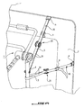
- FIGS. 1 to 14 a The device represented in FIGS. 1 to 14 a for the purpose of maintaining in tension a flexible link 10 of elongated, non-elastic form.
- this link 10 is example a strap for holding a door frame bicycles 1 rigidly attached to the tailgate 2 of a motor vehicle.
- a tensioning loop 3 is climb to a first end of this link, this one being then passed through a ring 4 secured to the frame 1, and finally coming into a slot of passage of loop 3, so that the link part 10 the closer to the loop 3 forms a closed collar 5.
- link 10 can also be spent around a frame amount 1 and not in a ring 4.
- a hook 6 is slidably mounted along the collar 5 and is engaged in the groove that surrounds the tailgate 2 and marks the solution of continuity between this tailgate and the rest of the bodywork.
- Link 10 is put in tension by pulling on its opposite end to the loop 3, which has the effect of sliding the link in the loop 3 slot and tighten the collar 5 until this collar is stretched between hook 6 and the ring 4.
- a unidirectional locking device mounted on the loop 3 allows the sliding of the link 10 in the slot in the direction of a tightening of the collar 5, and blocks the sliding of the link 10 in the slot in the meaning of a loosening of the collar 5.
- frame 1 is stowed on the tailgate 2 using several links of this type extending into opposite directions. Once the tensioning of the different links 10 carried out, frame 1 is securely secured to the vehicle.
- the collar 5 adopts a generally rectilinear shape because of the voltage, having two parallel branches 51 and integral, each extending between the hook 6 and the ring 4.
- the voltage maintaining device 20 of the invention is distinct from the tensioning loop 3 and mounts on link 10 in addition to this loop 3. It aims to compensate for the slippage of the link 10 in the slot of the loop 3 in the direction of a loosening of the collar 5 that can occur at the long. For this purpose, it compensates for the lengthening of peripheral length of the collar 5 resulting from the slip, causing a shortening of the collar practically equivalent in another point.
- the holding device 20 is adapted to be arranged on a longitudinal section 11 of said link part of the collar 5. In the absence of the device 20 of maintaining tension, this section has a shape rectilinear and a given longitudinal length said intrinsic.
- the device 20 cooperates with the link flexible 10 so that the tensioning of the link 10 causes an increase in longitudinal length occupied by said section 11 by elastic deformation of the holding device 20.
- a slip of the link 10 in the slot of the loop 3 will lead to a reduction in the voltage of the link in the collar 5, this voltage reduction decreasing the elastic deformation of the device holding 20 and leading to a decrease in length length of section 11.
- the elasticity of the holding device 20 is chosen so that the reduction in length of the section 11 compensates approximately the lengthening of the collar 5 due to sliding of the link 10 in the loop. The tension of the necklace 5 therefore remains substantially constant despite the sliding.
- the longitudinal section 11 of the link 10 forms, when the voltage holding device 20 is arranged on said section, at least one fold 12 protruding from the longitudinal direction in one direction vertically perpendicular to the longitudinal direction.
- This fold 12 has a vertical height of rest when the link 10 is not powered up, putting the link voltage 10 causing a reduction of this height.
- Fold 12 makes the longitudinal length of rest of section 11 is less than its length intrinsic. Moreover, we understand that reduction in the height of fold 12 resulting from the tension of the link 10 necessarily leads to a lengthening of the longitudinal length occupied by the section 11.
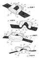
- the first embodiment of the device of voltage maintaining 20, shown in FIGS. 1 to 3, allows for a single fold 12.
- This device is monobloc and includes two basic pivot elements 21 longitudinally aligned, and an intermediate pivot element 22 located longitudinally between the basic pivot elements 21 and offset vertically on one side of section 11 with respect to them.
- the basic pivot elements 21 and the element intermediate 22 are cylindrical bars identical, extending in a transverse direction perpendicular to the longitudinal directions and transversal, and therefore mutually parallel.
- the intermediate element 22 is located in a plane transversal median of the two basic elements 21.
- the intermediate pivot element 22 is connected to basic pivot elements 21 by spacers flexible 23.
- spacers 23 are in the form of bars inclined, two parallel spacers 23 connecting the opposite transverse ends of the element intermediate 22 at the opposite transverse ends of one of the basic elements 21, and two other spacers 23 parallels connecting the transverse ends opposite of the intermediate element 22 at the ends opposite cross-section of the other basic element.
- two spacers 23 form with the base member 21 corresponding and the intermediate element 22 a parallelogram.
- the holding device 20 has a shape in V, the intermediate element 22 occupying the tip of the V, the basic elements 21 constituting its extremities free, and the spacers 23 constituting the two arms V.
- Figure 2 shows how the device voltage maintaining device 20 is arranged on the link 10, this link not yet put in tension.
- the section 11 extends first longitudinally, passes a side of the first base element 21 opposite the element intermediate 22, pivots around this first element of base 21 and extends substantially between the two spacers 23 to the intermediate element 22, pivots around the intermediate element 22 of an outer side of it, that is to say opposed to the basic elements 21, then extends substantially between the other two spacers 23 to the second base member 21, pivots around the second base element 21 going from one side of it opposite the intermediate element 22, and finally extends longitudinally from the second element of base 21, away from the first base member 21.
- the fold 12 is constituted by the part of the link 10 ranging from the first base element 21 to the element intermediate 22 and returning to the second element of base 21.
- Figures 4 to 6 show a second mode of embodiment of the invention, in which the section longitudinal 11 of the link 10 forms a plurality of folds 12 parallel vertical lines when the device 20 is arranged on said section 11. These folds 12 are spaced apart longitudinally along section 11.
- the voltage holding device 20 comprises in this case a plurality of basic pivot elements 21 aligned longitudinally, and a plurality of elements intermediate pivots 22 located longitudinally each between two basic pivot elements 21 and staggered vertically in relation to these.
- the pivotal elements intermediates 22 are aligned in the direction longitudinal.
- the basic elements 21 and the elements intermediates 22 are bars identical to those of the first embodiment, mutually parallel, all extending transversely.
- Basic elements 21 are regularly spaced longitudinally, likewise that the intermediate elements 22.
- Each element intermediate 22 extends in a median transverse plane of two basic elements. voltage therefore comprises a number of intermediate element 22 less than one unit to the base element number 21.
- the device typically comprises four elements base 21, and three intermediate elements 22.
- Each intermediate pivot element 22 is connected to two pivotal base elements 21 contiguous between which it is located by flexible spacers 23 having each an S shape.
- two parallel spacers 23 connect the ends opposite cross-sections of intermediate element 22 to opposite transverse ends of a base element 21, and two other parallel spacers 23 connect the opposite transverse ends of the element intermediate 22 at the opposite transverse ends of the other basic element 21.
- the two spacers in S 23 integral with the same end of the intermediate element 22 and binding it to the two basic elements 21 are oriented in the direction opposite, so that, considered in accordance with transverse direction, these two spacers 23 draw approximately one Q.
- the spacers 23 located on the same side cross-section of basic elements 21 and elements intermediates 22 are arranged in the extension each other and draw, considered transversely, a series of waves.
- the voltage maintaining device 20 comprises two members 24 for guiding the section 11, arranged in the same plane as the basic elements 21, on either side of these elements following the direction longitudinal.
- Each guide member 24 comprises two edges opposite sides 241 parallel, extending longitudinally in the extension of spacers 23, and a support web 242 extending transversely between the two opposite edges 242.
- Figure 4 shows how the device voltage maintaining device 20 is arranged on the link 10, this link not yet put in tension.
- each set consisting of a pair of elements of 21 contiguous base and the intermediate element 22 corresponding works as the holding device in tension of the first embodiment.
- Link 10 is so arranged in relation to these elements in the same way than what has been described above.
- section 11 extends first longitudinally on the web 242 of a first member of 24, between the two lateral edges 241, then snakes around base elements 21 and elements intermediate 22, before passing on the veil 242 of second guide element 24.
- the folds 12 are constituted by the parts of the link 10 snaking between each pair of basic elements 21 contiguous.
- the holding device 20 comprises several intermediate elements 22, the displacement of each of them allowing to absorb a fraction of the voltage of the link 10.
- Figures 7 to 10 illustrate a third mode of embodiment of the invention also making it possible to form a fold 12 in the section 11.
- the device comprises two base plates 25 elastically deformable, spaced transversely and arranged mutually facing, and at least three studs 26 extending in a transverse direction and connecting the two base plates 25.
- the pads 26 have a section approximately circular or ovoid in a plane perpendicular to the transverse direction, of great size relative to the vertical thickness of the link flexible.
- the pads 26 are aligned longitudinally on at less a significant fraction of their thickness vertical.
- the base plates 25 each have a face flat 251 facing the opposite plate, the pads 26 protruding from these faces 251.
- FIGS. 7 to 10 show that the device for voltage hold 20 is arranged on the section 11 of so that link 10 goes from a vertical side lower of a first stud 26 located at one end longitudinal alignment of three studs 26, then between said first stud 26 and the second stud 26 located at center of the alignment, on an upper vertical side of the second central stud 26, between this second central stud 26 and the third stud 26 at the opposite end of the alignment and finally a lower vertical side of this third pad 26.
- the fold 12 is formed by the portion of the section 11 extending between the two extreme pads 26 of alignment.
- Figures 11 to 13 illustrate a fourth mode of embodiment of the invention, according to which the section 11 of the flexible link forms at least one turn 13 wrapped around of a longitudinal axis when the retaining device voltage 20 is arranged on said section 11.
- This turn 13 has a rest step when the link 10 is not powered on, turning on the power link 10 causing an increase in this step.
- the pitch of a turn as being the longitudinal spacing separating two ends of this turn, these ends being offset angularly 360 °.
- the section 11 preferably forms at least one turn 13 complete, but can also form a fraction of turn extending over an angular range of less than 360 °.
- the voltage holding device 20 comprises for this purpose a deformable longitudinal sleeve 27 elastically at least in the direction longitudinally, on which section 11 of link 10.
- This sleeve 27 is delimited by a radial face 271 and two opposite axial faces 272.
- the radial face 271 has a substantially cylindrical shape, of axis of longitudinal symmetry, and forms at both ends opposite longitudinal two annular bulges 273 protruding radially outwardly of the sleeve.
- the two axial faces 272 are round and extend in mutually respective planes parallel and perpendicular to the direction longitudinal.
- the sleeve 27 finally comprises two oblique lights 274 connecting the two axial faces 272 opposed with the radial face 271.
- These lights 274 are provided at both ends longitudinal opposites of the sleeve 27, each opening on one side on the corresponding axial face 272 and the other side on one side of the 273 bulge opposite to said axial face.
- the device for voltage hold 20 is arranged on the section 11 of so that link 10 extends first longitudinally to an axial face 272 of the sleeve 27, engages in light 274 leading to this face, comes out on the radial face 271, at a first longitudinal end of the sleeve 27, wraps around of this radial face 271 forming two turns complete up to the light 274 located at the second longitudinal end of the sleeve 27, engages in this light 274 by its side opening in the face radial 271 and out the side opening on the axial face 272 corresponding, and finally extends longitudinally from said axial face 272.
- Figure 13 shows that when link 10 is switched on, the sleeve 27 extends longitudinally which causes an elongation of 13. Moreover, the sleeve 27 also undergoes a twist around a longitudinal axis, so that the link no longer constitutes two complete turns on the radial wall 271 between the two lights 274.
- This link may be a strap with a reduced thickness in the vertical direction and a significant transverse width relative to its thickness, a plate having a reduced thickness following the vertical direction and a width cross-section relative to its thickness, or a wire.
- This thread may consist of one or more strands.
- the plate may for example consist of metal or plastic material.
- this link may or may not be deformable elastically in a longitudinal direction.
- This link is typically the strap attachment of a equipment on a motor vehicle.
- This equipment can be a roof bike carrier, a rear bike carrier, a bike carrier on a hitch, a gallery, a safe roof.
- the link can also be used to fix a load on a carrying accessory, for example on a roof bar longitudinal, on a transverse roof bar, on a bicycle rack, or on a gallery.
- the tension holding device can be used in other areas without leaving the the scope of the invention, for example on boats, to every time we try to maintain a tension constant in a cable or strap.
- I1 is generally made of plastic molded, and is therefore inexpensive and lightweight. It presents small dimensions and can therefore adapt to all types of materials. It is easy to set up.
- the holding device is arranged on the link in guiding the section 11 according to a determined path the along which the section is kept constantly stretched. This is clearly visible in FIGS. 2, 3, 5, 6, 7 at 10, 12 and 13.
- the section 11 is held stretched along the determined path when link 10 is put under tension initially, and stays tense along this path when the tension of the link 10 partially relaxes to causes shocks and vibrations.
Landscapes
- Engineering & Computer Science (AREA)
- Transportation (AREA)
- Mechanical Engineering (AREA)
- Electric Cable Arrangement Between Relatively Moving Parts (AREA)
- Devices For Conveying Motion By Means Of Endless Flexible Members (AREA)
- Binders And Loading Units For Sheaves (AREA)
- Harvester Elements (AREA)
- Vehicle Body Suspensions (AREA)
- Coupling Device And Connection With Printed Circuit (AREA)
- Prostheses (AREA)
- Automotive Seat Belt Assembly (AREA)
- Clamps And Clips (AREA)
- Catching Or Destruction (AREA)
- Soil Working Implements (AREA)
- Surgical Instruments (AREA)
Priority Applications (1)
| Application Number | Priority Date | Filing Date | Title |
|---|---|---|---|
| PL04292768T PL1544031T3 (pl) | 2003-12-15 | 2004-11-24 | Urządzenie utrzymujące naprężenie wiązadła elastycznego |
Applications Claiming Priority (2)
| Application Number | Priority Date | Filing Date | Title |
|---|---|---|---|
| FR0314669 | 2003-12-15 | ||
| FR0314669A FR2863562B1 (fr) | 2003-12-15 | 2003-12-15 | Dispositif de maintien en tension d'un lien souple |
Publications (3)
| Publication Number | Publication Date |
|---|---|
| EP1544031A2 true EP1544031A2 (de) | 2005-06-22 |
| EP1544031A3 EP1544031A3 (de) | 2006-06-28 |
| EP1544031B1 EP1544031B1 (de) | 2010-05-19 |
Family
ID=34508665
Family Applications (1)
| Application Number | Title | Priority Date | Filing Date |
|---|---|---|---|
| EP04292768A Not-in-force EP1544031B1 (de) | 2003-12-15 | 2004-11-24 | Spannvorrichtung für Gurte |
Country Status (6)
| Country | Link |
|---|---|
| EP (1) | EP1544031B1 (de) |
| AT (1) | ATE468251T1 (de) |
| DE (1) | DE602004027204D1 (de) |
| ES (1) | ES2344453T3 (de) |
| FR (1) | FR2863562B1 (de) |
| PL (1) | PL1544031T3 (de) |
Cited By (2)
| Publication number | Priority date | Publication date | Assignee | Title |
|---|---|---|---|---|
| FR3006679A1 (fr) * | 2013-06-11 | 2014-12-12 | Olivier Francois Pascal Duvauchelle | Indicateur limiteur de tension de sangle plate d'arrimage |
| WO2021053174A1 (en) * | 2019-09-20 | 2021-03-25 | Cordstrap B.V. | Strap fitting and lashing system for securing loads |
Families Citing this family (1)
| Publication number | Priority date | Publication date | Assignee | Title |
|---|---|---|---|---|
| US10259375B2 (en) * | 2017-03-24 | 2019-04-16 | Norman D. Young | Cargo restraining apparatus |
Citations (2)
| Publication number | Priority date | Publication date | Assignee | Title |
|---|---|---|---|---|
| US5402557A (en) * | 1993-05-03 | 1995-04-04 | Dalen; Thomas M. | Dynamic self-adjusting tie-down device for transportable items |
| DE29808346U1 (de) * | 1998-05-08 | 1998-08-06 | Schmidtgen Ulf | Vorrichtung zur Befestigung einer Last an einem Fahrzeug |
-
2003
- 2003-12-15 FR FR0314669A patent/FR2863562B1/fr not_active Expired - Fee Related
-
2004
- 2004-11-24 AT AT04292768T patent/ATE468251T1/de not_active IP Right Cessation
- 2004-11-24 DE DE602004027204T patent/DE602004027204D1/de active Active
- 2004-11-24 ES ES04292768T patent/ES2344453T3/es active Active
- 2004-11-24 PL PL04292768T patent/PL1544031T3/pl unknown
- 2004-11-24 EP EP04292768A patent/EP1544031B1/de not_active Not-in-force
Patent Citations (2)
| Publication number | Priority date | Publication date | Assignee | Title |
|---|---|---|---|---|
| US5402557A (en) * | 1993-05-03 | 1995-04-04 | Dalen; Thomas M. | Dynamic self-adjusting tie-down device for transportable items |
| DE29808346U1 (de) * | 1998-05-08 | 1998-08-06 | Schmidtgen Ulf | Vorrichtung zur Befestigung einer Last an einem Fahrzeug |
Cited By (3)
| Publication number | Priority date | Publication date | Assignee | Title |
|---|---|---|---|---|
| FR3006679A1 (fr) * | 2013-06-11 | 2014-12-12 | Olivier Francois Pascal Duvauchelle | Indicateur limiteur de tension de sangle plate d'arrimage |
| WO2021053174A1 (en) * | 2019-09-20 | 2021-03-25 | Cordstrap B.V. | Strap fitting and lashing system for securing loads |
| NL2023864B1 (en) * | 2019-09-20 | 2021-05-25 | Cordstrap B V | Strap fitting and lashing system for securing loads |
Also Published As
| Publication number | Publication date |
|---|---|
| EP1544031B1 (de) | 2010-05-19 |
| FR2863562A1 (fr) | 2005-06-17 |
| FR2863562B1 (fr) | 2007-07-13 |
| ES2344453T3 (es) | 2010-08-27 |
| EP1544031A3 (de) | 2006-06-28 |
| ATE468251T1 (de) | 2010-06-15 |
| DE602004027204D1 (de) | 2010-07-01 |
| PL1544031T3 (pl) | 2010-09-30 |
Similar Documents
| Publication | Publication Date | Title |
|---|---|---|
| EP3017968B1 (de) | Einspannvorrichtung eines gehäuses für einen druck- und temperatursensor auf einer radfelge eines fahrzeugs, und entsprechend angepasstes gehäuse | |
| EP1904316A2 (de) | Flexible kraftfahrzeugachse mit einer querverstrebung mit offenem querschnitt, deren flanken geradlinige ränder enthalten, querverstrebung und entsprechendes fahrzeug | |
| CA1025758A (en) | Anti-skid device, removable and accessory to all known types of vehicle wheels | |
| CH644312A5 (fr) | Chaine pour pneumatique. | |
| EP1544031B1 (de) | Spannvorrichtung für Gurte | |
| EP3508384B1 (de) | Abnehmbarer fahrradträger | |
| WO1980001895A1 (fr) | Perfectionnements aux supports pour cycles | |
| CA2128930C (fr) | Touret pliable | |
| EP3749533B1 (de) | Stossdämpfer für fahrzeuge mit halteband und zugehöriges montageverfahren | |
| EP2915696B1 (de) | Entfernbarer Universalgurtaufroller für Fahrzeug | |
| FR2932439A1 (fr) | Porte article pour vehicule ayant des barres transversales rangeables et amovibles d'un seul cote | |
| FR2666775A1 (fr) | Dispositif de fixation d'un cycle pourvu d'une selle sur un support equipant un vehicule automobile. | |
| FR2490158A1 (fr) | Chaine antiderapante pour pneumatique de vehicule | |
| EP1319586B1 (de) | Unterbodenbefestigung für ein Kraftfahrzeugersatzrad | |
| EP3674137B1 (de) | Handhabungsvorrichtung eines spanngurtes und bausatz umfassend eine solche handhabungsvorrichtung | |
| FR2902725A1 (fr) | Porte-charge,notamment porte-velo,facilement adaptable sur l'arriere d'un vehicule automobile | |
| WO2005110822A2 (fr) | Dispositif de fixation de boucles de verrouillage de ceintures | |
| EP1829710B1 (de) | Spannring zur Zwillingsanordnung von Fahrzeugrädern | |
| FR2843335A1 (fr) | Dispositif de securite pour les pneumatiques montes sur des jantes monobloc a gorge de montage. | |
| EP1686009A2 (de) | Traggerüst für ein Fahrrad oder zum Schleppen eines Motorrades | |
| FR2753497A1 (fr) | Paliers de barres anti-devers pour vehicules automobiles ou poids lourds | |
| FR2809936A3 (fr) | Attache auto-serrante pour sangle | |
| EP2456684B1 (de) | Anordnung mit selbstblockierender Schelle | |
| FR2692762A1 (fr) | Boucle autoblocante sur une sangle. | |
| BE410325A (de) |
Legal Events
| Date | Code | Title | Description |
|---|---|---|---|
| PUAI | Public reference made under article 153(3) epc to a published international application that has entered the european phase |
Free format text: ORIGINAL CODE: 0009012 |
|
| AK | Designated contracting states |
Kind code of ref document: A2 Designated state(s): AT BE BG CH CY CZ DE DK EE ES FI FR GB GR HU IE IS IT LI LU MC NL PL PT RO SE SI SK TR |
|
| AX | Request for extension of the european patent |
Extension state: AL HR LT LV MK YU |
|
| PUAL | Search report despatched |
Free format text: ORIGINAL CODE: 0009013 |
|
| RAP1 | Party data changed (applicant data changed or rights of an application transferred) |
Owner name: AUTOMAXI INTERNATIONAL |
|
| AK | Designated contracting states |
Kind code of ref document: A3 Designated state(s): AT BE BG CH CY CZ DE DK EE ES FI FR GB GR HU IE IS IT LI LU MC NL PL PT RO SE SI SK TR |
|
| AX | Request for extension of the european patent |
Extension state: AL HR LT LV MK YU |
|
| 17P | Request for examination filed |
Effective date: 20061013 |
|
| AKX | Designation fees paid |
Designated state(s): AT BE BG CH CY CZ DE DK EE ES FI FR GB GR HU IE IS IT LI LU MC NL PL PT RO SE SI SK TR |
|
| GRAP | Despatch of communication of intention to grant a patent |
Free format text: ORIGINAL CODE: EPIDOSNIGR1 |
|
| GRAS | Grant fee paid |
Free format text: ORIGINAL CODE: EPIDOSNIGR3 |
|
| GRAA | (expected) grant |
Free format text: ORIGINAL CODE: 0009210 |
|
| AK | Designated contracting states |
Kind code of ref document: B1 Designated state(s): AT BE BG CH CY CZ DE DK EE ES FI FR GB GR HU IE IS IT LI LU MC NL PL PT RO SE SI SK TR |
|
| REG | Reference to a national code |
Ref country code: GB Ref legal event code: FG4D Free format text: NOT ENGLISH |
|
| REG | Reference to a national code |
Ref country code: CH Ref legal event code: EP |
|
| REG | Reference to a national code |
Ref country code: IE Ref legal event code: FG4D Free format text: LANGUAGE OF EP DOCUMENT: FRENCH |
|
| REF | Corresponds to: |
Ref document number: 602004027204 Country of ref document: DE Date of ref document: 20100701 Kind code of ref document: P |
|
| REG | Reference to a national code |
Ref country code: ES Ref legal event code: FG2A Ref document number: 2344453 Country of ref document: ES Kind code of ref document: T3 |
|
| REG | Reference to a national code |
Ref country code: NL Ref legal event code: VDEP Effective date: 20100519 |
|
| REG | Reference to a national code |
Ref country code: PL Ref legal event code: T3 |
|
| PG25 | Lapsed in a contracting state [announced via postgrant information from national office to epo] |
Ref country code: SE Free format text: LAPSE BECAUSE OF FAILURE TO SUBMIT A TRANSLATION OF THE DESCRIPTION OR TO PAY THE FEE WITHIN THE PRESCRIBED TIME-LIMIT Effective date: 20100519 |
|
| PG25 | Lapsed in a contracting state [announced via postgrant information from national office to epo] |
Ref country code: FI Free format text: LAPSE BECAUSE OF FAILURE TO SUBMIT A TRANSLATION OF THE DESCRIPTION OR TO PAY THE FEE WITHIN THE PRESCRIBED TIME-LIMIT Effective date: 20100519 Ref country code: SI Free format text: LAPSE BECAUSE OF FAILURE TO SUBMIT A TRANSLATION OF THE DESCRIPTION OR TO PAY THE FEE WITHIN THE PRESCRIBED TIME-LIMIT Effective date: 20100519 Ref country code: AT Free format text: LAPSE BECAUSE OF FAILURE TO SUBMIT A TRANSLATION OF THE DESCRIPTION OR TO PAY THE FEE WITHIN THE PRESCRIBED TIME-LIMIT Effective date: 20100519 Ref country code: IS Free format text: LAPSE BECAUSE OF FAILURE TO SUBMIT A TRANSLATION OF THE DESCRIPTION OR TO PAY THE FEE WITHIN THE PRESCRIBED TIME-LIMIT Effective date: 20100919 |
|
| PG25 | Lapsed in a contracting state [announced via postgrant information from national office to epo] |
Ref country code: GR Free format text: LAPSE BECAUSE OF FAILURE TO SUBMIT A TRANSLATION OF THE DESCRIPTION OR TO PAY THE FEE WITHIN THE PRESCRIBED TIME-LIMIT Effective date: 20100820 Ref country code: CY Free format text: LAPSE BECAUSE OF FAILURE TO SUBMIT A TRANSLATION OF THE DESCRIPTION OR TO PAY THE FEE WITHIN THE PRESCRIBED TIME-LIMIT Effective date: 20100519 |
|
| REG | Reference to a national code |
Ref country code: IE Ref legal event code: FD4D |
|
| PG25 | Lapsed in a contracting state [announced via postgrant information from national office to epo] |
Ref country code: EE Free format text: LAPSE BECAUSE OF FAILURE TO SUBMIT A TRANSLATION OF THE DESCRIPTION OR TO PAY THE FEE WITHIN THE PRESCRIBED TIME-LIMIT Effective date: 20100519 Ref country code: IE Free format text: LAPSE BECAUSE OF FAILURE TO SUBMIT A TRANSLATION OF THE DESCRIPTION OR TO PAY THE FEE WITHIN THE PRESCRIBED TIME-LIMIT Effective date: 20100519 Ref country code: DK Free format text: LAPSE BECAUSE OF FAILURE TO SUBMIT A TRANSLATION OF THE DESCRIPTION OR TO PAY THE FEE WITHIN THE PRESCRIBED TIME-LIMIT Effective date: 20100519 Ref country code: NL Free format text: LAPSE BECAUSE OF FAILURE TO SUBMIT A TRANSLATION OF THE DESCRIPTION OR TO PAY THE FEE WITHIN THE PRESCRIBED TIME-LIMIT Effective date: 20100519 Ref country code: PT Free format text: LAPSE BECAUSE OF FAILURE TO SUBMIT A TRANSLATION OF THE DESCRIPTION OR TO PAY THE FEE WITHIN THE PRESCRIBED TIME-LIMIT Effective date: 20100920 |
|
| PG25 | Lapsed in a contracting state [announced via postgrant information from national office to epo] |
Ref country code: RO Free format text: LAPSE BECAUSE OF FAILURE TO SUBMIT A TRANSLATION OF THE DESCRIPTION OR TO PAY THE FEE WITHIN THE PRESCRIBED TIME-LIMIT Effective date: 20100519 Ref country code: CZ Free format text: LAPSE BECAUSE OF FAILURE TO SUBMIT A TRANSLATION OF THE DESCRIPTION OR TO PAY THE FEE WITHIN THE PRESCRIBED TIME-LIMIT Effective date: 20100519 Ref country code: SK Free format text: LAPSE BECAUSE OF FAILURE TO SUBMIT A TRANSLATION OF THE DESCRIPTION OR TO PAY THE FEE WITHIN THE PRESCRIBED TIME-LIMIT Effective date: 20100519 |
|
| PLBE | No opposition filed within time limit |
Free format text: ORIGINAL CODE: 0009261 |
|
| STAA | Information on the status of an ep patent application or granted ep patent |
Free format text: STATUS: NO OPPOSITION FILED WITHIN TIME LIMIT |
|
| 26N | No opposition filed |
Effective date: 20110222 |
|
| BERE | Be: lapsed |
Owner name: AUTOMAXI INTERNATIONAL Effective date: 20101130 |
|
| REG | Reference to a national code |
Ref country code: DE Ref legal event code: R097 Ref document number: 602004027204 Country of ref document: DE Effective date: 20110221 |
|
| PG25 | Lapsed in a contracting state [announced via postgrant information from national office to epo] |
Ref country code: MC Free format text: LAPSE BECAUSE OF NON-PAYMENT OF DUE FEES Effective date: 20101130 |
|
| REG | Reference to a national code |
Ref country code: CH Ref legal event code: PL |
|
| PG25 | Lapsed in a contracting state [announced via postgrant information from national office to epo] |
Ref country code: CH Free format text: LAPSE BECAUSE OF NON-PAYMENT OF DUE FEES Effective date: 20101130 Ref country code: LI Free format text: LAPSE BECAUSE OF NON-PAYMENT OF DUE FEES Effective date: 20101130 |
|
| PG25 | Lapsed in a contracting state [announced via postgrant information from national office to epo] |
Ref country code: BE Free format text: LAPSE BECAUSE OF NON-PAYMENT OF DUE FEES Effective date: 20101130 |
|
| PG25 | Lapsed in a contracting state [announced via postgrant information from national office to epo] |
Ref country code: HU Free format text: LAPSE BECAUSE OF FAILURE TO SUBMIT A TRANSLATION OF THE DESCRIPTION OR TO PAY THE FEE WITHIN THE PRESCRIBED TIME-LIMIT Effective date: 20101120 Ref country code: LU Free format text: LAPSE BECAUSE OF NON-PAYMENT OF DUE FEES Effective date: 20101124 Ref country code: BG Free format text: LAPSE BECAUSE OF FAILURE TO SUBMIT A TRANSLATION OF THE DESCRIPTION OR TO PAY THE FEE WITHIN THE PRESCRIBED TIME-LIMIT Effective date: 20100519 |
|
| PG25 | Lapsed in a contracting state [announced via postgrant information from national office to epo] |
Ref country code: TR Free format text: LAPSE BECAUSE OF FAILURE TO SUBMIT A TRANSLATION OF THE DESCRIPTION OR TO PAY THE FEE WITHIN THE PRESCRIBED TIME-LIMIT Effective date: 20100519 |
|
| PGFP | Annual fee paid to national office [announced via postgrant information from national office to epo] |
Ref country code: GB Payment date: 20121130 Year of fee payment: 9 Ref country code: IT Payment date: 20121122 Year of fee payment: 9 Ref country code: PL Payment date: 20121120 Year of fee payment: 9 Ref country code: ES Payment date: 20121217 Year of fee payment: 9 |
|
| PGFP | Annual fee paid to national office [announced via postgrant information from national office to epo] |
Ref country code: FR Payment date: 20121214 Year of fee payment: 9 |
|
| PGFP | Annual fee paid to national office [announced via postgrant information from national office to epo] |
Ref country code: DE Payment date: 20130131 Year of fee payment: 9 |
|
| PG25 | Lapsed in a contracting state [announced via postgrant information from national office to epo] |
Ref country code: BG Free format text: LAPSE BECAUSE OF FAILURE TO SUBMIT A TRANSLATION OF THE DESCRIPTION OR TO PAY THE FEE WITHIN THE PRESCRIBED TIME-LIMIT Effective date: 20100819 |
|
| GBPC | Gb: european patent ceased through non-payment of renewal fee |
Effective date: 20131124 |
|
| REG | Reference to a national code |
Ref country code: FR Ref legal event code: ST Effective date: 20140731 |
|
| PG25 | Lapsed in a contracting state [announced via postgrant information from national office to epo] |
Ref country code: DE Free format text: LAPSE BECAUSE OF NON-PAYMENT OF DUE FEES Effective date: 20140603 Ref country code: IT Free format text: LAPSE BECAUSE OF NON-PAYMENT OF DUE FEES Effective date: 20131124 |
|
| REG | Reference to a national code |
Ref country code: DE Ref legal event code: R119 Ref document number: 602004027204 Country of ref document: DE Effective date: 20140603 |
|
| PG25 | Lapsed in a contracting state [announced via postgrant information from national office to epo] |
Ref country code: GB Free format text: LAPSE BECAUSE OF NON-PAYMENT OF DUE FEES Effective date: 20131124 Ref country code: FR Free format text: LAPSE BECAUSE OF NON-PAYMENT OF DUE FEES Effective date: 20131202 |
|
| PG25 | Lapsed in a contracting state [announced via postgrant information from national office to epo] |
Ref country code: PL Free format text: LAPSE BECAUSE OF NON-PAYMENT OF DUE FEES Effective date: 20131124 |
|
| REG | Reference to a national code |
Ref country code: PL Ref legal event code: LAPE |
|
| REG | Reference to a national code |
Ref country code: ES Ref legal event code: FD2A Effective date: 20150504 |
|
| PG25 | Lapsed in a contracting state [announced via postgrant information from national office to epo] |
Ref country code: ES Free format text: LAPSE BECAUSE OF NON-PAYMENT OF DUE FEES Effective date: 20131125 |