EP1544001B1 - Post patch for mounting devices inside tires - Google Patents
Post patch for mounting devices inside tires Download PDFInfo
- Publication number
- EP1544001B1 EP1544001B1 EP04106046A EP04106046A EP1544001B1 EP 1544001 B1 EP1544001 B1 EP 1544001B1 EP 04106046 A EP04106046 A EP 04106046A EP 04106046 A EP04106046 A EP 04106046A EP 1544001 B1 EP1544001 B1 EP 1544001B1
- Authority
- EP
- European Patent Office
- Prior art keywords
- tire
- patch
- upper portion
- platform
- circuit board
- Prior art date
- Legal status (The legal status is an assumption and is not a legal conclusion. Google has not performed a legal analysis and makes no representation as to the accuracy of the status listed.)
- Expired - Lifetime
Links
- 238000000034 method Methods 0.000 claims description 30
- 239000000463 material Substances 0.000 claims description 28
- 239000011248 coating agent Substances 0.000 claims description 12
- 238000000576 coating method Methods 0.000 claims description 12
- 238000004382 potting Methods 0.000 claims description 12
- 238000005538 encapsulation Methods 0.000 claims description 3
- 230000002093 peripheral effect Effects 0.000 claims 4
- 238000007789 sealing Methods 0.000 claims 2
- 238000012544 monitoring process Methods 0.000 description 16
- 230000008901 benefit Effects 0.000 description 7
- 238000005516 engineering process Methods 0.000 description 6
- 238000012806 monitoring device Methods 0.000 description 6
- 230000000712 assembly Effects 0.000 description 4
- 238000000429 assembly Methods 0.000 description 4
- 239000012790 adhesive layer Substances 0.000 description 3
- 230000005540 biological transmission Effects 0.000 description 3
- 230000007246 mechanism Effects 0.000 description 3
- 239000000853 adhesive Substances 0.000 description 2
- 230000001070 adhesive effect Effects 0.000 description 2
- 238000013461 design Methods 0.000 description 2
- 238000010348 incorporation Methods 0.000 description 2
- 238000004519 manufacturing process Methods 0.000 description 2
- 238000005065 mining Methods 0.000 description 2
- 239000000203 mixture Substances 0.000 description 2
- 239000004636 vulcanized rubber Substances 0.000 description 2
- 239000004593 Epoxy Substances 0.000 description 1
- 238000004026 adhesive bonding Methods 0.000 description 1
- 230000002411 adverse Effects 0.000 description 1
- 239000011324 bead Substances 0.000 description 1
- 238000005452 bending Methods 0.000 description 1
- 238000005266 casting Methods 0.000 description 1
- 238000012512 characterization method Methods 0.000 description 1
- 150000001875 compounds Chemical class 0.000 description 1
- 230000008878 coupling Effects 0.000 description 1
- 238000010168 coupling process Methods 0.000 description 1
- 238000005859 coupling reaction Methods 0.000 description 1
- 238000006073 displacement reaction Methods 0.000 description 1
- 230000000694 effects Effects 0.000 description 1
- 230000007613 environmental effect Effects 0.000 description 1
- 229920006332 epoxy adhesive Polymers 0.000 description 1
- 230000006870 function Effects 0.000 description 1
- 239000011521 glass Substances 0.000 description 1
- 230000020169 heat generation Effects 0.000 description 1
- 230000001771 impaired effect Effects 0.000 description 1
- 238000003780 insertion Methods 0.000 description 1
- 230000037431 insertion Effects 0.000 description 1
- 238000002955 isolation Methods 0.000 description 1
- 238000012423 maintenance Methods 0.000 description 1
- 230000001902 propagating effect Effects 0.000 description 1
- 230000007704 transition Effects 0.000 description 1
- 239000002966 varnish Substances 0.000 description 1
Images

Classifications
-
- B—PERFORMING OPERATIONS; TRANSPORTING
- B60—VEHICLES IN GENERAL
- B60C—VEHICLE TYRES; TYRE INFLATION; TYRE CHANGING; CONNECTING VALVES TO INFLATABLE ELASTIC BODIES IN GENERAL; DEVICES OR ARRANGEMENTS RELATED TO TYRES
- B60C23/00—Devices for measuring, signalling, controlling, or distributing tyre pressure or temperature, specially adapted for mounting on vehicles; Arrangement of tyre inflating devices on vehicles, e.g. of pumps or of tanks; Tyre cooling arrangements
- B60C23/02—Signalling devices actuated by tyre pressure
- B60C23/04—Signalling devices actuated by tyre pressure mounted on the wheel or tyre
- B60C23/0491—Constructional details of means for attaching the control device
- B60C23/0493—Constructional details of means for attaching the control device for attachment on the tyre
-
- Y—GENERAL TAGGING OF NEW TECHNOLOGICAL DEVELOPMENTS; GENERAL TAGGING OF CROSS-SECTIONAL TECHNOLOGIES SPANNING OVER SEVERAL SECTIONS OF THE IPC; TECHNICAL SUBJECTS COVERED BY FORMER USPC CROSS-REFERENCE ART COLLECTIONS [XRACs] AND DIGESTS
- Y10—TECHNICAL SUBJECTS COVERED BY FORMER USPC
- Y10T—TECHNICAL SUBJECTS COVERED BY FORMER US CLASSIFICATION
- Y10T152/00—Resilient tires and wheels
- Y10T152/10—Tires, resilient
- Y10T152/10882—Patches
Definitions
- the present invention generally concerns a system, method and apparatus for mounting electrical and electronic components and assemblies in a tire.
- the subject matter disclosed relates to mounting patches and techniques for mounting power source(s), circuit boards, and other electronic devices on so called "patch" elements within a tire.
- Tire electronics may include sensors and other components for obtaining information regarding various physical parameters of a tire, such as temperature, pressure, number of tire revolutions, vehicle speed, revolutions at speed, revolutions at temperature, etc. Such performance information may become useful in tire monitoring and warning systems, and may even potentially be employed with feedback systems to regulate proper tire pressure levels.
- One of many potential capabilities offered by electronics systems integrated with tire structures is asset tracking and performance characterization for commercial vehicular applications.
- Commercial truck fleets, aviation crafts and earthmover/mining vehicles are all viable industries that could utilize the benefits of tire electronic systems and related information transmission.
- Tire sensors can determine the distance each tire in a vehicle has traveled and thus aid in maintenance planning for such commercial systems. Vehicle location and performance can be optimized for more expensive applications such as those concerning earth-mining equipment.
- RFID chips can be incorporated with a tire or wheel assembly to identify and characterize a tire over the course of its lifetime.
- Various sensors may also be incorporated into a tire to monitor associated tire conditions.
- One important consideration associated with the incorporation of electronic devices and structures with pneumatic tires resides in the structures and techniques used to mount or attach the various electronic devices and structures to, with and within the pneumatic tire. In most instances it may be important that the electronic device be securely mounted or attached to the tire. In some instances it may be important that the electronic device not only be securely attached but also that the attachment mechanism permits the transmissions of road or surface contact vibrations. In other instances it may be important that the attachment mechanism isolate the electronic device from externally induced vibrations or other undesirable influences.
- U.S. Patent 5,877,679 discloses a rectangular sensor attached to the inner liner of a tire by way of four pillars made of a curable adhesive material.
- the arrangement also includes a link member configured to be in contact with both the inner liner of the tire and the sensor.
- the configuration provides a mounting arrangement for the sensor such that tire rotation signals may be generated.
- U.S. Patent Application Publication No. US 2002/0124934 discloses a monitoring device and patch assembly wherein the patch includes a platform portion and electronic device components are secured to the platform portion by encapsulating the electronic device components and at least a portion of the platform portion of the patch in an encapsulating material.
- the disclosure describes an encapsulating technique wherein the electronic device components are suspended inside a frame that is either glued to or forcibly held against a patch while an encapsulating material is poured into the frame so that the encapsulating material may flow completely around the electronic device components and thereby secure the electronic device components to the patch.
- U.S. Patent No. 6,388,567 (Bohm et al ) discloses a monitoring device and patch combination used to monitor the conditions of a tire.
- the patch portion houses an antenna and is securely mounted to the inner liner of a tire.
- the monitoring portion which may be separately fabricated from the patch portion, includes sensors and other circuitry to monitor various parameters related to the tire and includes a battery fully encased with the monitoring circuitry.
- U.S. Patent No. 6,255,940 discloses another patch and monitoring device combination.
- the patch portion of the combination includes a nut secured within a central portion of the patch for receiving a matching bolt
- the monitoring portion of the combination includes a module containing various sensors, a battery and other circuitry all encased in an epoxy and glass bead mixture. Mounted within this module is a nut, similar to the nut contained within the patch portion, such that the monitoring portion may be attached to the patch portion after the patch portion is securely attached to an inner surface of the tire.
- a further example of a mounting arrangement for an electronic tire monitoring system can be found in U.S. Patent No. 6,087,930 (Kulka et al .) which discloses an active integrated circuit transponder and sensor apparatus all encased in a unitary housing.
- the monitoring system includes an integral battery and the entire arrangement may be inserted directly within the sidewall of a tire to be monitored or configured as a patch to be secured to an inside surface of the tire to be monitored.
- WO 2004/048132 A1 discloses a mounting arrangement for holding electronic components in a device carrier, which is located on an at least partially elastic damper foot having a circular cross section. The foot is permanently flexibly connected to the inside surface of a tire.
- a second concern associated with the use of tire monitoring patch and electronics combinations like those of the above-noted prior art is directed to use of relatively complex mechanism(s) to attach the electronics package or module to the supporting patch.
- the need to support relatively heavy circuitry associated with the electronics portion of the tire monitoring and electronics combination has previously required a physically robust mounting structure such as, for example, the nut and bolt arrangement of Phelan et al . or the overly complex encasement technique of the Koch et al. published application ( US 2002/0124934 ) requiring the use of a casting frame to encase the electronic device and secure it to the patch.
- a modular mounting assembly includes an integrated combination of a patch assembly and a tag assembly.
- the disclosed modular mounting assembly is provided with significant design versatility since the patch mounting portion can be used to mount a plurality of different devices.
- Exemplary electronic devices may include such components as condition-responsive devices including transducers, acoustic devices, sensors, etc. for sensing certain environmental conditions such as temperature and/or pressure, tire revolution counters, vehicle speed sensors, sidewall deflection sensors, tire displacement sensors, microprocessors, memory modules, RFID transponders, light assemblies, data transmitters and/or receivers, and power supply components.
- Another advantage in accordance with certain embodiments of the present technology lies in providing improved technology for mounting an electronic device on the inside of a tire while decoupling the electronic device from the mechanical stress, vibration, and heat generation associated with the rotation of the tire.
- Yet another advantage in accordance with certain embodiments of the presently disclosed technology is that techniques are provided for simplifying the attachment of the electronics portion of the electronics device to the mounting patch. This corresponds in one exemplary embodiment to gluing an encapsulated "tag" assembly directly to a portion of the mounting post followed by encapsulation of the glued, encapsulated tag assembly and a portion of the mounting post.
- an electronic device is potted into a rigid housing that is then directly glued to a portion of the mounting post.
- a still further advantage of certain embodiments of the present subject matter is that improved bonding of the tire electronics system is facilitated by providing contoured platforms to fit within the contour of the tag assembly. This corresponds in one exemplary embodiment to the provision of a post platform having an outer contour shaped like the footprint of the tag assembly.
- exemplary embodiments of the present subject matter correspond to a tire assembly including a pneumatic tire and a combined mounting patch and electronics assembly such as referenced above, wherein the mounting patch and electronics assembly is mounted on an inner liner location of the pneumatic tire.
- Exemplary such locations within the tire may correspond to the internal crown or sidewall locations.
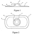
- the tire patch 1 is composed of a vulcanized rubber compound and comprises three major components: a base 3 for attachment to the inner liner of a tire, a platform 7 for supporting variously selected electronic components, and a pillar 5 for coupling the base 3 to the platform 7 and providing at least partial isolation or decoupling of any electronic devices which may be mounted on the platform 7 from road and tire induced conditions that may adversely effect electronic devices supported by tire patch 1.
- a base 3 for attachment to the inner liner of a tire
- a platform 7 for supporting variously selected electronic components
- a pillar 5 for coupling the base 3 to the platform 7 and providing at least partial isolation or decoupling of any electronic devices which may be mounted on the platform 7 from road and tire induced conditions that may adversely effect electronic devices supported by tire patch 1.
- Edges 9 of the base 3 may be feathered to avoid stress concentration around the perimeter of the base.
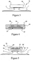
- the generally oval shape of the base 3, as best seen in Fig. 2 also assists in avoiding stress concentration.
- the base 3 is relatively thin to allow for bending of the base portion as the tire in which the tire patch 1 may be mounted flattens when it comes in contact with the ground or road surface.
- a tapered profile 11 is provided for the transition area from the base 3 of the tire patch 1 to the pillar 5 so as to uniformly distribute any stress propagating between any electronic device that may be mounted on the platform 7 and the tire inner liner to which the base 3 may be attached.
- the pillar 5 is necked down, as best seen in Fig. 1 , to an optimum width to support any electronic device that may be mounted on the platform 7.
- the edges 13 of the platform are flared to avoid stress concentration at the edge of the platform 7 in a manner similar to the feathering of the edges 9 of the base portion of the tire patch 1.
- the platform 7 per se is provided with a generally flat, circular shape (as seen in Figs. 1 and 2 ) so as to provide a flat surface for bonding to an electronic module which may be positioned on top of the platform 7 and a circular shape so as to provide optimum strength in all directions.
- the tire patch 1 is designed to take the maximum force (centrifugal and inertial) generated by any electronic device which may be secured to the platform 7 and distribute the force to a sufficient area of a tire inner liner so as to prevent any damage to the tire and to assure good adhesion of the tire patch 1 to a tire inner liner using available rubber-to-rubber bonding techniques.
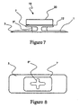
- FIG. 3 there is illustrated an encapsulated tag assembly 20, as will presently be more fully described, secured to the mounting platform 7 of tire patch 1.
- tag assembly 20 secured to the mounting platform 7 of tire patch 1.
- Such integrated combination of tag assembly 20 and tire patch 1 yields an exemplary patch assembly 16.
- Tag assembly 20 consists of an electronic device 21 that may be composed of a circuit board 22 on which a plurality of circuit elements 24, 26 may be mounted.
- the electronic device monitors the tire by collecting, storing and/or reading at least one engineering condition of the tire.
- circuit elements 24, 26 are intended to representatively illustrate any number (i.e., more or less that the two representatively illustrated components) of a large variety of electrical components, which components may include sensors of various types and other electronic components including, but not limited to, microprocessors, memory elements, power supplies including one or more batteries, transmitter and receiver devices, antenna elements and other similar components.
- Sensors may include, but ate not limited to, elements and devices for sensing temperature, pressure, tire rotation, and other engineering conditions of the tire in which the tag assembly is mounted
- the tag assembly may be designed to monitor the tire in which it is mounted by collecting and storing for later retrieval, any type of tire related engineering data desired and/or other types of tire related data as, for example, manufacturing data including serial number, manufacturing time, date and location, or any other type of relevant data desired to be associated with the particular tire.
- the electronic device 21 may be encapsulated by placing the completed device in a half mould and then filling the half mould with potting material such that the potting material fills the mould and flows around the electronic device 21. ter the potting material has dried, the half mould may be removed to yield a rigid tag assembly 20 that may then be glued with an adhesive layer 12 directly to the platform 7 of tire patch 1 as illustrated in Fig. 3 .
- a rigid housing 30 may be provided fitting with the contour of the electronic device 21.
- the rigid housing 30 takes the form of a rigid half shell made up of a closed bottom or lower portion 36, side walls 34, 34' and an open upper portion 32. It will be appreciated that, although only two side walls are designated in Fig. 5 , there are, in fact, four such walls completing the structure.
- the electronic device 21 may then be potted into the rigid housing 30 by filling the rigid housing 30 with a potting material 28 that fills the rigid housing 30 and flows around the electronic device 21.
- a rigid tag assembly having at least one side made of potting material and other sides a rigid housing is produced which may then be secured to the tire patch 1 by bonding one side of the rigid housing 30 to the platform 7 of the tire patch 1 using an adhesive layer 12.
- the sequence of assembling the electronic device 21 to the platform 7 of the tire patch 1 may be performed either before or after the tire patch 1 is attached to the inner liner of a tire.
- the rigid housing 30 may first be affixed to the platform 7 by way of adhesive layer 12 followed by encapsulation of the electronic device 21 into the rigid housing 30 by potting material 28.
- FIG. 6 Yet another alternative technique for securing the electronic device 21 to the platform 7 of a tire patch 1 is illustrated in Fig. 6 .
- the printed circuit board 22 of the electronic device 21 has an upper side fitted with representatively illustrated electronic components 24, 26 and a bottom side.
- the bottom side of the circuit board 22 is directly bonded to the platform 7 of the tire patch 1 by applying a suitable adhesive 12 between the bottom side of circuit board 22 and the flat rubber platform 7.
- the circuit board 22 may then be pressed onto the flat rubber platform 7.
- the bonded electronic device 21 is covered with a varnish or conformal coating material 28' that may be composed of a composition similar to the encapsulating or potting material 28 previously described.
- a varnish or conformal coating material 28' may be composed of a composition similar to the encapsulating or potting material 28 previously described.
- the coating material 28' is arranged to not only completely cover the electronic device 21 including the circuit board 22 and all components 24, 26, but also to cover at least a portion of the flared edges 13 of the platform 7.
- the resultant patch assembly 16' of Fig. 6 may then be secured to the inner liner of a tire using any suitable technique. As with the arrangement illustrated in Fig. 5 , the sequence of assembling the electronic device 21 to the platform 7 of the tire patch 1 may be performed either before or after the tire patch 1 is attached to the inner liner of a tire.
- a patch assembly embodiment 19 according to the invention is illustrated in Figs. 7 and 8 .
- the tire patch 1 illustrated in Figs. 7 and 8 retains all of the features previously illustrated except for the pillar.
- the pillar 5" has an outer contour shaped like a cross. It has been found that this cross-shaped contour provides a higher level of rejection of some frequency modes, thus providing improved decoupling of any electronic device 20 which may be affixed to the platform 7 from stress and vibration transmitted to the electronic device 20 from the tire as it comes into contact with a traveled surface.
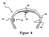
- a patch assembly 16 is mounted within a pneumatic tire 40.
- reference numeral 16 is used here to represent the exemplary patch assembly integrated with pneumatic tire 40, it should be appreciated that any specific patch assembly, including exemplary embodiments 16, 16', and 19, may be utilized.
- tire 40 includes an inner liner 42.
- the patch assembly 16 disclosed herein may be mounted at various locations within the pneumatic tire; two of these locations are illustrated at the crown portion 45 of the tire and near the sidewall portion 47.
- the patch assembly 16 may be mounted at any convenient location on the inner liner of the tire, the two locations shown merely being exemplary of such possible mounting locations.
- the tag assembly 20 illustratively attached to the tire patch 1 in Fig. 7 might be replaced by the rigid housing 30 configuration illustrated in Fig. 5 or the directly bonded and encapsulated electronic device 21 as illustrated in Fig. 6 .
Landscapes
- Engineering & Computer Science (AREA)
- Mechanical Engineering (AREA)
- Tires In General (AREA)
- Arrangements For Transmission Of Measured Signals (AREA)
Applications Claiming Priority (2)
| Application Number | Priority Date | Filing Date | Title |
|---|---|---|---|
| US737642 | 2003-12-16 | ||
| US10/737,642 US20050126668A1 (en) | 2003-12-16 | 2003-12-16 | Post patch for mounting devices inside tires |
Publications (3)
| Publication Number | Publication Date |
|---|---|
| EP1544001A1 EP1544001A1 (en) | 2005-06-22 |
| EP1544001A9 EP1544001A9 (en) | 2007-05-16 |
| EP1544001B1 true EP1544001B1 (en) | 2009-01-14 |
Family
ID=34523154
Family Applications (1)
| Application Number | Title | Priority Date | Filing Date |
|---|---|---|---|
| EP04106046A Expired - Lifetime EP1544001B1 (en) | 2003-12-16 | 2004-11-24 | Post patch for mounting devices inside tires |
Country Status (6)
| Country | Link |
|---|---|
| US (1) | US20050126668A1 (https=) |
| EP (1) | EP1544001B1 (https=) |
| JP (1) | JP4756857B2 (https=) |
| CN (1) | CN100453347C (https=) |
| BR (1) | BRPI0405509A (https=) |
| DE (1) | DE602004019037D1 (https=) |
Families Citing this family (37)
| Publication number | Priority date | Publication date | Assignee | Title |
|---|---|---|---|---|
| US7196617B2 (en) * | 2004-04-19 | 2007-03-27 | Michelin Recherche Et Technique S.A. | Graduated stiffness for electrical connections in tires |
| JP4516790B2 (ja) * | 2004-07-07 | 2010-08-04 | 株式会社ブリヂストン | タイヤ内電子デバイス取付台座 |
| JP4732788B2 (ja) * | 2005-04-26 | 2011-07-27 | 株式会社ブリヂストン | 保護部材、電子式モニター装置及び空気入りタイヤ |
| JP4901148B2 (ja) * | 2005-07-15 | 2012-03-21 | 株式会社ブリヂストン | 電子部品取付用台座及び台座付タイヤ |
| JP4778786B2 (ja) * | 2005-12-12 | 2011-09-21 | 株式会社ブリヂストン | 電子装置取付構造、及び空気入りタイヤ |
| US7770444B2 (en) * | 2005-12-13 | 2010-08-10 | Michelin Recherche Et Technique S.A. | Patch for fixing an electronic system to a tire |
| FR2894519B1 (fr) * | 2005-12-13 | 2010-02-12 | Michelin Soc Tech | Emplatre pour fixer un systeme electronique sur un pneumatique |
| JP4980621B2 (ja) * | 2006-01-06 | 2012-07-18 | 株式会社ブリヂストン | 取付パッチ構造及び空気入りタイヤ |
| US8261798B2 (en) * | 2006-10-30 | 2012-09-11 | Michelin Recherche Et Technique S.A. | Polyurethaneurea system |
| WO2008147409A1 (en) * | 2007-05-25 | 2008-12-04 | Societe De Technologie Michelin | Method to protect tire electronics |
| FR2922486B1 (fr) * | 2007-10-23 | 2009-12-11 | Michelin Soc Tech | Ensemble d'un pneumatique et d'un organe souple |
| FR2922488B1 (fr) * | 2007-10-23 | 2009-12-11 | Michelin Soc Tech | Organe formant support pour un dispositif et pneumatique comportant un tel organe |
| FR2922487B1 (fr) * | 2007-10-23 | 2009-12-11 | Michelin Soc Tech | Organe formant support pour un dispositif et pneumatique comprenant un tel organe |
| JP5117935B2 (ja) * | 2008-06-13 | 2013-01-16 | 株式会社ブリヂストン | パッチ設計方法 |
| GB2463870A (en) * | 2008-09-24 | 2010-03-31 | Transense Technologies Plc | Tyre sensor mounting assembly |
| FR2936184B1 (fr) * | 2008-09-24 | 2010-10-15 | Michelin Soc Tech | Organe de support a courbure continue. |
| FR2940166B1 (fr) * | 2008-12-24 | 2011-02-11 | Michelin Soc Tech | Procede de fabrication d'un element de garniture et d'un element de soutien destines a un moule de pneumatique |
| US8430142B2 (en) | 2009-02-25 | 2013-04-30 | The Goodyear Tire & Rubber Company | Environmentally resistant assembly containing an electronic device for use in a tire |
| US20120091209A1 (en) * | 2009-06-29 | 2012-04-19 | Elizabeth Hotaling | Flexible middle layer for rfid patch on tires |
| CN102371859B (zh) * | 2010-08-19 | 2014-02-12 | 青岛泰凯英轮胎有限公司 | 轮胎胎压监测系统安装底座及装置 |
| US8596117B2 (en) | 2011-10-03 | 2013-12-03 | Bridgestone Americas Tire Operations, Llc | Attachment patch for mounting various devices |
| JP5837851B2 (ja) * | 2012-04-24 | 2015-12-24 | 株式会社ブリヂストン | 空気入りタイヤ内面への電子部品取付構造 |
| DE202013011157U1 (de) | 2013-12-17 | 2014-02-19 | Continental Teves Ag & Co. Ohg | Sensor mit integrierter Identifikationseinrichtung |
| FR3029845B1 (fr) * | 2014-12-15 | 2017-08-11 | Michelin & Cie | Patch pour module electronique de pneumatique |
| WO2016099633A1 (en) | 2014-12-19 | 2016-06-23 | Bridgestone Americas Tire Operations, Llc | Attachment patch for mounting devices |
| US10639948B2 (en) | 2014-12-30 | 2020-05-05 | Bridgestone Americas Tire Operations, Llc | Assembly for attaching an electronics package to a tire |
| KR101781698B1 (ko) * | 2015-11-13 | 2017-09-25 | 한국타이어 주식회사 | 센서패치를 구비하는 타이어 센서설치구조 및 이의 제조방법 |
| JP6617666B2 (ja) * | 2016-09-07 | 2019-12-11 | 株式会社デンソー | タイヤマウントセンサ |
| US11051087B2 (en) * | 2017-11-08 | 2021-06-29 | Compagnie Generale Des Etablissements Michelin | Electronic assembly with a patch for a tire |
| JP7004559B2 (ja) * | 2017-12-08 | 2022-02-10 | Toyo Tire株式会社 | タイヤへの電子部品の固定構造、及び空気入りタイヤ |
| EP3727899B1 (en) * | 2017-12-18 | 2024-01-31 | Pirelli Tyre S.P.A. | Tyre monitoring device comprising an electronic unit and tyre comprising said device |
| US10621485B2 (en) * | 2018-02-28 | 2020-04-14 | FineLine Technologies | RFID mesh label, tire having RFID mesh label integrally incorporated therein, and methods of making |
| JP7162486B2 (ja) * | 2018-10-01 | 2022-10-28 | 株式会社ブリヂストン | 機能部品、機能部品のタイヤへの取り付け構造及びタイヤ |
| JP7241230B2 (ja) * | 2019-08-05 | 2023-03-16 | ブリヂストン アメリカズ タイヤ オペレーションズ、 エルエルシー | タイヤ電子機器アセンブリ |
| GB2599613B (en) * | 2020-04-29 | 2022-09-28 | Tpms Tape Ltd | Internal sensor fixing |
| JP7672622B2 (ja) * | 2021-02-25 | 2025-05-08 | 住友ゴム工業株式会社 | タイヤ |
| CN116917145A (zh) * | 2021-02-25 | 2023-10-20 | 住友橡胶工业株式会社 | 轮胎 |
Family Cites Families (19)
| Publication number | Priority date | Publication date | Assignee | Title |
|---|---|---|---|---|
| US174925A (en) * | 1876-03-21 | Improvement in toe-weights for trotting-horses | ||
| US124934A (en) * | 1872-03-26 | Improvement in traveling-bag clasps | ||
| US6087930A (en) * | 1994-02-22 | 2000-07-11 | Computer Methods Corporation | Active integrated circuit transponder and sensor apparatus for transmitting vehicle tire parameter data |
| US5731754A (en) * | 1994-06-03 | 1998-03-24 | Computer Methods Corporation | Transponder and sensor apparatus for sensing and transmitting vehicle tire parameter data |
| GB9619181D0 (en) * | 1996-09-13 | 1996-10-23 | Sumitomo Rubber Ind | Sensor for a pneumatic tyre |
| US5971046A (en) * | 1997-09-17 | 1999-10-26 | Bridgestone/Firestone, Inc. | Method and apparatus for bonding an active tag to a patch and a tire |
| US7009506B2 (en) * | 1998-02-10 | 2006-03-07 | Bridgestone Firestone North American Tire, Llc | Electronic monitoring device and patch assembly |
| US6030478A (en) * | 1998-02-10 | 2000-02-29 | Bridgestone/Firestone, Inc. | Method and apparatus for removably inserting an electric tire tag into a tire |
| US6309494B1 (en) * | 1998-12-04 | 2001-10-30 | Bridgestone/Firestone Research, Inc. | Method of attaching sensitive electronic equipment to the inner surface of a tire |
| US6192746B1 (en) * | 1999-04-29 | 2001-02-27 | Bridgestone/Firestone Research, Inc. | Apparatus and method of providing electrical power to an active electronic device embedded within a tire |
| US6388567B1 (en) * | 1999-04-29 | 2002-05-14 | Bridgestone/Firestone North American Tire, Llc | Combination monitoring device and patch for a pneumatic tire and method of installing the same |
| US6255940B1 (en) * | 1999-10-01 | 2001-07-03 | The Goodyear Tire & Rubber Company | Apparatus for monitoring a condition of a tire |
| US6462650B1 (en) * | 2000-08-11 | 2002-10-08 | Raymond J. Balzer | Tire module attachment mount |
| US7331367B2 (en) * | 2000-03-31 | 2008-02-19 | Bridgestone Firestone North American Tire, Llc | Monitoring device and patch assembly |
| US7161476B2 (en) * | 2000-07-26 | 2007-01-09 | Bridgestone Firestone North American Tire, Llc | Electronic tire management system |
| DE10243441B4 (de) * | 2002-09-18 | 2004-12-30 | Continental Aktiengesellschaft | Transponder für Reifen |
| DE10255138A1 (de) * | 2002-11-26 | 2004-06-17 | Iq-Mobil Electronics Gmbh | Haltevorrichtung zur Befestigung eines elektronischen Bauteils |
| US6854324B2 (en) * | 2002-12-20 | 2005-02-15 | The Goodyear Tire & Rubber Company | Tire monitoring apparatus |
| US20050076982A1 (en) * | 2003-10-09 | 2005-04-14 | Metcalf Arthur Richard | Post patch assembly for mounting devices in a tire interior |
-
2003
- 2003-12-16 US US10/737,642 patent/US20050126668A1/en not_active Abandoned
-
2004
- 2004-11-24 EP EP04106046A patent/EP1544001B1/en not_active Expired - Lifetime
- 2004-11-24 DE DE602004019037T patent/DE602004019037D1/de not_active Expired - Lifetime
- 2004-12-13 BR BR0405509-8A patent/BRPI0405509A/pt not_active IP Right Cessation
- 2004-12-15 CN CNB2004101012163A patent/CN100453347C/zh not_active Expired - Fee Related
- 2004-12-16 JP JP2004364489A patent/JP4756857B2/ja not_active Expired - Fee Related
Also Published As
| Publication number | Publication date |
|---|---|
| DE602004019037D1 (de) | 2009-03-05 |
| JP2005178761A (ja) | 2005-07-07 |
| JP4756857B2 (ja) | 2011-08-24 |
| CN100453347C (zh) | 2009-01-21 |
| CN1636773A (zh) | 2005-07-13 |
| BRPI0405509A (pt) | 2005-09-20 |
| US20050126668A1 (en) | 2005-06-16 |
| EP1544001A1 (en) | 2005-06-22 |
| EP1544001A9 (en) | 2007-05-16 |
Similar Documents
| Publication | Publication Date | Title |
|---|---|---|
| EP1544001B1 (en) | Post patch for mounting devices inside tires | |
| US7186308B2 (en) | System and method for providing tire electronics mounting patches | |
| US20050076982A1 (en) | Post patch assembly for mounting devices in a tire interior | |
| US9242516B2 (en) | Power component and instrumented tyre | |
| EP1501691B1 (en) | Monitoring device and patch assembly | |
| KR100672544B1 (ko) | 공기 타이어를 위한 모니터링 장치와 패치의 결합체, 및안테나가 결합된 이 결합체를 설치하는 방법 | |
| KR100672614B1 (ko) | 공기 타이어용 모니터링 장치와 패치의 결합체 및 그것의장착법 | |
| EP2182576B1 (en) | Tire and tag assembly | |
| EP1078780A2 (en) | Method and apparatus for removably inserting an electronic tire tag into a tire | |
| CA2247556A1 (en) | Method and apparatus for bonding an active tag to a patch and a tire | |
| EP1889025B1 (en) | Use of piezoelectric sensor attached to electronics package housing | |
| US20030089451A1 (en) | Attachment patch for mounting an electronic monitoring device to the inside of a pneumatic tire | |
| KR20080033034A (ko) | 타이어 압력 모니터링 센서 | |
| AU2018290186B2 (en) | Tire health sensor assembly | |
| JP2000351308A (ja) | タイヤタグ用ダイポールアンテナ | |
| JP2004523425A (ja) | 電子モニタリングモジュールをタイヤに固定する固定具 | |
| EP2217457A1 (en) | Wheel-monitoring module | |
| US20210016614A1 (en) | Tire with an integrated rfid and tpms sensor | |
| CN106660418A (zh) | 具有双组分外壳的轮胎压力监测单元 | |
| US20070028699A1 (en) | Pressure sensor | |
| CN113165452B (zh) | 包括监测装置的轮胎 |
Legal Events
| Date | Code | Title | Description |
|---|---|---|---|
| PUAI | Public reference made under article 153(3) epc to a published international application that has entered the european phase |
Free format text: ORIGINAL CODE: 0009012 |
|
| AK | Designated contracting states |
Kind code of ref document: A1 Designated state(s): AT BE BG CH CY CZ DE DK EE ES FI FR GB GR HU IE IS IT LI LU MC NL PL PT RO SE SI SK TR |
|
| AX | Request for extension of the european patent |
Extension state: AL HR LT LV MK YU |
|
| 17P | Request for examination filed |
Effective date: 20050721 |
|
| AKX | Designation fees paid |
Designated state(s): DE FR GB IT |
|
| 17Q | First examination report despatched |
Effective date: 20061123 |
|
| GRAP | Despatch of communication of intention to grant a patent |
Free format text: ORIGINAL CODE: EPIDOSNIGR1 |
|
| GRAS | Grant fee paid |
Free format text: ORIGINAL CODE: EPIDOSNIGR3 |
|
| GRAA | (expected) grant |
Free format text: ORIGINAL CODE: 0009210 |
|
| AK | Designated contracting states |
Kind code of ref document: B1 Designated state(s): DE FR GB IT |
|
| REG | Reference to a national code |
Ref country code: GB Ref legal event code: FG4D |
|
| REF | Corresponds to: |
Ref document number: 602004019037 Country of ref document: DE Date of ref document: 20090305 Kind code of ref document: P |
|
| PLBE | No opposition filed within time limit |
Free format text: ORIGINAL CODE: 0009261 |
|
| STAA | Information on the status of an ep patent application or granted ep patent |
Free format text: STATUS: NO OPPOSITION FILED WITHIN TIME LIMIT |
|
| 26N | No opposition filed |
Effective date: 20091015 |
|
| REG | Reference to a national code |
Ref country code: FR Ref legal event code: PLFP Year of fee payment: 12 |
|
| PGFP | Annual fee paid to national office [announced via postgrant information from national office to epo] |
Ref country code: GB Payment date: 20151118 Year of fee payment: 12 |
|
| REG | Reference to a national code |
Ref country code: FR Ref legal event code: PLFP Year of fee payment: 13 |
|
| GBPC | Gb: european patent ceased through non-payment of renewal fee |
Effective date: 20161124 |
|
| REG | Reference to a national code |
Ref country code: FR Ref legal event code: PLFP Year of fee payment: 14 |
|
| PG25 | Lapsed in a contracting state [announced via postgrant information from national office to epo] |
Ref country code: GB Free format text: LAPSE BECAUSE OF NON-PAYMENT OF DUE FEES Effective date: 20161124 |
|
| PGFP | Annual fee paid to national office [announced via postgrant information from national office to epo] |
Ref country code: DE Payment date: 20191121 Year of fee payment: 16 |
|
| PGFP | Annual fee paid to national office [announced via postgrant information from national office to epo] |
Ref country code: FR Payment date: 20191120 Year of fee payment: 16 |
|
| REG | Reference to a national code |
Ref country code: DE Ref legal event code: R119 Ref document number: 602004019037 Country of ref document: DE |
|
| PG25 | Lapsed in a contracting state [announced via postgrant information from national office to epo] |
Ref country code: FR Free format text: LAPSE BECAUSE OF NON-PAYMENT OF DUE FEES Effective date: 20201130 |
|
| PG25 | Lapsed in a contracting state [announced via postgrant information from national office to epo] |
Ref country code: DE Free format text: LAPSE BECAUSE OF NON-PAYMENT OF DUE FEES Effective date: 20210601 |
|
| PGFP | Annual fee paid to national office [announced via postgrant information from national office to epo] |
Ref country code: IT Payment date: 20211119 Year of fee payment: 18 |
|
| PG25 | Lapsed in a contracting state [announced via postgrant information from national office to epo] |
Ref country code: IT Free format text: LAPSE BECAUSE OF NON-PAYMENT OF DUE FEES Effective date: 20221124 |