EP1543272B1 - Brennstoffdüse für eine gasturbine - Google Patents
Brennstoffdüse für eine gasturbine Download PDFInfo
- Publication number
- EP1543272B1 EP1543272B1 EP03741799A EP03741799A EP1543272B1 EP 1543272 B1 EP1543272 B1 EP 1543272B1 EP 03741799 A EP03741799 A EP 03741799A EP 03741799 A EP03741799 A EP 03741799A EP 1543272 B1 EP1543272 B1 EP 1543272B1
- Authority
- EP
- European Patent Office
- Prior art keywords
- fuel
- nozzle
- radially
- delivery member
- flow conditioning
- Prior art date
- Legal status (The legal status is an assumption and is not a legal conclusion. Google has not performed a legal analysis and makes no representation as to the accuracy of the status listed.)
- Expired - Lifetime
Links
Images
Classifications
-
- F—MECHANICAL ENGINEERING; LIGHTING; HEATING; WEAPONS; BLASTING
- F23—COMBUSTION APPARATUS; COMBUSTION PROCESSES
- F23R—GENERATING COMBUSTION PRODUCTS OF HIGH PRESSURE OR HIGH VELOCITY, e.g. GAS-TURBINE COMBUSTION CHAMBERS
- F23R3/00—Continuous combustion chambers using liquid or gaseous fuel
- F23R3/28—Continuous combustion chambers using liquid or gaseous fuel characterised by the fuel supply
- F23R3/286—Continuous combustion chambers using liquid or gaseous fuel characterised by the fuel supply having fuel-air premixing devices
-
- F—MECHANICAL ENGINEERING; LIGHTING; HEATING; WEAPONS; BLASTING
- F23—COMBUSTION APPARATUS; COMBUSTION PROCESSES
- F23R—GENERATING COMBUSTION PRODUCTS OF HIGH PRESSURE OR HIGH VELOCITY, e.g. GAS-TURBINE COMBUSTION CHAMBERS
- F23R3/00—Continuous combustion chambers using liquid or gaseous fuel
- F23R3/02—Continuous combustion chambers using liquid or gaseous fuel characterised by the air-flow or gas-flow configuration
- F23R3/04—Air inlet arrangements
- F23R3/10—Air inlet arrangements for primary air
- F23R3/12—Air inlet arrangements for primary air inducing a vortex
- F23R3/14—Air inlet arrangements for primary air inducing a vortex by using swirl vanes
-
- F—MECHANICAL ENGINEERING; LIGHTING; HEATING; WEAPONS; BLASTING
- F23—COMBUSTION APPARATUS; COMBUSTION PROCESSES
- F23C—METHODS OR APPARATUS FOR COMBUSTION USING FLUID FUEL OR SOLID FUEL SUSPENDED IN A CARRIER GAS OR AIR
- F23C2900/00—Special features of, or arrangements for combustion apparatus using fluid fuels or solid fuels suspended in air; Combustion processes therefor
- F23C2900/07001—Air swirling vanes incorporating fuel injectors
-
- F—MECHANICAL ENGINEERING; LIGHTING; HEATING; WEAPONS; BLASTING
- F23—COMBUSTION APPARATUS; COMBUSTION PROCESSES
- F23D—BURNERS
- F23D2900/00—Special features of, or arrangements for burners using fluid fuels or solid fuels suspended in a carrier gas
- F23D2900/14—Special features of gas burners
- F23D2900/14004—Special features of gas burners with radially extending gas distribution spokes
Definitions
- This invention relates generally to the field of fuel nozzles and, more particularly, to a combustor and associated fuel nozzle having improved fuel concentration profile characteristics.
- Combustion engines are machines that convert chemical energy stored in fuel into mechanical energy useful for generating electricity, producing thrust, or otherwise doing work. These engines typically include several cooperative sections that contribute in some way to this energy conversion process.
- gas turbine engines air discharged from a compressor section and fuel introduced from a fuel supply are mixed together and burned in a combustion section. The products of combustion are harnessed and directed through a turbine section, where they expand and turn a central rotor.
- One popular combustor design includes a centralized pilot nozzle and several main fuel injector nozzles arranged circumferentially around the pilot nozzle. With this design, the nozzles are arranged to form a pilot flame zone and a mixing region.
- the pilot nozzle selectively produces a stable flame which is anchored in the pilot flame zone, while the main nozzles produce a mixed stream of fuel and air in the above-referenced mixing region. The stream of mixed fuel and air flows out of the mixing region, past the pilot flame zone, and into a main combustion zone, where additional combustion occurs. Energy released during combustion is captured by the downstream components to produce electricity or otherwise do work.
- high-swirl-combustion occurs in the pilot flame zone, with low-swirl-number combustion occurring in the main combustion zone.
- high-swirl-number combustion is characterized by relatively-compact flames, with high rates of rotation and relatively-low rates of longitudinal propagation.
- Low-swirl-number combustion conversely, is characterized by flames which are relatively more spread out.
- this type of combustor is also resistant to thermo-acoustic excitations.
- These combustors also present a relatively-long pre-combustion mixing path for the fuel and air which helps ensure even-temperature burning and reduced emissions levels. Accordingly, this type of combustor is a popular choice for use in industrial turbine engines.
- the internal fuel-and-air streams are well-mixed, to avoid localized, fuel-rich regions. Combustion of over-rich pockets of fuel and air leads to high-temperature combustion that produces high levels of unwanted NOx emissions. As a result, efforts have been made to produce combustors with essentially-uniform distributions of fuel and air. Swirler elements, for example, are often used to produce a stream of fuel and air in which air and injected fuel are evenly mixed.
- a performance-enhancing nozzle suitable for use in combustors which combine high-swirl-number combustion in a pilot zone with low-swirl-number combustion in a main combustion zone.
- the nozzle should eliminate combustion outside the mixing zone immediately downstream of the nozzle, without negatively impacting the overall performance of the combustor.
- the nozzle should produce a radially-biased fuel concentration profile which reduces the tendency for flame holding at the nozzle tip.
- the nozzle should also provide the desired fuel concentration profile over a wide range of operating conditions, without regard to fluctuating fuel and air inputs.
- the nozzle should be compatible with previously installed combustors, allowing the nozzle to be used in retrofit operations.
- EP-A-1 174 662 discloses a combustor which can simultaneously reduce an amount of NOx exhaust and combustion oscillation.
- the combustor comprises an internal cylinder which accommodates a premixing nozzle, and an external cylinder which accommodates the internal cylinder and includes an air flow passage which supplies air from a compressor to the premixing nozzle.
- the air flow passage is provided with a punched metal plate near the maximum velocity fluctuation position wherein the velocity fluctuation of the air flow is increased to the maximum.
- the instant invention is a performance-enhancing nozzle suitable for use in combustors which combine high-swirl-number combustion in a pilot zone with low-swirl-number combustion in a main combustion zone.
- a nozzle for a combustor comprising:
- the fuel exit ports may be high-momentum, having a design pressure ratio greater than 1.1.
- the nozzle may be part of a combustor which produces high-swirl-number combustion in a pilot zone and low-swirl-number combustion in a main combustion zone.
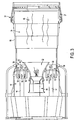
- the nozzle 10 of the present invention includes a centralized fuel delivery member 14 which is in fluid communication with a source of fuel (not shown).
- a source of fuel not shown.
- Several flow conditioning members 16 are disposed circumferentially around the fuel delivery member 14, and each of the flow conditioning members includes one or more fuel exit ports 18.
- the fuel exit ports 18 are, in turn, fluidly coupled with the fuel deliver member 14.
- Fuel 20 passes through the exit ports 18, and joins air 22 travelling over the flow conditioning members 16 to form a mixture 24 of fuel and air.
- the fuel exit ports 18 and flow conditioning members 16 ensure that the air and fuel mixture 24 has a concentration profile 26 that prevents the formation of flames at the downstream end 28 of the fuel delivery member 14.
- the nozzle 10 of the present invention will now be described in further detail.
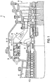
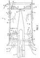
- the nozzle 10 of the present invention has features which make it especially well-suited for use as a main nozzle within a combustion system 30 that combines high-swirl-number combustion in a pilot flame zone 32 and low-swirl-number combustion in a main combustion zone 34.
- the nozzle 10 includes an elongated fuel delivery member 14 which resembles a tube characterized by a downstream tip 28.
- the fuel delivery member 14 is mounted within a nozzle sleeve 35, and the flow conditioning members 16 extend between the delivery member and the sleeve.
- the flow conditioning members 16 and fuel delivery member 14 may be formed as an integral unit; however, the flow conditioning members may be formed separately, if desired.
- a flashback annulus 37 which allows fluid communication between the inlet air 22 and the mixing region 36 is also included and helps lower flame-holding tendencies at the downstream end 39 of the nozzle sleeve 35.
- the flow conditioning members 16 are airfoil-shaped swirlers that extend radially outward from the fuel delivery member 14.
- the flow conditioning members 16 include preferably three fuel exit ports 18 positioned on each side so as to produce a radially-biased fuel concentration profile 26 in a mixing zone 36 located between the nozzle 10 and the main combustion zone 34. More particularly, the fuel exit ports 18 are located within a radially-outward portion 38 of the flow conditioning members 16; the radially-inward portion 40 of the flow conditioning members extending between the radially-outward portion and fuel delivery member contains no fuel exit ports.
- the distance D between the radially-innermost fuel exit port 18 and the fuel delivery member is within the range of about 30% to 40% of the passage height S R .
- the fuel exit ports 18 are spaced to produce a nearly even fuel distribution within the radially outward portion 38, but other suitable distributions such as biased toward the center of the passage may be employed as desired.
- the fuel exit ports 18 are spaced to produce a nearly-uniform fuel distribution within the radially-outward portion 38, but other suitable distributions such as biased toward the middle of the annulus (to enhance performance of the flashback annulus 37) may be employed as desired.
- the flow conditioning members 16 need not have an airfoil-shaped cross section, other suitable shapes which increase the turbulence, including static mixing elements may be used, as desired. It is also noted that not all flow conditioning members 16 need to include three fuel exit ports 18 on each side; more or fewer ports may be included, and some conditioning members may have no exit ports.
- the fuel exit ports 18 are sized and shaped to produce streams of fuel 20 having relatively-high momentum.
- the fuel exit ports 18 are characterized by a design pressure of about 1.2, with the preferred design pressure being between about 1.1 to about 1.4.
- the fuel exit ports 18 are generally formed normal to the surface of flow conditioning member 16, but this may be modified if desired, and the ports may have different or uniform diameters in order to achieve the required mixing profile within the circumferential variation over the operating range.
- the use of high-momentum jets is not required; however, injecting fuel in this manner provides enhanced stability of the fuel concentration profile 26, making the fuel distribution less sensitive to varying nozzle inlet conditions.
- the flow conditioning members 16 are swirlers shaped to impart low-swirl-number flow to fluids such as a mixture 24 of air 22 supplied by a compressor section 42, and fuel introduced by the fuel delivery member 14.
- the swirlers induce flow having a swirl number in the range between about 0.2 to about 0.6.
- swirl number refers to the known measurement term which quantifies the ratio between longitudinal momentum and rotational momentum for a given stream of fluid at the nozzle exit plane.
- the flow conditioning members contribute to fluid flow in the mixing zone and main combustion zones characterized by a swirl number of about 0.4.
- the nozzle 10 of the present invention acts as a main nozzle in a staged combustion system 30.
- main nozzles 10 are grouped together with a pilot nozzle 44 to combust a mixture 24 of fuel 20 and air 22.
- the products of this combustion provide a high-energy working fluid 46 that is transferred downstream to a turbine section 48 of an associated engine 12, where energy is extracted to do further work.
- a combustor liner 58 downstream of the main and pilot nozzles 10, 44 bounds the main combustion zone and interfaces with a transition section 60 to guide the products of combustion 46 into the turbine section 48.
- the pilot fuel nozzle 44 produces a stable flame within a pilot flame zone 32, which may be partially bounded by a boundary cone 50, as shown.
- fuel 20 and air 22 flow downstream from the main nozzles 10, they flow through a mixing region 36, where they form a mixture 24 having a radially-biased fuel concentration profile 26 (which is shown in Figure 2 ).
- the radially-outward portion 52 of the fuel-and-air mixture 24 flowing near the nozzle sleeve 35 is flammable, while the radially-inward portion 54 of the mixture is not flammable.
- the nozzle 10 of the present invention does not support combustion in the recirculation zone 56 located adjacent the nozzle downstream end or tip 28.
- the flammable, radially-outward portion 52 of the fuel-and-air mixture 24 occupies approximately the outer 75% of the radial spacing between the center of the passage and the outside of the passage.
- the fuel concentration profile 26 need not occupy the outer 75 percent, and may occupy an amount ranging from 60 to 90%. With this arrangement, the recirculation zone 56 remains essentially flame-free, while low-swirl-number combustion is supported in the main combustion zone 34.
- the fuel-and-air mixture 24 travels downstream until it contacts the pilot flame zone 32 which provides an anchoring flame and feeds continued combustion in the main combustion zone 34.
- the nozzle 10 of the present invention may be used in a new engine 12, or may be installed into an existing combustion system 30 during a retrofit operation.
Claims (5)
- Düse (10) für eine Brennkammer (30), welche umfasst:ein langgestrecktes Brennstoffzuführungselement (14), das für eine Fluidkommunikation mit einer Brennstoffquelle geeignet ist, wobei sich das besagte langgestreckte Brennstoffzuführungselement (14) entlang einer Achse erstreckt, wobei das besagte langgestreckte Brennstoffzuführungselement (14) von rohrförmiger Gestalt ist und ein stromabwärtiges Ende (28) aufweist;ein Strömungskonditionierungselement (16), das dem besagten Brennstoffzuführungselement (14) benachbart radial außerhalb des besagten Brennstoffzuführungselements (14) angeordnet ist, wobei das besagte Strömungskonditionierungselement (16) eine Brennstoffaustrittsöffnung (18) aufweist, die mit dem besagten Brennstoffzuführungselement (14) in Fluidkommunikation steht;wobei das besagte Strömungskonditionierungselement (16), das die besagte Brennstoffaustrittsöffnung (18) aufweist, dazu eingerichtet ist, ein Brennstoffkonzentrationsprofil (26) zu erzeugen, das die folgenden Bereiche (52, 54) in Bezug auf die besagte Achse, entlang der sich das besagte langgestreckte Brennstoffzuführungselement (14) erstreckt, aufweist: einen radial außen liegenden Bereich (52), welcher entflammbar ist, und einen radial innen liegenden Bereich (54), welcher nicht entflammbar ist,wodurch das besagte Brennstoffkonzentrationsprofil (26) bewirkt, dass sichergestellt wird, dass ein dem besagten stromabwärtigen Ende (28) des Brennstoffzuführungselements benachbarter Bereich (56) flammenfrei ist,wobei das besagte Strömungskonditionierungselement (16) sich von dem besagten Brennstoffzuführungselement (14) aus in radialer Richtung erstreckt,wobei das besagte Strömungskonditionierungselement (16) einen radial innen liegenden ersten Abschnitt (40) und einen radial außen liegenden zweiten Abschnitt (38) aufweist, wobei die besagte Brennstoffaustrittsöffnung (18) innerhalb des besagten radial außen liegenden zweiten Abschnitts (38) angeordnet ist,wobei das besagte Strömungskonditionierungselement (16) eine Vielzahl von Brennstoffaustrittsöffnungen (18) aufweist, die innerhalb des besagten radial außen liegenden zweiten Abschnitts (38) angeordnet sind,wobei der besagte radial außen liegende zweite Abschnitt (38) von dem besagten Brennstoffzuführungselement (14) in radialer Richtung einen Abstand (D) aufweist, der 30 % bis 40 % einer radialen Höhe (SR) des besagten Strömungskonditionierungselements (16) aufweist,dadurch gekennzeichnet, dass die besagte Düse (10) eine Rezirkulationszone (56) bildet, die dem besagten stromabwärtigen Ende (28) des Brennstoffzuführungselements benachbart ist, wobei das besagte Brennstoffkonzentrationsprofil (26) bewirkt, dass sichergestellt wird, dass die besagte Rezirkulationszone (56) nicht entflammbar ist, und das besagte Strömungskonditionierungselement (16) dazu eingerichtet ist, eine stromabwärts gerichtete Fluidströmung hervorzurufen, die eine Drallzahl aufweist, welche kleiner als 0,6 ist.
- Düse (10) nach Anspruch 1, wobei die besagte Brennstoffaustrittsöffnung (18) ein Auslegungsdruckverhältnis aufweist, welches bewirkt, dass Brennstoff mit einem Impuls eingeleitet wird, welcher bewirkt, dass sichergestellt wird, dass das besagte Brennstoffkonzentrationsprofil (26) im Wesentlichen konsistent bleibt, wenn vorgewählte Betriebsbedingungen variieren.
- Düse (10) nach Anspruch 2, wobei das besagte Auslegungsdruckverhältnis höher als 1,1 ist.
- Düse (10) nach Anspruch 3, wobei das besagte Auslegungsdruckverhältnis in einem Bereich von 1,1 bis 1,4 liegt.
- Brennkammer (30), welche umfasst:eine Brennstoffquelle;ein Auskleidungselement (58), das einen inneren Bereich (32, 34) definiert, wobei der besagte innere Bereich (32, 34) eine Pilotflammenzone (32) und eine Hauptverbrennungszone (34) umfasst;eine Pilotdüse (44), die einem ersten Ende des besagten Auskleidungselements (58) benachbart angeordnet ist, wobei die besagte Pilotdüse (44) mit der besagten Brennstoffquelle in Fluidkommunikation steht und dazu eingerichtet ist, der besagten Pilotflammenzone (32) eine Pilotflamme zur Verfügung zu stellen; undeine Hauptdüse (10), die ebenfalls dem besagten ersten Ende des besagten Auskleidungselements (58) benachbart angeordnet ist, wobei die besagte Hauptdüse (10) die Düse (10) von Anspruch 1 umfasst, wobei Brennstoff mit dem besagten Brennstoffkonzentrationsprofil (26), das von der besagten Hauptdüse (10) gewährleistet wird, in der besagten Hauptverbrennungszone (34) der besagten Brennkammer (30) verbrannt wird.
Applications Claiming Priority (3)
| Application Number | Priority Date | Filing Date | Title |
|---|---|---|---|
| US255892 | 1988-10-07 | ||
| US10/255,892 US6832481B2 (en) | 2002-09-26 | 2002-09-26 | Turbine engine fuel nozzle |
| PCT/US2003/014852 WO2004029515A1 (en) | 2002-09-26 | 2003-05-12 | Turbine engine fuel nozzle |
Publications (2)
| Publication Number | Publication Date |
|---|---|
| EP1543272A1 EP1543272A1 (de) | 2005-06-22 |
| EP1543272B1 true EP1543272B1 (de) | 2011-11-23 |
Family
ID=32041757
Family Applications (1)
| Application Number | Title | Priority Date | Filing Date |
|---|---|---|---|
| EP03741799A Expired - Lifetime EP1543272B1 (de) | 2002-09-26 | 2003-05-12 | Brennstoffdüse für eine gasturbine |
Country Status (5)
| Country | Link |
|---|---|
| US (1) | US6832481B2 (de) |
| EP (1) | EP1543272B1 (de) |
| JP (1) | JP4177812B2 (de) |
| KR (1) | KR100695269B1 (de) |
| WO (1) | WO2004029515A1 (de) |
Families Citing this family (44)
| Publication number | Priority date | Publication date | Assignee | Title |
|---|---|---|---|---|
| JP3986348B2 (ja) * | 2001-06-29 | 2007-10-03 | 三菱重工業株式会社 | ガスタービン燃焼器の燃料供給ノズルおよびガスタービン燃焼器並びにガスタービン |
| DE60228085D1 (de) * | 2002-09-20 | 2008-09-18 | Siemens Ag | Vormischbrenner mit profilierter Luftmassenströmung |
| WO2005085709A1 (ja) * | 2004-03-03 | 2005-09-15 | Mitsubishi Heavy Industries, Ltd. | 燃焼器 |
| WO2005095863A1 (de) * | 2004-03-31 | 2005-10-13 | Alstom Technology Ltd | Brenner |
| US7137258B2 (en) * | 2004-06-03 | 2006-11-21 | General Electric Company | Swirler configurations for combustor nozzles and related method |
| US7370466B2 (en) * | 2004-11-09 | 2008-05-13 | Siemens Power Generation, Inc. | Extended flashback annulus in a gas turbine combustor |
| US20060156734A1 (en) * | 2005-01-15 | 2006-07-20 | Siemens Westinghouse Power Corporation | Gas turbine combustor |
| US7513098B2 (en) * | 2005-06-29 | 2009-04-07 | Siemens Energy, Inc. | Swirler assembly and combinations of same in gas turbine engine combustors |
| US7703288B2 (en) * | 2005-09-30 | 2010-04-27 | Solar Turbines Inc. | Fuel nozzle having swirler-integrated radial fuel jet |
| US20070074518A1 (en) * | 2005-09-30 | 2007-04-05 | Solar Turbines Incorporated | Turbine engine having acoustically tuned fuel nozzle |
| US7490471B2 (en) * | 2005-12-08 | 2009-02-17 | General Electric Company | Swirler assembly |
| US8308477B2 (en) * | 2006-03-01 | 2012-11-13 | Honeywell International Inc. | Industrial burner |
| JP4719059B2 (ja) | 2006-04-14 | 2011-07-06 | 三菱重工業株式会社 | ガスタービンの予混合燃焼バーナー |
| US7721553B2 (en) * | 2006-07-18 | 2010-05-25 | Siemens Energy, Inc. | Method and apparatus for detecting a flashback condition in a gas turbine |
| KR100820233B1 (ko) | 2006-10-31 | 2008-04-08 | 한국전력공사 | 연소기 및 이를 포함하는 멀티 연소기, 그리고 연소방법 |
| US20080267783A1 (en) * | 2007-04-27 | 2008-10-30 | Gilbert Otto Kraemer | Methods and systems to facilitate operating within flame-holding margin |
| GB2455289B (en) * | 2007-12-03 | 2010-04-07 | Siemens Ag | Improvements in or relating to burners for a gas-turbine engine |
| US8291705B2 (en) * | 2008-08-13 | 2012-10-23 | General Electric Company | Ultra low injection angle fuel holes in a combustor fuel nozzle |
| US20100050649A1 (en) * | 2008-09-04 | 2010-03-04 | Allen David B | Combustor device and transition duct assembly |
| US20100058767A1 (en) * | 2008-09-05 | 2010-03-11 | General Electric Company | Swirl angle of secondary fuel nozzle for turbomachine combustor |
| US8490400B2 (en) * | 2008-09-15 | 2013-07-23 | Siemens Energy, Inc. | Combustor assembly comprising a combustor device, a transition duct and a flow conditioner |
| US8661779B2 (en) * | 2008-09-26 | 2014-03-04 | Siemens Energy, Inc. | Flex-fuel injector for gas turbines |
| US8104286B2 (en) * | 2009-01-07 | 2012-01-31 | General Electric Company | Methods and systems to enhance flame holding in a gas turbine engine |
| US8333075B2 (en) * | 2009-04-16 | 2012-12-18 | General Electric Company | Gas turbine premixer with internal cooling |
| EP2402652A1 (de) * | 2010-07-01 | 2012-01-04 | Siemens Aktiengesellschaft | Brenner |
| US8418469B2 (en) * | 2010-09-27 | 2013-04-16 | General Electric Company | Fuel nozzle assembly for gas turbine system |
| US8479521B2 (en) * | 2011-01-24 | 2013-07-09 | United Technologies Corporation | Gas turbine combustor with liner air admission holes associated with interspersed main and pilot swirler assemblies |
| US8365534B2 (en) | 2011-03-15 | 2013-02-05 | General Electric Company | Gas turbine combustor having a fuel nozzle for flame anchoring |
| RU2011115528A (ru) | 2011-04-21 | 2012-10-27 | Дженерал Электрик Компани (US) | Топливная форсунка, камера сгорания и способ работы камеры сгорания |
| US8955329B2 (en) | 2011-10-21 | 2015-02-17 | General Electric Company | Diffusion nozzles for low-oxygen fuel nozzle assembly and method |
| WO2013128572A1 (ja) * | 2012-02-28 | 2013-09-06 | 三菱重工業株式会社 | 燃焼器及びガスタービン |
| US9759425B2 (en) * | 2013-03-12 | 2017-09-12 | General Electric Company | System and method having multi-tube fuel nozzle with multiple fuel injectors |
| US9765973B2 (en) | 2013-03-12 | 2017-09-19 | General Electric Company | System and method for tube level air flow conditioning |
| US9651259B2 (en) | 2013-03-12 | 2017-05-16 | General Electric Company | Multi-injector micromixing system |
| US9528444B2 (en) | 2013-03-12 | 2016-12-27 | General Electric Company | System having multi-tube fuel nozzle with floating arrangement of mixing tubes |
| US9650959B2 (en) | 2013-03-12 | 2017-05-16 | General Electric Company | Fuel-air mixing system with mixing chambers of various lengths for gas turbine system |
| US9534787B2 (en) | 2013-03-12 | 2017-01-03 | General Electric Company | Micromixing cap assembly |
| US9671112B2 (en) | 2013-03-12 | 2017-06-06 | General Electric Company | Air diffuser for a head end of a combustor |
| KR101657535B1 (ko) * | 2015-05-21 | 2016-09-19 | 두산중공업 주식회사 | 버닝 저감 연료공급노즐. |
| WO2017034435A1 (en) * | 2015-08-26 | 2017-03-02 | General Electric Company | Systems and methods for a multi-fuel premixing nozzle with integral liquid injectors/evaporators |
| US20180363905A1 (en) * | 2016-01-13 | 2018-12-20 | General Electric Company | Fuel nozzle assembly for reducing multiple tone combustion dynamics |
| CN105650679A (zh) * | 2016-01-19 | 2016-06-08 | 西北工业大学 | 一种三级旋流部分预混的地面燃机燃烧室 |
| KR101792822B1 (ko) * | 2016-10-31 | 2017-11-01 | 한국기계연구원 | 팁 과열방지 구조를 가지는 연소기 노즐 및 이를 이용한 연소기 |
| KR102119879B1 (ko) | 2018-03-07 | 2020-06-08 | 두산중공업 주식회사 | 파일럿 연료 분사 장치, 이를 구비한 연료 노즐 및 가스 터빈 |
Family Cites Families (18)
| Publication number | Priority date | Publication date | Assignee | Title |
|---|---|---|---|---|
| US5317864A (en) * | 1992-09-30 | 1994-06-07 | Sundstrand Corporation | Tangentially directed air assisted fuel injection and small annular combustors for turbines |
| US5251447A (en) * | 1992-10-01 | 1993-10-12 | General Electric Company | Air fuel mixer for gas turbine combustor |
| US5407347A (en) * | 1993-07-16 | 1995-04-18 | Radian Corporation | Apparatus and method for reducing NOx, CO and hydrocarbon emissions when burning gaseous fuels |
| US5461865A (en) * | 1994-02-24 | 1995-10-31 | United Technologies Corporation | Tangential entry fuel nozzle |
| US5471840A (en) * | 1994-07-05 | 1995-12-05 | General Electric Company | Bluffbody flameholders for low emission gas turbine combustors |
| JPH09119641A (ja) * | 1995-06-05 | 1997-05-06 | Allison Engine Co Inc | ガスタービンエンジン用低窒素酸化物希薄予混合モジュール |
| US5813232A (en) * | 1995-06-05 | 1998-09-29 | Allison Engine Company, Inc. | Dry low emission combustor for gas turbine engines |
| JP3416357B2 (ja) | 1995-10-26 | 2003-06-16 | 三菱重工業株式会社 | 低NOxガスタービン燃焼器の予混合メインノズル |
| US5778676A (en) * | 1996-01-02 | 1998-07-14 | General Electric Company | Dual fuel mixer for gas turbine combustor |
| JP2858104B2 (ja) | 1996-02-05 | 1999-02-17 | 三菱重工業株式会社 | ガスタービン燃焼器 |
| JP3392633B2 (ja) | 1996-05-15 | 2003-03-31 | 三菱重工業株式会社 | 燃焼器 |
| JP3619626B2 (ja) * | 1996-11-29 | 2005-02-09 | 株式会社東芝 | ガスタービン燃焼器の運転方法 |
| JP3448190B2 (ja) | 1997-08-29 | 2003-09-16 | 三菱重工業株式会社 | ガスタービンの燃焼器 |
| JP4205231B2 (ja) * | 1998-02-10 | 2009-01-07 | ゼネラル・エレクトリック・カンパニイ | バーナ |
| US6038861A (en) | 1998-06-10 | 2000-03-21 | Siemens Westinghouse Power Corporation | Main stage fuel mixer with premixing transition for dry low Nox (DLN) combustors |
| US6179608B1 (en) * | 1999-05-28 | 2001-01-30 | Precision Combustion, Inc. | Swirling flashback arrestor |
| JP2002039533A (ja) | 2000-07-21 | 2002-02-06 | Mitsubishi Heavy Ind Ltd | 燃焼器、ガスタービン及びジェットエンジン |
| US6655145B2 (en) * | 2001-12-20 | 2003-12-02 | Solar Turbings Inc | Fuel nozzle for a gas turbine engine |
-
2002
- 2002-09-26 US US10/255,892 patent/US6832481B2/en not_active Expired - Lifetime
-
2003
- 2003-05-12 JP JP2004539780A patent/JP4177812B2/ja not_active Expired - Lifetime
- 2003-05-12 WO PCT/US2003/014852 patent/WO2004029515A1/en active Application Filing
- 2003-05-12 KR KR1020057005180A patent/KR100695269B1/ko active IP Right Grant
- 2003-05-12 EP EP03741799A patent/EP1543272B1/de not_active Expired - Lifetime
Also Published As
| Publication number | Publication date |
|---|---|
| US20040060297A1 (en) | 2004-04-01 |
| KR20050057579A (ko) | 2005-06-16 |
| US6832481B2 (en) | 2004-12-21 |
| WO2004029515A1 (en) | 2004-04-08 |
| EP1543272A1 (de) | 2005-06-22 |
| KR100695269B1 (ko) | 2007-03-14 |
| JP2006500544A (ja) | 2006-01-05 |
| JP4177812B2 (ja) | 2008-11-05 |
Similar Documents
| Publication | Publication Date | Title |
|---|---|---|
| EP1543272B1 (de) | Brennstoffdüse für eine gasturbine | |
| JP4846271B2 (ja) | インピンジメント冷却式センタボデーを備えた予混合バーナ及びセンタボデーの冷却方法 | |
| EP3320268B1 (de) | Brenner für eine gasturbine und verfahren zum betrieb des brenners | |
| CA2155374C (en) | Dual fuel mixer for gas turbine combuster | |
| US5899075A (en) | Turbine engine combustor with fuel-air mixer | |
| EP1426689B1 (de) | Gasturbinenbrennkammer mit Vormischbrennern, die eine verschiedene Geometrie aufweisen | |
| JP3970244B2 (ja) | 予混合ノズルおよび燃焼器並びにガスタービン | |
| EP2216600B1 (de) | Brennerdüse | |
| US8839628B2 (en) | Methods for operating a gas turbine engine apparatus and assembling same | |
| US6993916B2 (en) | Burner tube and method for mixing air and gas in a gas turbine engine | |
| US5351477A (en) | Dual fuel mixer for gas turbine combustor | |
| US8240150B2 (en) | Lean direct injection diffusion tip and related method | |
| US8499564B2 (en) | Pilot burner for gas turbine engine | |
| EP1371906B1 (de) | Gasturbinenbrennkammer mit Hohlraum für eingeschlossene Wirbel | |
| US6374615B1 (en) | Low cost, low emissions natural gas combustor | |
| US20090056336A1 (en) | Gas turbine premixer with radially staged flow passages and method for mixing air and gas in a gas turbine | |
| US20100077759A1 (en) | Tubular Fuel Injector for Secondary Fuel Nozzle | |
| US7836677B2 (en) | At least one combustion apparatus and duct structure for a gas turbine engine | |
| US20100319353A1 (en) | Multiple Fuel Circuits for Syngas/NG DLN in a Premixed Nozzle | |
| US10125992B2 (en) | Gas turbine combustor with annular flow sleeves for dividing airflow upstream of premixing passages | |
| AU2007203536A1 (en) | Liquid fuel enhancement for natural gas swirl stabilized nozzle and method | |
| WO2020259919A1 (en) | Combustor for a gas turbine | |
| CN107525095A (zh) | 一种燃气轮机轴向分级单管燃烧室 | |
| JP3192055B2 (ja) | ガスタービン燃焼器 | |
| US20110107767A1 (en) | Secondary fuel nozzle venturi |
Legal Events
| Date | Code | Title | Description |
|---|---|---|---|
| PUAI | Public reference made under article 153(3) epc to a published international application that has entered the european phase |
Free format text: ORIGINAL CODE: 0009012 |
|
| 17P | Request for examination filed |
Effective date: 20050207 |
|
| AK | Designated contracting states |
Kind code of ref document: A1 Designated state(s): AT BE BG CH CY CZ DE DK EE ES FI FR GB GR HU IE IT LI LU MC NL PT RO SE SI SK TR |
|
| RBV | Designated contracting states (corrected) |
Designated state(s): DE FR GB IT |
|
| 17Q | First examination report despatched |
Effective date: 20061124 |
|
| RAP1 | Party data changed (applicant data changed or rights of an application transferred) |
Owner name: SIEMENS ENERGY, INC. |
|
| GRAP | Despatch of communication of intention to grant a patent |
Free format text: ORIGINAL CODE: EPIDOSNIGR1 |
|
| GRAS | Grant fee paid |
Free format text: ORIGINAL CODE: EPIDOSNIGR3 |
|
| GRAA | (expected) grant |
Free format text: ORIGINAL CODE: 0009210 |
|
| AK | Designated contracting states |
Kind code of ref document: B1 Designated state(s): DE FR GB IT |
|
| REG | Reference to a national code |
Ref country code: GB Ref legal event code: FG4D |
|
| REG | Reference to a national code |
Ref country code: DE Ref legal event code: R096 Ref document number: 60339208 Country of ref document: DE Effective date: 20120126 |
|
| PLBE | No opposition filed within time limit |
Free format text: ORIGINAL CODE: 0009261 |
|
| STAA | Information on the status of an ep patent application or granted ep patent |
Free format text: STATUS: NO OPPOSITION FILED WITHIN TIME LIMIT |
|
| 26N | No opposition filed |
Effective date: 20120824 |
|
| REG | Reference to a national code |
Ref country code: DE Ref legal event code: R097 Ref document number: 60339208 Country of ref document: DE Effective date: 20120824 |
|
| REG | Reference to a national code |
Ref country code: FR Ref legal event code: PLFP Year of fee payment: 14 |
|
| REG | Reference to a national code |
Ref country code: FR Ref legal event code: PLFP Year of fee payment: 15 |
|
| REG | Reference to a national code |
Ref country code: FR Ref legal event code: PLFP Year of fee payment: 16 |
|
| PGFP | Annual fee paid to national office [announced via postgrant information from national office to epo] |
Ref country code: IT Payment date: 20220525 Year of fee payment: 20 Ref country code: GB Payment date: 20220622 Year of fee payment: 20 Ref country code: FR Payment date: 20220519 Year of fee payment: 20 Ref country code: DE Payment date: 20220617 Year of fee payment: 20 |
|
| REG | Reference to a national code |
Ref country code: DE Ref legal event code: R082 Ref document number: 60339208 Country of ref document: DE Representative=s name: ROTH, THOMAS, DIPL.-PHYS. DR., DE |
|
| REG | Reference to a national code |
Ref country code: DE Ref legal event code: R071 Ref document number: 60339208 Country of ref document: DE |
|
| REG | Reference to a national code |
Ref country code: GB Ref legal event code: PE20 Expiry date: 20230511 |
|
| PG25 | Lapsed in a contracting state [announced via postgrant information from national office to epo] |
Ref country code: GB Free format text: LAPSE BECAUSE OF EXPIRATION OF PROTECTION Effective date: 20230511 |