US9765973B2 - System and method for tube level air flow conditioning - Google Patents
System and method for tube level air flow conditioning Download PDFInfo
- Publication number
- US9765973B2 US9765973B2 US13/797,986 US201313797986A US9765973B2 US 9765973 B2 US9765973 B2 US 9765973B2 US 201313797986 A US201313797986 A US 201313797986A US 9765973 B2 US9765973 B2 US 9765973B2
- Authority
- US
- United States
- Prior art keywords
- tube
- mixing
- tubes
- fuel
- air
- Prior art date
- Legal status (The legal status is an assumption and is not a legal conclusion. Google has not performed a legal analysis and makes no representation as to the accuracy of the status listed.)
- Active, expires
Links
Images


Classifications
-
- F—MECHANICAL ENGINEERING; LIGHTING; HEATING; WEAPONS; BLASTING
- F23—COMBUSTION APPARATUS; COMBUSTION PROCESSES
- F23R—GENERATING COMBUSTION PRODUCTS OF HIGH PRESSURE OR HIGH VELOCITY, e.g. GAS-TURBINE COMBUSTION CHAMBERS
- F23R3/00—Continuous combustion chambers using liquid or gaseous fuel
- F23R3/28—Continuous combustion chambers using liquid or gaseous fuel characterised by the fuel supply
- F23R3/286—Continuous combustion chambers using liquid or gaseous fuel characterised by the fuel supply having fuel-air premixing devices
-
- F—MECHANICAL ENGINEERING; LIGHTING; HEATING; WEAPONS; BLASTING
- F23—COMBUSTION APPARATUS; COMBUSTION PROCESSES
- F23D—BURNERS
- F23D14/00—Burners for combustion of a gas, e.g. of a gas stored under pressure as a liquid
- F23D14/46—Details
- F23D14/62—Mixing devices; Mixing tubes
-
- F—MECHANICAL ENGINEERING; LIGHTING; HEATING; WEAPONS; BLASTING
- F23—COMBUSTION APPARATUS; COMBUSTION PROCESSES
- F23R—GENERATING COMBUSTION PRODUCTS OF HIGH PRESSURE OR HIGH VELOCITY, e.g. GAS-TURBINE COMBUSTION CHAMBERS
- F23R3/00—Continuous combustion chambers using liquid or gaseous fuel
- F23R3/02—Continuous combustion chambers using liquid or gaseous fuel characterised by the air-flow or gas-flow configuration
- F23R3/04—Air inlet arrangements
- F23R3/10—Air inlet arrangements for primary air
-
- Y—GENERAL TAGGING OF NEW TECHNOLOGICAL DEVELOPMENTS; GENERAL TAGGING OF CROSS-SECTIONAL TECHNOLOGIES SPANNING OVER SEVERAL SECTIONS OF THE IPC; TECHNICAL SUBJECTS COVERED BY FORMER USPC CROSS-REFERENCE ART COLLECTIONS [XRACs] AND DIGESTS
- Y02—TECHNOLOGIES OR APPLICATIONS FOR MITIGATION OR ADAPTATION AGAINST CLIMATE CHANGE
- Y02T—CLIMATE CHANGE MITIGATION TECHNOLOGIES RELATED TO TRANSPORTATION
- Y02T50/00—Aeronautics or air transport
- Y02T50/60—Efficient propulsion technologies, e.g. for aircraft
-
- Y02T50/675—
Definitions
- the subject matter disclosed herein relates to tube level air flow conditioning for turbine systems.
- Gas turbine systems generally include one or more combustors that combust a mixture of compressed air and fuel to produce hot combustion gases.
- existing combustors may receive fuel and air at pressures and/or flow rates, which can fluctuate due to various limitations of the combustors, fuel nozzles, and associated equipment. These air and fuel fluctuations may drive or cause fluctuations in the fuel to air ratio, thereby increasing the possibility of flame holding, flashback, and/or increased emissions (e.g., nitrogen oxides).
- Conventional systems can also be slower at achieving mixing therefore reducing the overall efficiency of the system. There is therefore a need for a system that can achieve faster and more uniform fuel air mixing while also being durable and easily maintainable.
- a system in a first embodiment, includes a multi-tube fuel nozzle.
- the multi-tube fuel nozzle includes multiple mixing tubes.
- Each mixing tube includes an annular wall disposed about a central passage and an air inlet region configured to be disposed about a fuel injector extending into the central passage.
- the central passage extends from an upstream end to a downstream end of the annular wall relative to a direction of flow through the central passage.
- the air inlet region includes an air entry surface of the annular wall that gradually decreases in diameter in the direction of flow.
- a system in accordance with a second embodiment, includes an end cover assembly and a multi-tube fuel nozzle.
- the multi-tube fuel nozzle includes a retainer plate, and multiple tubes disposed between the end cover assembly and the retainer plate.
- Each tube includes an annular wall disposed about a central passage and an air inlet region configured to be disposed about a fuel injector extending into the central passage.
- the central passage extends from an upstream end of the annular wall adjacent the end cover assembly to a downstream end of the annular wall adjacent the retainer plate.
- the air inlet region includes a bell-shaped portion.
- a method for removal of tubes from a multi-tube fuel nozzle includes removing the multi-tube fuel nozzle having multiple tubes disposed between a retainer plate and an end cover assembly from a gas turbine engine.
- Each tube includes an annular wall disposed about a central passage.
- the central passage extends from an upstream end of an annular wall adjacent the end cover assembly to a downstream end of the annular wall adjacent the retainer plate, and the each tube includes an air inlet region disposed about a fuel injector that extends into the central passage.
- the air inlet region includes a bell-shaped portion.
- the method also includes removing the end cover assembly from the multi-tube fuel nozzle, removing the retainer plate from the multi-tube fuel nozzle by sliding the retainer plate along the plurality of tubes from the upstream end to the downstream end of each tube, and removing at least one tube from the multi-tube fuel nozzle.
- FIG. 1 is a block diagram of an embodiment of a gas turbine system having a multi-tube fuel nozzle within a combustor, wherein the tubes are configured to uniformly distribute air;
- FIG. 2 is a cutaway side view of the embodiment of a gas turbine system of FIG. 1 ;
- FIG. 3 is a cutaway side view of an embodiment of a portion of the combustor of FIG. 2 , taken within line 3 - 3 , having a multi-tube fuel nozzle coupled to an end cover assembly of the combustor;
- FIG. 4 is an exploded perspective view of a portion of the multi-tube fuel nozzle and end cover assembly of FIG. 3 , taken within line 4 - 4 ;
- FIG. 5 is a partial cross-sectional view of the combustor of FIG. 3 , taken within line 5 - 5 of FIG. 3 .
- FIG. 6 is a front view of the cap face assembly of an embodiment of the multi-tube fuel nozzle of FIG. 3 , illustrating multiple tubes and fuel injectors of the multi-tube fuel nozzle;
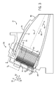
- FIG. 7 is a perspective view of an upstream end of an individual tube of the multi-tube fuel nozzle illustrating an air flow conditioner, taken within line 7 - 7 of FIG. 4 ;
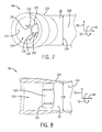
- FIG. 8 is a cutaway view of the upstream end of an individual tube of the multi-tube fuel nozzle of FIG. 7 illustrating details of an air flow conditioner.
- FIG. 9 is a cross-sectional side view of an embodiment of the mixing tube and cap face assembly, taken within line 9 - 9 of FIG. 6 ;
- FIG. 10 is a cross-sectional side view of an embodiment of the mixing tube and fuel injector illustrating an air flow conditioner, taken within line 10 - 10 of FIG. 6 ;
- FIG. 11 is a partial view of the embodiment of the mixing tube and fuel injector of FIG. 10 , illustrating details of air flow entering the tube;
- FIGS. 12-15 are a series of views of an embodiment of a multi-tube fuel nozzle and a combustor end cover, illustrating a method of removal of tubes of the multi-tube fuel nozzle.
- the present disclosure is directed to systems for conditioning air flow within a multi-tube fuel nozzle of a turbine system.
- the turbine system may include one or more multi-tube fuel nozzles.
- Each multi-tube fuel nozzle includes multiple mixing tubes (e.g. premixing tubes).
- Each tube includes an annular wall disposed about a central passage and an air inlet region configured to be disposed about a fuel injector extending into the central passage.
- the central passage extends from an upstream end of the annular wall of the tube to a downstream end of the annular wall relative to a direction of flow through the central passage.
- the air inlet region includes an outer surface of the annular wall that gradually decreases in diameter in the direction of flow.
- pressurized air may enter mixing tubes through the air inlet regions as the fuel injectors distribute fuel into the central passage, creating an air-fuel mixture.
- the air entry surface condition the air entering the mixing tubes and allow for substantially uniform mixing with the air before the mixture is subsequently directed into the combustion region.
- the air entry surface may be configured to target specific air side pressure drops, and best provide uniform air flow. Accordingly, the air entry surface may include a bell-shape.
- the air entry surface may include an inner surface that decreases in diameter along a portion of the air inlet region from the upstream end to the downstream end. A cross-sectional area within the inner surface of the air entry surface may decrease in the direction of flow.
- the air inlet region may include a contoured end that is configured to reduce pressure loss as air flows into the central passage through the air inlet region.
- the contoured end may include a contoured outer surface, a contoured inner surface, and a contoured turn portion disposed between the contoured outer surface and the contoured inner surface.
- the multi-tube fuel nozzle may comprise multiple premixer tubes, each premixer tube including the air inlet region. In the multi-tube fuel nozzle including multiple premixer tubes, clearances between the air entry surfaces of adjacent premixer tubes may be configured to accelerate a flow of air into each of the premixer tubes.
- the gas turbine system 10 includes one or more fuel nozzles 12 (e.g., multi-tube fuel nozzles), a fuel supply 14 , and a combustor 16 .
- the fuel nozzle 12 receives compressed air 18 from an air compressor 20 and fuel 22 from a fuel supply 14 .
- the present embodiments are discussed in context of air as an oxidant, the present embodiments may use air, oxygen, oxygen-enriched air, oxygen-reduced air, oxygen mixtures, or any combination thereof.
- the fuel nozzle 12 includes a plurality of fuel injectors 24 (e.g., 10 to 1000) and associated mixing tubes 26 (e.g., 10 to 1000), wherein each mixing tube 26 has an air flow conditioner 27 with an air entry surface 28 to direct and condition an air flow into the respective tube 26 , and each mixing tube 26 has a respective fuel injector 24 (e.g., in a coaxial or concentric arrangement) to inject fuel into the respective tube 26 .
- each mixing tube 26 mixes the air and fuel along its length, and then outputs an air-fuel mixture 30 into the combustor 16 .
- the mixing tubes 26 may be described as micromixing tubes, which may have diameters between approximately 0.5 to 2, 0.75 to 1.75, or 1 to 1.5 centimeters.
- the mixing tubes 26 may be arranged in one or more bundles (e.g., 1, 2, 3, 4, 5, 6, 7, 8, 9, 10, or more) of closely spaced tubes, generally in a parallel arrangement relative to one another.
- each mixing tube 26 is configured to mix (e.g., micromix) on a relatively small scale within each mixing tube 26 , which then outputs a fuel-air mixture 30 into the combustion chamber.
- the air flow conditioner 27 (e.g., with air entry surface 28 ) of the disclosed embodiments provides air conditioning on a tube level (i.e., for each individual mixing tube 26 ), such that the flow and/or pressure of air into each tube 26 and among the plurality of tubes 26 can be controlled to provide better mixing of fuel and air.
- the combustor 16 ignites the fuel-air mixture 30 , thereby generating pressurized exhaust gases 32 that flow into a turbine 34 .
- the pressurized exhaust gases 32 flow against and between blades in the turbine 34 , driving the turbine 34 to rotate.
- the turbine blades are coupled to a shaft 36 , which in turn also rotates as the exhaust gases 32 escape the combustor 16 .
- the exhaust 32 of the combustion process exits the turbine system 10 via an exhaust outlet 38 .
- Blades within the compressor 20 are additionally coupled to the shaft 36 , and rotate as the shaft 36 is driven to rotate by the turbine 34 .
- the rotation of the blades within the compressor 20 compresses air 40 that has been drawn into the compressor 20 by an air intake 42 .
- the resulting compressed air 18 is then fed into the multi-tube fuel nozzle 12 of the combustors 16 , as discussed above, where it is mixed with fuel 22 and ignited, creating a substantially self-sustaining process.
- the shaft 36 may be coupled to load 44 .
- the load 44 may be any suitable device that may generate power via the rotational output of a turbine system 10 , such as a power generation plant or an external mechanical load. The relationship between the consistency of the fuel-air mixture 30 and the efficient operation of the gas turbine system 10 can therefore be appreciated.
- the implementation of the multiple mixing tubes 26 each having an air entry surface 28 to condition the compressed air 18 will be discussed in greater detail below.
- FIG. 2 shows a cutaway side view of the embodiment of gas turbine system 10 of FIG. 1 .
- the embodiment includes a compressor 20 , which is coupled to an annular array of combustors 16 .
- Each combustor 16 includes at least one fuel nozzle 12 (e.g., a multi-tube fuel nozzle) which feeds the fuel-air mixture 30 to a combustion chamber 46 located within each combustor 16 .
- fuel nozzle 12 e.g., a multi-tube fuel nozzle
- certain embodiments of the mixing tubes 26 of the fuel nozzle 12 include unique features to more uniformly distribute the compressed air 18 creating a more uniform fuel-air mixture 30 . Uniformity of the fuel-air mixture 30 provides more efficient combustion, thereby increasing performance and reducing emissions.
- Combustion of the fuel-air mixture 30 within combustors 16 causes vanes or blades within the turbine 34 to rotate as exhaust gases 32 (e.g., combustion gases) pass toward an exhaust outlet 38 .
- exhaust gases 32 e.g., combustion gases
- a set of axes will be referenced. These axes are based on a cylindrical coordinate system and point in an axial direction 48 , a radial direction 50 , and a circumferential direction 52 .
- the axial direction 48 extends along a length or longitudinal axis 54 of the fuel nozzle 12
- the radial direction 50 extends away from the longitudinal axis 54
- the circumferential direction 52 extends around the longitudinal axis 54 .
- FIG. 3 is a cutaway side view of the combustor 16 of the gas turbine system 10 of FIG. 2 and taken within line 3 - 3 of FIG. 2 .
- the combustor 16 includes a head end 56 and a combustion chamber 46 .
- the fuel nozzle 12 is positioned within the head end 56 of the combustor 16 .
- Within the fuel nozzle 12 are suspended the multiple mixing tubes 26 (e.g. air-fuel pre-mixing tubes). Illustrated is an embodiment of the mixing tubes 26 having air flow conditioners 27 with air entry surfaces 28 that enable compressed air 18 to enter and mix with fuel 22 .
- the mixing tubes 26 generally extend axially between an end cover assembly 58 of the combustor 16 and a cap face assembly 60 of the fuel nozzle 12 .
- the mixing tubes 26 may be coupled to the end cover assembly 58 and the cap face assembly 60 , as further described below.
- the end cover assembly 58 may include a fuel inlet 62 and fuel plenum 64 for providing fuel 22 to multiple fuel injectors 24 .
- each individual fuel injector 24 is coupled to an individual mixing tube 26 .
- fuel 22 moves axially through each of the mixing tubes 26 from the end cover assembly 58 (via the fuel injectors 24 ) through the cap face assembly 60 and to the combustion chamber 46 .
- the direction of this movement along the longitudinal axis 54 of the fuel nozzle 12 will be referred to as the downstream direction 66 .
- the opposite direction will be referred to as the upstream direction 68 .
- the compressor 20 compresses air 40 received from the air intake 42 .
- the resulting flow of pressurized compressed air 18 is provided to the fuel nozzles 12 located in the head end 56 of the combustor 16 .
- the air enters the fuel nozzles 12 through air inlets 70 to be used in the combustion process.
- the pressurized air 18 flows from the compressor 20 in an upstream direction 68 through an annulus 72 formed between a liner 74 (e.g., an annular liner) and a flow sleeve 76 (e.g., and annular flow sleeve) of the combustor 16 .
- a liner 74 e.g., an annular liner
- a flow sleeve 76 e.g., and annular flow sleeve
- the compressed air 18 is forced into the air inlets 70 of the fuel nozzle 12 and fills an air plenum 78 within the fuel nozzle 12 .
- the pressurized air 18 in the air plenum 78 then enters the multiple mixing tubes 26 through the air entry surfaces 28 of the air flow conditioner 27 .
- the air entry surface 28 of the air flow conditioner 27 may condition the air 18 in various ways, as discussed further below.
- the air 18 is then mixed with the fuel 22 provided by the fuel injectors 24 .
- the fuel-air mixture 30 flows in a downstream direction 66 from the mixing tubes 26 into the combustion chamber 46 , where it is ignited and combusted to form the combustion gases 32 (e.g., exhaust gases).
- the combustion gases 32 flow from the combustion chamber 46 in the downstream direction 66 to a transition piece 80 .
- the combustion gases 22 then pass from the transition piece 80 to the turbine 34 , where the combustion gases 22 drive the rotation of the blades within the turbine 34 .
- FIG. 4 illustrates an exploded perspective view of the multi-tube fuel nozzle 12 taken within line 4 - 4 of FIG. 3 .
- This figure further illustrates the arrangement, according to some embodiments, of the multiple fuel injectors 24 on the end cover 58 and their relation to the multiple mixing tubes 26 .
- the mixing tubes 26 are arranged to be axially 48 disposed between the end cover assembly 58 and the cap face assembly 60 .
- the individual mixing tubes 26 are each paired with an individual fuel injector 24 and are configured to be disposed about that fuel injector 24 (e.g., in a coaxial or concentric arrangement).
- the air entry surfaces 28 are located on a first end (e.g., the upstream 68 end) of the mixing tubes 26 in proximity to the fuel injectors 24 .
- the fuel injectors 24 may be removably coupled to the end cover assembly 58 .
- FIG. 4 illustrates a support structure 82 (e.g., annular barrel, fuel nozzle cap) of the fuel nozzle 12 that surrounds the mixing tubes 26 and other structures within the fuel nozzle 12 .
- the support structure 82 extends from the end cover assembly 58 to the cap face assembly 60 , generally protects and supports the structures positioned within the fuel nozzle 12 , and defines the air plenum 78 within the fuel nozzle 12 .
- the air inlets 70 are located on the support structure 82 and direct the compressed air 18 radially into the air plenum 78 on the interior of the fuel nozzle 12 .
- a retainer plate 84 is located upstream 68 and proximate to the removable cap face assembly 60 .
- the nozzle 12 includes an annular air flow conditioning diffuser 86 surrounding the air inlets 70 .
- FIG. 5 is a partial cross-sectional side view of the combustor 16 as taken within line 5 - 5 of FIG. 3 .
- the head end 56 of the combustor 16 contains a portion of the multi-tube fuel nozzle 12 .
- the support structure 82 surrounds the multi-tube fuel nozzle 12 and the multiple mixing tubes 26 .
- each mixing tube 26 may extend axially between the end cover assembly 58 and the cap face assembly 60 .
- the mixing tubes 26 may further extend through the cap face assembly 60 to feed the fuel-air mixture 30 directly to the combustion chamber 46 .
- Each mixing tube 26 is positioned to surround a fuel injector 24 (e.g., coaxial or concentric arrangement), such that the injector 24 receives fuel 22 from the fuel plenum 64 and directs the fuel into the tube 26 .
- the fuel plenum 64 is fed fuel 22 entering the fuel inlet 62 located on the end cover assembly 58 .
- compressed air 18 enters the fuel nozzle 12 through air inlets 70 , which may be surrounded by a diffuser 86 .
- the diffuser 86 may be annular and configured to pre-condition and distribute the pressurized air into the fuel nozzle 12 across the mixing tubes 26 in a variety of directions.
- the direction of the air flow within the fuel nozzle 12 will be substantially radially inward 88 , but may have an upstream 68 component or downstream 66 component.
- the air flow will vary across mixing tubes 26 that are located in more radially outward 90 locations within the fuel nozzle 12 , closer to the air inlets 70 .
- the pressurized air 18 enters each mixing tube 26 through an air entry surface 28 of an air flow conditioner 27 .
- the configuration of the air entry surfaces 28 of the air flow conditioners 27 is varied among individual mixing tubes 26 based on their radial 50 locations within the fuel nozzle air plenum 78 . This customization can compensate for the variations in air pressure and movement across the mixing tubes 26 , namely the pressure drop that occurs in the radially inward 88 direction.
- the axial 48 position of the air entry surfaces 28 along the mixing tubes 26 may be varied to compensate for axial 48 variations in air pressure.
- the air entry surfaces 28 of the air flow conditioner 27 located on an upstream end 94 (e.g., a first end) of the mixing tube 26 may be configured to have any of a variety of shapes, sizes, and arrangements as will be further discussed below.
- the retainer plate 84 and/or an impingement plate 92 may be positioned within the fuel nozzle 12 surrounding the downstream end 96 of the mixing tubes 26 generally proximate to the cap face assembly 60 .
- the impingement plate 92 may include a plurality of impingement cooling orifices, which may direct jets of air to impinge against a rear surface of the cap face assembly 60 to provide impingement cooling.
- FIG. 6 is a front view of an embodiment of the multi-tube fuel nozzle 12 illustrating the radial layout of the multiple mixing tubes 26 .
- the illustrated nozzle 12 includes multiple sectors 98 arranged circumferentially 52 on the cap face assembly 60 .
- the arrangement of the mixing tubes 26 affects the clearances between the tubes 26 , and also the clearances between the air entry surfaces 28 among adjacent tubes 26 .
- the illustrated nozzle 12 includes a single liquid fuel cartridge 100 placed in between each sector 98 , and an additional liquid fuel cartridge 100 in the center of the cap face assembly 60 .
- the liquid fuel cartridges 100 supply the fuel nozzle 12 with liquid fuel 22 .
- each sector 98 includes of multiple rows 102 of mixing tubes 26 , each row 102 having two or more tubes 26 .
- the circumferential distance 104 between each tube 26 in each row 102 is substantially equal.
- the radial distance 106 between each row 102 in each sector 98 is also substantially equal. This results in substantially equal clearances between the tubes 26 and equal clearances between the air entry surfaces 28 of the tubes 26 .
- there may be different numbers of sectors 98 For example, there may be 1 to 20 sectors 98 (e.g., 2, 3, 4, 5, 6, 7, 8, 9, or 10).
- Each sector 98 may have various numbers of mixing tubes 26 .
- each sector may have 50, 100, 150, 200, or any other number of tubes 26 .
- the tubes 26 may be arranged with non-uniform spacing (e.g., varying circumferential distance 104 and/or radial distance 106 ) to manage any air pressure drops within the fuel nozzle 12 .
- the circumferential space 104 between adjacent tubes 26 can be varied based on their proximity to the air inlets 70 .
- the circumferential space 104 between the tubes 26 may be greater at locations with closer proximity to air inlets 70 (e.g., where air pressure is greater) and decreased at locations within the fuel nozzle 12 (e.g., where air pressure has dropped). This arrangement may more evenly distribute air pressure around the circumference 52 of the fuel nozzle.
- tubes 26 can sustain flow conditions of compressed air 18 prior to entry into the mixing tubes 26 so that the conditions (e.g., pressure, velocity) may be substantially matched to flow conditions of the compressed air after entering the tubes 26 .
- the radial distance 106 between rows 96 may similarly vary based on their proximity to the air inlets 70 to manage air pressure and velocity radially within the fuel nozzle 12 .
- the arrangement of the individual tubes 26 may be determined to compensate for pressure drops that may occur inside the fuel nozzle 12 due to other structures, such as the liquid fuel cartridges 100 . For example, a structure may cause a disturbance in fuel pressure, and such disturbance can be reduced or avoided by the placement of mixing tubes 26 .
- FIG. 7 is a perspective view of an upstream end 94 of an individual tube 26 of the multi-tube fuel nozzle 12 defined by an annular wall 108 .
- the tube 26 includes a central passage 110 disposed within the annular wall 108 , wherein supports structures 112 extend radially inward from an inner surface 114 of the tube 26 to a support ring 116 .
- the support structures 112 and the support ring 116 support the fuel injector 24 within the mixing tube 26 , thereby limiting radial movement of the fuel injector 24 relative to the tube 26 .
- the individual support structures 112 may be of any shape or size that will give adequate foundation for the support ring 116 , while also allowing air flow past the support structures 112 .
- the edges 118 of the support structures 112 may be angular or contoured, or have a combination or angular and contoured surfaces.
- the support structured 112 may have an airfoil shaped cross-section to reduce flow resistance.
- the depth 120 of the support structures 112 may vary, and each individual support structure 112 may be located within the mixing tube 26 at positions further upstream 68 or downstream 66 in order to better manage any disturbance of pressurized air 18 .
- the support ring 116 may also be of different shapes and sizes.
- the edges 122 of the support ring 116 may be angular, contoured, or have a combination of angular and contoured surfaces.
- the outer surface 124 of the annular wall 108 of the mixing tube 26 decreases in diameter 126 from upstream end 94 to downstream end 96 of the annular wall 108 .
- This configuration may allow for smooth movement of air flow in an axial 48 direction across the outer surface 124 of the annular wall 108 of the mixing tube 26 .
- the diameter 126 of the outer surface 124 may stay constant or may increase along the downstream 66 axial 48 direction.
- These various configurations may allow for variable management of the air 18 flow. For example, for mixing tubes 26 located in more radially 50 inward locations within the fuel nozzle 12 , air pressure of the air 18 entering the fuel nozzle 12 may be lower in areas further away from the air inlets 70 of the fuel nozzle 12 . This decrease in air pressure may be compensated for by an increased diameter 126 of the outer surfaces 124 of the mixing tubes 26 , decreasing the available volume on the outside of and between the mixing tubes 26 . This decrease in available volume helps to accelerate air flow into the air inlets 28 .
- FIG. 8 is a cutaway perspective view of the same upstream end 88 of the mixing tube 26 . Shown are the support structures 112 and support ring 116 disposed within the inner surface 114 of the mixing tube 26 .
- the inner surface 114 has a diameter 128 that is constant from upstream end 94 to downstream end 96 of the annular wall 108 .
- the constant diameter 128 of the inner surface 114 of the mixing tube 26 enables selective management of airflow within the central passage 110 of the mixing tube 26 .
- the constant inner diameter 128 allows for smooth movement of air flow, avoiding wakes, separations and losses that may occur due to blockage of fuel flow.
- the decrease in diameter 128 changes in the internal volume of the inner passage 110 allowing management of air pressure within the mixing tube 26 .
- Mixing tubes 26 may be configured to have a larger or smaller outer diameter 126 , and greater of lesser changes in outer diameter 126 in the axial direction to customize air flow depending on location of the tube 26 within the fuel nozzle 12 .
- FIG. 9 is a cross-sectional side view of an embodiment of the downstream end 96 of the mixing tube 26 as assembled with the cap face assembly 60 , taken within line 9 - 9 of FIG. 6 . Illustrated is an embodiment of the spatial relationship among the mixing tubes 26 , the cap face assembly 60 , and/or the end cover assembly 58 .
- the mixing tubes 26 may be attached to components within the head end 56 of the combustor 16 , such as the cap face assembly 60 , the retainer plate 84 , and/or the impingement plate 92 by various fasteners or connections, such as weld, brazed joints, brackets, threaded fasteners, snap-fits, joints, or other connections.
- the mixing tubes 26 are held in a floating configuration and are merely supported by one or more of the cap face assembly 60 , the retainer plate 84 , the impingement plate 92 , various springs, or other supporting structures.
- Such floating configurations may advantageously accommodate thermal growth of the mixing tubes 18 and other components of the combustor 14 .
- Floating configurations also allow the customization and configuration of mixing tubes 26 with various air port 28 configurations to be more easily made. If fuel-air mixtures 20 are found to be non-uniform, individual tubes 26 may be easily removed and replaced with tubes 26 that have different air port 28 (e.g. air flow conditioner 27 ) configurations that better compensate for air pressure variations within the fuel nozzle 12 .
- the floating configurations may additionally be implemented by the inclusion of an axial spring 130 to provide resilient axial 48 support and constraint to the movement of the mixing tubes 26 .
- the axial spring 130 may be positioned between a retainer plate 84 and impingement plate 92 .
- There may further be features implemented such as additional springs, channels and/or guides, to block radial 50 or circumferential 52 movement of the mixing tubes 26 .
- FIG. 10 is a cross-sectional side view of an embodiment of the mixing tube 26 installed about the fuel injector 24 , as taken within line 10 - 10 of FIG. 6 .
- the fuel injector 24 is positioned on the head end 56 of the fuel nozzle 12 and receives fuel from the fuel plenum 64 .
- the fuel injector 24 may be generally positioned within the central passage 110 in the first end 94 of each mixing tube 26 .
- This first end 94 is located on the upstream 68 side of the multi-tube fuel nozzle 12 , adjacent to the end cover assembly 58 .
- the air entry surfaces 28 are located on this first end 94 generally proximate or adjacent to the head end 56 .
- the fuel injector 24 may extend further downstream and the air inlets 28 may accordingly also be located in locations further downstream 66 from the head end 56 .
- the configuration of the air inlets 28 can further be configured to manage air 18 flow within the central passage 110 of the mixing tube 26 .
- the outer surface 124 of the annular wall 108 of an individual mixing tube 26 may have a diameter 126 that decreases along the axial 48 downstream 66 direction, improving the air flow on the exterior of the mixing tubes 26 .
- the inner surface 114 of the annular wall 108 of the mixing tube 26 may have a diameter 128 that is constant along the axial 48 downstream 66 direction, avoiding disturbances in the flow of pressurized air 18 within the central passage 110 of the mixing tube 26 .
- the tube 26 also includes a turn portion 134 between the outer surface 124 of the annular wall 108 and inner surface 114 of the annular wall 108 wherein the turn portion 134 (e.g., contoured turn portion) connects the inner 114 and outer surfaces 124 of the mixing tube 26 annular wall 108 .
- This turn portion 134 of the tube 26 may be angular (e.g., conical surface) or contoured (e.g., curved annular surface) in order to minimize and manage air flow disturbances as pressurized air 18 enters the central passage 110 .
- the turn portion 122 may help gradually turn the air flow into the tube 26 , while helping to eliminate any low velocity regions a generation of turbulence.
- the upstream end 94 of the mixing tube may form a bell-shape, e.g., a curved annular surface that gradually decreases in diameter 126 in a curved manner.
- Fuel is delivered to a central passage 136 of the fuel injector 24 and is dispersed through fuel ports 138 into the central passage 110 of the mixing tube 26 .
- the fuel ports 138 are located on the tapered portion 140 , which may have a linear or curved taper in the downstream direction 66 .
- the tapered portion 140 may be formed as a conical wall, an inwardly curved annular wall (e.g., curved inwardly toward the axis of the injector 24 ), an outwardly curved annular wall (e.g., curved outwardly away from the axis of the injector 24 ), or a combination thereof.
- a tapered portion 140 extends from a first position upstream 68 of the air ports 28 to a second position downstream 66 of the air ports 28 of the mixing tube 26 .
- the tapered portion 140 of the fuel injector 24 gradually decreases in diameter (i.e., converges) in the downstream direction 66 , thereby gradually increasing the cross-sectional area between the fuel injector 24 and the mixing tube 26 in the downstream direction 66 .
- the illustrated embodiment provides a gradual pressure drop between the fuel injector 24 and the mixing tube 26 , thereby helping to improve the flow and mixing of fuel and air.
- the air flow conditioner 27 e.g., air inlet 28
- the fuel ports 138 along the fuel injector 24 e.g., tapered portion 140
- the illustrated air inlet 28 is disposed upstream of the fuel ports 138 to increase the pressure upstream of the fuel ports 138 .
- FIG. 11 shows a portion of the embodiment of the mixing tube and fuel injector of FIG. 11 , illustrating details of the flow of pressurized air 18 as it enters the mixing tube 26 and is conditioned by the air flow conditioner 27 .
- contouring of the outer surface 124 of the tube 26 facilitates accelerated movement 150 of the pressurized air along the outer surface 124 of the tubes 26 . Clearances between adjacent tubes are designed to match flow conditions prior entry into the tube and after entry to the tube and to accelerate incoming air flow 152 into the tubes.
- the contouring along the turn portion 134 of the annular wall that defines the mixing tube 26 acts to gradually increase cross-sectional area of the tube 144 at the turn portion and reduce turning losses in pressure.
- the cross-sectional area 146 also gradually decreases until it is constant 148 in downstream portions of the tube. This decrease in cross-sectional area defines the bell shaped portion of the tube 26 .
- the gradual contour of the turn portion 134 is located at the upstream end of the bell shaped portion and minimizes flow separation, and provides a preferable pressure and velocity profile for the incoming air 152 .
- the increased axial movement 154 of the air 18 upstream of the fuel ports 138 on the fuel injector 24 act to minimize blockage of fuel 22 entering 156 the mixing tube 26 and improve mixing of fuel 22 and air 18 .
- Overall pressure drops are reduced and flame-holding risks are mitigated by the contoured surfaces 124 , 134 , and 114 .
- FIGS. 12-15 are perspective views of the fuel nozzle 12 , illustrating a series of steps of a method for removing at least one mixing tube 26 in accordance with certain embodiments.
- the multi-tube fuel nozzle 12 is removed from the head end 56 of the combustor 16 and coupled to the end cover assembly 58 .
- Illustrated is the end cover assembly 58 with fuel inlet 62 coupled with the support structure 82 and cap face assembly 60 .
- the end cover assembly 58 is separated 158 from the support structure 82 and cap face assembly 60 .
- FIG. 13 reveals the fuel injectors 24 coupled to the end cover assembly 58 of the fuel nozzle 12 .
- FIG. 13 reveals the fuel injectors 24 coupled to the end cover assembly 58 of the fuel nozzle 12 .
- the retainer plate 84 is removed from the cap face assembly 60 by sliding the retainer plate 84 along the mixing tubes 26 in an upstream 68 direction from the second end 96 to the first end 94 of the mixing tubes 26 . As shown in FIG. 15 , the mixing tubes 26 may then be removed from their location on the cap face assembly 60 . Removal of one or more mixing tubes 26 may allow for inspection, replacement, repair, or any other purpose found in the course of manufacturing, installation, and operation of the fuel nozzle 12 . Installation of mixing tubes 26 is achieved by following the steps illustrated in FIGS. 12-15 in reverse order. Namely, the one or more mixing tubes 26 may be inserted in place on the cap face assembly 60 ( FIG.
- the retainer plate 84 installed by sliding across the mixing tubes 26 from the first end 94 to the second end 96 , until the tubes 26 are flush with the cap face assembly 60 and/or impingement plate 92 ( FIG. 14 ).
- the support structure 82 is then coupled with the end cover assembly 58 by aligning the mixing tubes 26 with their respective fuel injectors 24 ( FIG. 13 ).
- the assembled fuel nozzle 12 ( FIG. 12 ) may then be installed into the head end 56 of the combustor 12 .
- the fuel nozzle 12 is equipped with multiple mixing tubes 26 having air inlets 28 through which pressurized compressed air 18 that enters the fuel nozzle 12 is directed and mixes with fuel 22 injected by multiple fuel injectors 24 .
- the air inlets 28 may be configured with different shapes, sizes, spatial arrangements, and configured to direct the air at various angles. This customization increases mixing and uniformity, compensating for the varying air 18 and fuel 22 pressures among the multiple fuel injectors 24 in the multi-tube fuel nozzle 12 .
- the increased mixing of the air 18 and the fuel 22 increases the flame stability within the combustor 16 and reduces the amount of undesirable combustion byproducts.
- the method of removal and replacement of individual mixing tubes 26 allows for cost-effective and efficient repair of the fuel nozzle 12 .
Landscapes
- Engineering & Computer Science (AREA)
- Chemical & Material Sciences (AREA)
- Combustion & Propulsion (AREA)
- Mechanical Engineering (AREA)
- General Engineering & Computer Science (AREA)
- Nozzles (AREA)
- Gas Burners (AREA)
Abstract
Description
Claims (20)
Priority Applications (5)
| Application Number | Priority Date | Filing Date | Title |
|---|---|---|---|
| US13/797,986 US9765973B2 (en) | 2013-03-12 | 2013-03-12 | System and method for tube level air flow conditioning |
| DE102014102780.9A DE102014102780B4 (en) | 2013-03-12 | 2014-03-03 | Raw level airflow conditioning system |
| CH00323/14A CH707769A8 (en) | 2013-03-12 | 2014-03-05 | Tube level airflow conditioning system in a multi-tube fuel nozzle. |
| JP2014044466A JP6401463B2 (en) | 2013-03-12 | 2014-03-07 | System and method for air flow regulation at tube level |
| CN201420111518.8U CN204063126U (en) | 2013-03-12 | 2014-03-12 | For the system that pipe horizontal gas flow regulates |
Applications Claiming Priority (1)
| Application Number | Priority Date | Filing Date | Title |
|---|---|---|---|
| US13/797,986 US9765973B2 (en) | 2013-03-12 | 2013-03-12 | System and method for tube level air flow conditioning |
Publications (2)
| Publication Number | Publication Date |
|---|---|
| US20140338338A1 US20140338338A1 (en) | 2014-11-20 |
| US9765973B2 true US9765973B2 (en) | 2017-09-19 |
Family
ID=51419031
Family Applications (1)
| Application Number | Title | Priority Date | Filing Date |
|---|---|---|---|
| US13/797,986 Active 2035-06-30 US9765973B2 (en) | 2013-03-12 | 2013-03-12 | System and method for tube level air flow conditioning |
Country Status (5)
| Country | Link |
|---|---|
| US (1) | US9765973B2 (en) |
| JP (1) | JP6401463B2 (en) |
| CN (1) | CN204063126U (en) |
| CH (1) | CH707769A8 (en) |
| DE (1) | DE102014102780B4 (en) |
Cited By (3)
| Publication number | Priority date | Publication date | Assignee | Title |
|---|---|---|---|---|
| US11454396B1 (en) * | 2021-06-07 | 2022-09-27 | General Electric Company | Fuel injector and pre-mixer system for a burner array |
| US20240200521A1 (en) * | 2021-04-26 | 2024-06-20 | Rolls-Royce Deutschland Ltd & Co Kg | Fuel nozzle having different first and second discharge orifices for providing a hydrogen-air mixture |
| US12553610B1 (en) | 2024-12-04 | 2026-02-17 | General Electric Company | Gas turbine engine including a fuel nozzle having vortex generators |
Families Citing this family (32)
| Publication number | Priority date | Publication date | Assignee | Title |
|---|---|---|---|---|
| US9534781B2 (en) | 2012-05-10 | 2017-01-03 | General Electric Company | System and method having multi-tube fuel nozzle with differential flow |
| US9347668B2 (en) | 2013-03-12 | 2016-05-24 | General Electric Company | End cover configuration and assembly |
| US9671112B2 (en) | 2013-03-12 | 2017-06-06 | General Electric Company | Air diffuser for a head end of a combustor |
| US9765973B2 (en) | 2013-03-12 | 2017-09-19 | General Electric Company | System and method for tube level air flow conditioning |
| US9759425B2 (en) * | 2013-03-12 | 2017-09-12 | General Electric Company | System and method having multi-tube fuel nozzle with multiple fuel injectors |
| US20140338340A1 (en) * | 2013-03-12 | 2014-11-20 | General Electric Company | System and method for tube level air flow conditioning |
| US9528444B2 (en) | 2013-03-12 | 2016-12-27 | General Electric Company | System having multi-tube fuel nozzle with floating arrangement of mixing tubes |
| US9534787B2 (en) | 2013-03-12 | 2017-01-03 | General Electric Company | Micromixing cap assembly |
| US9366439B2 (en) | 2013-03-12 | 2016-06-14 | General Electric Company | Combustor end cover with fuel plenums |
| US9650959B2 (en) | 2013-03-12 | 2017-05-16 | General Electric Company | Fuel-air mixing system with mixing chambers of various lengths for gas turbine system |
| US9651259B2 (en) | 2013-03-12 | 2017-05-16 | General Electric Company | Multi-injector micromixing system |
| US9291352B2 (en) | 2013-03-15 | 2016-03-22 | General Electric Company | System having a multi-tube fuel nozzle with an inlet flow conditioner |
| US9303873B2 (en) | 2013-03-15 | 2016-04-05 | General Electric Company | System having a multi-tube fuel nozzle with a fuel nozzle housing |
| US9316397B2 (en) | 2013-03-15 | 2016-04-19 | General Electric Company | System and method for sealing a fuel nozzle |
| US9784452B2 (en) | 2013-03-15 | 2017-10-10 | General Electric Company | System having a multi-tube fuel nozzle with an aft plate assembly |
| US9546789B2 (en) | 2013-03-15 | 2017-01-17 | General Electric Company | System having a multi-tube fuel nozzle |
| US9476592B2 (en) * | 2013-09-19 | 2016-10-25 | General Electric Company | System for injecting fuel in a gas turbine combustor |
| CN107429920B (en) * | 2014-11-21 | 2019-11-05 | 安萨尔多能源英国知识产权有限公司 | Flame front burner determines the bushing of shape |
| US20180231253A1 (en) * | 2017-02-16 | 2018-08-16 | General Electric Company | Object with tear-shaped suspension for annular bodies |
| US11293641B2 (en) | 2017-02-16 | 2022-04-05 | General Electric Company | Object with tear-shaped suspension for annular bodies |
| US11525578B2 (en) * | 2017-08-16 | 2022-12-13 | General Electric Company | Dynamics-mitigating adapter for bundled tube fuel nozzle |
| KR102066042B1 (en) * | 2017-10-31 | 2020-01-14 | 두산중공업 주식회사 | Combustor and gas turbine including the same |
| JP6995696B2 (en) * | 2018-05-28 | 2022-01-17 | 三菱重工業株式会社 | Fuel injection system and gas turbine |
| US12553385B2 (en) | 2020-03-30 | 2026-02-17 | Ge Vernova Infrastructure Technology Llc | Compact turbomachine combustor |
| KR102460672B1 (en) * | 2021-01-06 | 2022-10-27 | 두산에너빌리티 주식회사 | Fuel nozzle, fuel nozzle module and combustor having the same |
| CN112856483B (en) * | 2021-01-12 | 2022-07-15 | 哈尔滨工业大学 | A humidified micro-mix burner |
| KR102460001B1 (en) * | 2021-02-17 | 2022-10-26 | 두산에너빌리티 주식회사 | Micromixer module and combustor having the same |
| FR3121973A1 (en) * | 2021-04-19 | 2022-10-21 | Safran Aircraft Engines | DIFFUSION CONE FOR THE REAR PART OF A TURBOJET INTEGRATING A FLAME HOLDER RING AT THE TRAILING EDGE |
| US12405007B2 (en) | 2021-12-03 | 2025-09-02 | General Electric Company | Combustor size rating for a gas turbine engine using hydrogen fuel |
| US11815269B2 (en) | 2021-12-29 | 2023-11-14 | General Electric Company | Fuel-air mixing assembly in a turbine engine |
| JP2023131352A (en) * | 2022-03-09 | 2023-09-22 | 三菱重工業株式会社 | Combustor and gas turbine |
| CN118481838B (en) * | 2024-05-28 | 2025-09-19 | 厦门大学 | Pure hydrogen fuel injection blending structure based on micro-mixing array distributed control |
Citations (164)
| Publication number | Priority date | Publication date | Assignee | Title |
|---|---|---|---|---|
| US1855165A (en) | 1926-06-04 | 1932-04-19 | Barker Maurice Eugene | Apparatus and process for muffling and purifying exhaust gases |
| US2564042A (en) | 1946-02-27 | 1951-08-14 | Power Jets Res & Dev Ltd | Turbo-jet engine with axially expansible exhaust duct controlling area of exhaust bypass gap |
| US3581492A (en) | 1969-07-08 | 1971-06-01 | Nasa | Gas turbine combustor |
| US3751911A (en) | 1970-04-18 | 1973-08-14 | Motoren Turbinen Union | Air inlet arrangement for gas turbine engine combustion chamber |
| US4100733A (en) | 1976-10-04 | 1978-07-18 | United Technologies Corporation | Premix combustor |
| US4408461A (en) | 1979-11-23 | 1983-10-11 | Bbc Brown, Boveri & Company Limited | Combustion chamber of a gas turbine with pre-mixing and pre-evaporation elements |
| US4587809A (en) | 1981-06-15 | 1986-05-13 | Hitachi, Ltd. | Premixing swirling burner |
| US4763481A (en) | 1985-06-07 | 1988-08-16 | Ruston Gas Turbines Limited | Combustor for gas turbine engine |
| US4796429A (en) | 1976-11-15 | 1989-01-10 | General Motors Corporation | Combustor diffuser |
| US5121597A (en) | 1989-02-03 | 1992-06-16 | Hitachi, Ltd. | Gas turbine combustor and methodd of operating the same |
| US5161366A (en) | 1990-04-16 | 1992-11-10 | General Electric Company | Gas turbine catalytic combustor with preburner and low nox emissions |
| US5235814A (en) | 1991-08-01 | 1993-08-17 | General Electric Company | Flashback resistant fuel staged premixed combustor |
| US5274991A (en) * | 1992-03-30 | 1994-01-04 | General Electric Company | Dry low NOx multi-nozzle combustion liner cap assembly |
| US5361586A (en) | 1993-04-15 | 1994-11-08 | Westinghouse Electric Corporation | Gas turbine ultra low NOx combustor |
| US5410884A (en) | 1992-10-19 | 1995-05-02 | Mitsubishi Jukogyo Kabushiki Kaisha | Combustor for gas turbines with diverging pilot nozzle cone |
| US5415000A (en) | 1994-06-13 | 1995-05-16 | Westinghouse Electric Corporation | Low NOx combustor retro-fit system for gas turbines |
| US5515680A (en) | 1993-03-18 | 1996-05-14 | Hitachi, Ltd. | Apparatus and method for mixing gaseous fuel and air for combustion including injection at a reverse flow bend |
| US5611196A (en) | 1994-10-14 | 1997-03-18 | Ulstein Turbine As | Fuel/air mixing device for gas turbine combustor |
| US5675971A (en) | 1996-01-02 | 1997-10-14 | General Electric Company | Dual fuel mixer for gas turbine combustor |
| US5778676A (en) | 1996-01-02 | 1998-07-14 | General Electric Company | Dual fuel mixer for gas turbine combustor |
| US5816049A (en) | 1997-01-02 | 1998-10-06 | General Electric Company | Dual fuel mixer for gas turbine combustor |
| US5822992A (en) | 1995-10-19 | 1998-10-20 | General Electric Company | Low emissions combustor premixer |
| US5901555A (en) | 1996-02-05 | 1999-05-11 | Mitsubishi Heavy Industries, Ltd. | Gas turbine combustor having multiple burner groups and independently operable pilot fuel injection systems |
| US5927076A (en) | 1996-10-22 | 1999-07-27 | Westinghouse Electric Corporation | Multiple venturi ultra-low nox combustor |
| US5943866A (en) | 1994-10-03 | 1999-08-31 | General Electric Company | Dynamically uncoupled low NOx combustor having multiple premixers with axial staging |
| US6016658A (en) | 1997-05-13 | 2000-01-25 | Capstone Turbine Corporation | Low emissions combustion system for a gas turbine engine |
| US6026645A (en) | 1998-03-16 | 2000-02-22 | Siemens Westinghouse Power Corporation | Fuel/air mixing disks for dry low-NOx combustors |
| US6038861A (en) | 1998-06-10 | 2000-03-21 | Siemens Westinghouse Power Corporation | Main stage fuel mixer with premixing transition for dry low Nox (DLN) combustors |
| US6092363A (en) | 1998-06-19 | 2000-07-25 | Siemens Westinghouse Power Corporation | Low Nox combustor having dual fuel injection system |
| US20010052229A1 (en) | 1998-02-10 | 2001-12-20 | General Electric Company | Burner with uniform fuel/air premixing for low emissions combustion |
| US6334309B1 (en) | 1999-05-31 | 2002-01-01 | Nuovo Pignone Holding S.P.A | Liquid fuel injector for burners in gas turbines |
| US20020014078A1 (en) | 2000-07-13 | 2002-02-07 | Shigemi Mandai | Fuel discharge member, a burner, a premixing nozzle of a combustor, a combustor, a gas turbine, and a jet engine |
| US6351948B1 (en) | 1999-12-02 | 2002-03-05 | Woodward Fst, Inc. | Gas turbine engine fuel injector |
| US6360776B1 (en) | 2000-11-01 | 2002-03-26 | Rolls-Royce Corporation | Apparatus for premixing in a gas turbine engine |
| US6363724B1 (en) | 2000-08-31 | 2002-04-02 | General Electric Company | Gas only nozzle fuel tip |
| US6438959B1 (en) | 2000-12-28 | 2002-08-27 | General Electric Company | Combustion cap with integral air diffuser and related method |
| US20020119412A1 (en) | 2001-02-24 | 2002-08-29 | Loving Ronald E. | Multi-fueled multi-use combustion chamber |
| US20020128790A1 (en) | 2001-03-09 | 2002-09-12 | Donald Woodmansee | System and method of automated part evaluation including inspection, disposition recommendation and refurbishment process determination |
| US20020192615A1 (en) | 1999-12-15 | 2002-12-19 | Koji Moriya | Fluid distributor,burner device, gas turbine engine, and cogeneration system |
| US20030014975A1 (en) | 2001-06-29 | 2003-01-23 | Mitsubishi Heavy Industries, Ltd. | Gas turbine combustor |
| US20030037549A1 (en) * | 2001-08-24 | 2003-02-27 | Mitsubishi Heavy Industries, Ltd. | Gas turbine combustor |
| US6530222B2 (en) | 2001-07-13 | 2003-03-11 | Pratt & Whitney Canada Corp. | Swirled diffusion dump combustor |
| US6532742B2 (en) | 1999-12-16 | 2003-03-18 | Rolls-Royce Plc | Combustion chamber |
| US20030089801A1 (en) | 2001-11-14 | 2003-05-15 | Mitsubishi Heavy Industries Ltd. | Combustor containing fuel nozzle |
| US20040006991A1 (en) | 2002-07-15 | 2004-01-15 | Peter Stuttaford | Fully premixed secondary fuel nozzle with improved stability and dual fuel capability |
| US20040006990A1 (en) | 2002-07-15 | 2004-01-15 | Peter Stuttaford | Fully premixed secondary fuel nozzle with improved stability |
| US20040006993A1 (en) | 2002-07-15 | 2004-01-15 | Peter Stuttaford | Dual fuel fin mixer secondary fuel nozzle |
| US20040006992A1 (en) | 2002-07-15 | 2004-01-15 | Peter Stuttaford | Gas only fin mixer secondary fuel nozzle |
| US6705087B1 (en) * | 2002-09-13 | 2004-03-16 | Siemens Westinghouse Power Corporation | Swirler assembly with improved vibrational response |
| US20040060297A1 (en) | 2002-09-26 | 2004-04-01 | Siemens Westinghouse Power Corporation | Turbine engine fuel nozzle |
| US20040142294A1 (en) | 2001-05-10 | 2004-07-22 | Tidjani Niass | Device and method for injecting a liquid fuel into an air flow for a combustion chamber |
| US6880340B2 (en) | 2001-06-07 | 2005-04-19 | Mitsubishi Heavy Industries, Ltd. | Combustor with turbulence producing device |
| US6928823B2 (en) | 2001-08-29 | 2005-08-16 | Hitachi, Ltd. | Gas turbine combustor and operating method thereof |
| US6983600B1 (en) | 2004-06-30 | 2006-01-10 | General Electric Company | Multi-venturi tube fuel injector for gas turbine combustors |
| US7007486B2 (en) | 2003-03-26 | 2006-03-07 | The Boeing Company | Apparatus and method for selecting a flow mixture |
| US7007478B2 (en) | 2004-06-30 | 2006-03-07 | General Electric Company | Multi-venturi tube fuel injector for a gas turbine combustor |
| US7021562B2 (en) | 2002-11-15 | 2006-04-04 | Parker-Hannifin Corp. | Macrolaminate direct injection nozzle |
| US7134287B2 (en) | 2003-07-10 | 2006-11-14 | General Electric Company | Turbine combustor endcover assembly |
| US7171813B2 (en) | 2001-06-29 | 2007-02-06 | Mitsubishi Heavy Metal Industries, Ltd. | Fuel injection nozzle for gas turbine combustor, gas turbine combustor, and gas turbine |
| US7181916B2 (en) | 2004-04-12 | 2007-02-27 | General Electric Company | Method for operating a reduced center burner in multi-burner combustor |
| US7284378B2 (en) | 2004-06-04 | 2007-10-23 | General Electric Company | Methods and apparatus for low emission gas turbine energy generation |
| US20070289305A1 (en) | 2005-12-13 | 2007-12-20 | Kawasaki Jukogyo Kabushiki Kaisha | Fuel spraying apparatus of gas turbine engine |
| US20080053097A1 (en) | 2006-09-05 | 2008-03-06 | Fei Han | Injection assembly for a combustor |
| US20080078179A1 (en) | 2004-11-09 | 2008-04-03 | Siemens Westinghouse Power Corporation | Extended flashback annulus in a gas turbine combustor |
| US20080163627A1 (en) | 2007-01-10 | 2008-07-10 | Ahmed Mostafa Elkady | Fuel-flexible triple-counter-rotating swirler and method of use |
| US7469544B2 (en) | 2003-10-10 | 2008-12-30 | Pratt & Whitney Rocketdyne | Method and apparatus for injecting a fuel into a combustor assembly |
| US7578130B1 (en) | 2008-05-20 | 2009-08-25 | General Electric Company | Methods and systems for combustion dynamics reduction |
| US20090229269A1 (en) | 2008-03-12 | 2009-09-17 | General Electric Company | Lean direct injection combustion system |
| US20090241547A1 (en) * | 2008-03-31 | 2009-10-01 | Andrew Luts | Gas turbine fuel injector for lower heating capacity fuels |
| US20090280443A1 (en) | 2008-05-09 | 2009-11-12 | Alstom Technology Ltd | Burner with lance |
| US7617682B2 (en) | 2002-12-13 | 2009-11-17 | Siemens Energy, Inc. | Catalytic oxidation element for a gas turbine engine |
| US20100064691A1 (en) | 2008-09-15 | 2010-03-18 | Laster Walter R | Flashback resistant pre-mixer assembly |
| US20100089065A1 (en) | 2008-10-15 | 2010-04-15 | Tuthill Richard S | Fuel delivery system for a turbine engine |
| US20100192586A1 (en) | 2007-08-29 | 2010-08-05 | Mitsubishi Heavy Industries, Ltd. | Gas turbine combustor |
| US20100192583A1 (en) | 2007-06-21 | 2010-08-05 | Mariano Cano Wolff | Non-rotational stabilization of the flame of a premixing burner |
| US20100192579A1 (en) | 2009-02-02 | 2010-08-05 | General Electric Company | Apparatus for Fuel Injection in a Turbine Engine |
| US20100205970A1 (en) | 2009-02-19 | 2010-08-19 | General Electric Company | Systems, Methods, and Apparatus Providing a Secondary Fuel Nozzle Assembly |
| US20100218501A1 (en) * | 2009-02-27 | 2010-09-02 | General Electric Company | Premixed direct injection disk |
| US20100236252A1 (en) | 2009-03-23 | 2010-09-23 | Michael Huth | Swirl generator, method for preventing flashback in a burner having at least one swirl generator and burner |
| US20100263384A1 (en) | 2009-04-17 | 2010-10-21 | Ronald James Chila | Combustor cap with shaped effusion cooling holes |
| US7841180B2 (en) | 2006-12-19 | 2010-11-30 | General Electric Company | Method and apparatus for controlling combustor operability |
| US7841182B2 (en) | 2006-08-01 | 2010-11-30 | Siemens Energy, Inc. | Micro-combustor for gas turbine engine |
| US20110005230A1 (en) | 2009-07-07 | 2011-01-13 | Donald Mark Bailey | Fuel nozzle assembly for a gas turbine engine |
| US20110016871A1 (en) | 2009-07-23 | 2011-01-27 | General Electric Company | Gas turbine premixing systems |
| US20110016866A1 (en) | 2009-07-22 | 2011-01-27 | General Electric Company | Apparatus for fuel injection in a turbine engine |
| US7900456B2 (en) | 2006-05-19 | 2011-03-08 | Delavan Inc | Apparatus and method to compensate for differential thermal growth of injector components |
| US20110107764A1 (en) | 2009-11-12 | 2011-05-12 | Donald Mark Bailey | Fuel nozzle assembly for a gas turbine engine and method of assembling the same |
| US20110113783A1 (en) * | 2009-11-13 | 2011-05-19 | General Electric Company | Premixing apparatus for fuel injection in a turbine engine |
| US20110197591A1 (en) | 2010-02-16 | 2011-08-18 | Almaz Valeev | Axially staged premixed combustion chamber |
| US20110209481A1 (en) | 2010-02-26 | 2011-09-01 | General Electric Company | Turbine Combustor End Cover |
| US8065880B2 (en) | 2006-04-14 | 2011-11-29 | Mitsubishi Heavy Industries, Ltd. | Premixed combustion burner for gas turbine |
| US8079218B2 (en) | 2009-05-21 | 2011-12-20 | General Electric Company | Method and apparatus for combustor nozzle with flameholding protection |
| US20110314823A1 (en) * | 2010-06-24 | 2011-12-29 | United Technologies Corporation | Gas turbine combustor liner cap assembly |
| US8104291B2 (en) | 2008-03-27 | 2012-01-31 | General Electric Company | Combustion cap floating collar using E-seal |
| US8122721B2 (en) | 2006-01-04 | 2012-02-28 | General Electric Company | Combustion turbine engine and methods of assembly |
| US20120047902A1 (en) | 2008-10-15 | 2012-03-01 | Tuthill Richard S | Fuel delivery system for a turbine engine |
| US20120055167A1 (en) * | 2010-09-08 | 2012-03-08 | General Electric Company | Apparatus and method for mixing fuel in a gas turbine nozzle |
| US20120073302A1 (en) | 2010-09-27 | 2012-03-29 | General Electric Company | Fuel nozzle assembly for gas turbine system |
| US20120180488A1 (en) | 2011-01-18 | 2012-07-19 | General Electric Company | Gas turbine combustor endcover assembly with integrated flow restrictor and manifold seal |
| US20120180487A1 (en) | 2011-01-19 | 2012-07-19 | General Electric Company | System for flow control in multi-tube fuel nozzle |
| US20120181354A1 (en) * | 2011-01-19 | 2012-07-19 | General Electric Company | Combustor nozzle and method for fabricating the combustor nozzle |
| US8234871B2 (en) | 2009-03-18 | 2012-08-07 | General Electric Company | Method and apparatus for delivery of a fuel and combustion air mixture to a gas turbine engine using fuel distribution grooves in a manifold disk with discrete air passages |
| US8234872B2 (en) | 2009-05-01 | 2012-08-07 | General Electric Company | Turbine air flow conditioner |
| US8240151B2 (en) | 2006-01-20 | 2012-08-14 | Parker-Hannifin Corporation | Fuel injector nozzles for gas turbine engines |
| US20120227371A1 (en) | 2011-03-09 | 2012-09-13 | General Electric Company | System for cooling and purging exhaust section of gas turbine engine |
| US8266912B2 (en) | 2008-09-16 | 2012-09-18 | General Electric Company | Reusable weld joint for syngas fuel nozzles |
| US8276385B2 (en) | 2009-10-08 | 2012-10-02 | General Electric Company | Staged multi-tube premixing injector |
| US8322143B2 (en) | 2011-01-18 | 2012-12-04 | General Electric Company | System and method for injecting fuel |
| US8327642B2 (en) | 2008-10-21 | 2012-12-11 | General Electric Company | Multiple tube premixing device |
| US20120324896A1 (en) | 2011-06-27 | 2012-12-27 | General Electric Company | Premixer fuel nozzle for gas turbine engine |
| US20130025285A1 (en) | 2011-07-29 | 2013-01-31 | General Electric Company | System for conditioning air flow into a multi-nozzle assembly |
| US20130067920A1 (en) | 2010-02-23 | 2013-03-21 | Timothy A. Fox | Fuel injector and swirler assembly with lobed mixer |
| US8402763B2 (en) | 2009-10-26 | 2013-03-26 | General Electric Company | Combustor headend guide vanes to reduce flow maldistribution into multi-nozzle arrangement |
| US20130074503A1 (en) | 2011-09-28 | 2013-03-28 | General Electric Company | System for supplying pressurized fluid to a cap assembly of a gas turbine combustor |
| US8408004B2 (en) | 2009-06-16 | 2013-04-02 | General Electric Company | Resonator assembly for mitigating dynamics in gas turbines |
| US20130086912A1 (en) | 2011-10-06 | 2013-04-11 | General Electric Company | System for cooling a multi-tube fuel nozzle |
| US20130104554A1 (en) | 2010-07-01 | 2013-05-02 | Siegfried Bode | Burner assembly |
| US8438853B2 (en) | 2008-01-29 | 2013-05-14 | Alstom Technology Ltd. | Combustor end cap assembly |
| US20130125549A1 (en) | 2011-11-18 | 2013-05-23 | General Electric Company | Gas turbine combustor endcover with adjustable flow restrictor and related method |
| US8474265B2 (en) | 2009-07-29 | 2013-07-02 | General Electric Company | Fuel nozzle for a turbine combustor, and methods of forming same |
| US20130180256A1 (en) | 2012-01-17 | 2013-07-18 | General Electric Company | Turbine fuel nozzle assembly and method for operating a turbine |
| US8505304B2 (en) | 2008-12-01 | 2013-08-13 | General Electric Company | Fuel nozzle detachable burner tube with baffle plate assembly |
| US20130213051A1 (en) | 2012-02-20 | 2013-08-22 | General Electric Company | Combustor and method for supplying fuel to a combustor |
| US8522555B2 (en) | 2009-05-20 | 2013-09-03 | General Electric Company | Multi-premixer fuel nozzle support system |
| US8528336B2 (en) | 2009-03-30 | 2013-09-10 | General Electric Company | Fuel nozzle spring support for shifting a natural frequency |
| US8528334B2 (en) | 2008-01-16 | 2013-09-10 | Solar Turbines Inc. | Flow conditioner for fuel injector for combustor and method for low-NOx combustor |
| US20130232979A1 (en) | 2012-03-12 | 2013-09-12 | General Electric Company | System for enhancing mixing in a multi-tube fuel nozzle |
| US20130232977A1 (en) | 2012-03-08 | 2013-09-12 | General Electric Company | Fuel nozzle and a combustor for a gas turbine |
| US20130299602A1 (en) | 2012-05-10 | 2013-11-14 | General Electric Company | System and method having multi-tube fuel nozzle with differential flow |
| US20140033718A1 (en) | 2012-07-31 | 2014-02-06 | General Electric Company | Combustor |
| US20140033722A1 (en) | 2012-07-31 | 2014-02-06 | General Electric Company | Fuel-Air Mixer For Use With A Combustor Assembly |
| US8701419B2 (en) | 2012-05-10 | 2014-04-22 | General Electric Company | Multi-tube fuel nozzle with mixing features |
| US20140109587A1 (en) | 2012-08-21 | 2014-04-24 | General Electric Company | System and method for reducing modal coupling of combustion dynamics |
| US8789372B2 (en) | 2009-07-08 | 2014-07-29 | General Electric Company | Injector with integrated resonator |
| US20140245738A1 (en) | 2012-08-21 | 2014-09-04 | General Electric Company | System and method for reducing combustion dynamics |
| US20140260259A1 (en) | 2011-12-05 | 2014-09-18 | General Electric Company | Multi-zone combustor |
| US20140260268A1 (en) | 2013-03-12 | 2014-09-18 | General Electric Company | Micromixing cap assembly |
| US20140260276A1 (en) * | 2013-03-12 | 2014-09-18 | General Electric Company | End cover configuration and assembly |
| US20140260300A1 (en) * | 2013-03-12 | 2014-09-18 | General Electric Company | Air diffuser for combustor |
| US20140260271A1 (en) | 2013-03-15 | 2014-09-18 | General Electric Company | System Having a Multi-Tube Fuel Nozzle |
| US20140260299A1 (en) | 2013-03-12 | 2014-09-18 | General Electric Company | Fuel-air mixing system for gas turbine system |
| US20140260315A1 (en) * | 2013-03-12 | 2014-09-18 | General Electric Company | System having multi-tube fuel nozzle with floating arrangement of mixing tubes |
| US20140260267A1 (en) | 2013-03-12 | 2014-09-18 | General Electric Company | Combustor end cover with fuel plenums |
| US20140283522A1 (en) | 2013-03-12 | 2014-09-25 | General Electric Company | Multi-injector micromixing system |
| US8850821B2 (en) | 2011-10-07 | 2014-10-07 | General Electric Company | System for fuel injection in a fuel nozzle |
| US20140338354A1 (en) | 2013-03-15 | 2014-11-20 | General Electric Company | System Having a Multi-Tube Fuel Nozzle with an Inlet Flow Conditioner |
| US20140338339A1 (en) * | 2013-03-12 | 2014-11-20 | General Electric Company | System and method having multi-tube fuel nozzle with multiple fuel injectors |
| US20140338356A1 (en) | 2013-03-15 | 2014-11-20 | General Electric Company | System Having a Multi-Tube Fuel Nozzle with an Aft Plate Assembly |
| US20140338344A1 (en) | 2013-03-15 | 2014-11-20 | General Electric Company | System Having a Multi-Tube Fuel Nozzle with a Fuel Nozzle Housing |
| US20140338340A1 (en) * | 2013-03-12 | 2014-11-20 | General Electric Company | System and method for tube level air flow conditioning |
| US20140338338A1 (en) | 2013-03-12 | 2014-11-20 | General Electric Company | System and method for tube level air flow conditioning |
| US8899049B2 (en) | 2011-01-07 | 2014-12-02 | General Electric Company | System and method for controlling combustor operating conditions based on flame detection |
| US8904797B2 (en) | 2011-07-29 | 2014-12-09 | General Electric Company | Sector nozzle mounting systems |
| US20140367495A1 (en) * | 2013-06-13 | 2014-12-18 | General Electric Company | Fuel injection nozzle and method of manufacturing the same |
| US8919127B2 (en) | 2011-05-24 | 2014-12-30 | General Electric Company | System and method for flow control in gas turbine engine |
| US20150000285A1 (en) | 2011-12-12 | 2015-01-01 | Siemens Aktiengesellschaft | Fuel nozzle for two fuels |
| US8938978B2 (en) | 2011-05-03 | 2015-01-27 | General Electric Company | Gas turbine engine combustor with lobed, three dimensional contouring |
| US20150059353A1 (en) | 2013-08-30 | 2015-03-05 | Mitsubishi Hitachi Power Systems, Ltd. | Gas Turbine Combustion System |
| US9032704B2 (en) | 2012-08-21 | 2015-05-19 | General Electric Company | System for reducing combustion dynamics |
| US20150165568A1 (en) | 2013-12-13 | 2015-06-18 | General Electric Company | Method for repairing a bundled tube fuel injector |
| US9163839B2 (en) | 2012-03-19 | 2015-10-20 | General Electric Company | Micromixer combustion head end assembly |
| US20160040883A1 (en) | 2014-08-05 | 2016-02-11 | Mitsubishi Hitachi Power Systems, Ltd. | Gas Turbine Combustor |
| US20160060154A1 (en) | 2013-02-28 | 2016-03-03 | Corning Incorporated | Burners for submerged combustion |
| US9316397B2 (en) | 2013-03-15 | 2016-04-19 | General Electric Company | System and method for sealing a fuel nozzle |
Family Cites Families (4)
| Publication number | Priority date | Publication date | Assignee | Title |
|---|---|---|---|---|
| JPH11201454A (en) * | 1997-12-31 | 1999-07-30 | R Jan Mowill | Combustor of improved convection cooling-single stage-complete premixing type with controllable air-fuel ratio |
| JP2006029675A (en) * | 2004-07-15 | 2006-02-02 | Mitsubishi Heavy Ind Ltd | Gas turbine combustor |
| US8371123B2 (en) * | 2009-10-28 | 2013-02-12 | General Electric Company | Apparatus for conditioning airflow through a nozzle |
| EP2436983A1 (en) * | 2010-10-04 | 2012-04-04 | Siemens Aktiengesellschaft | Jet burner |
-
2013
- 2013-03-12 US US13/797,986 patent/US9765973B2/en active Active
-
2014
- 2014-03-03 DE DE102014102780.9A patent/DE102014102780B4/en active Active
- 2014-03-05 CH CH00323/14A patent/CH707769A8/en not_active Application Discontinuation
- 2014-03-07 JP JP2014044466A patent/JP6401463B2/en active Active
- 2014-03-12 CN CN201420111518.8U patent/CN204063126U/en not_active Expired - Lifetime
Patent Citations (178)
| Publication number | Priority date | Publication date | Assignee | Title |
|---|---|---|---|---|
| US1855165A (en) | 1926-06-04 | 1932-04-19 | Barker Maurice Eugene | Apparatus and process for muffling and purifying exhaust gases |
| US2564042A (en) | 1946-02-27 | 1951-08-14 | Power Jets Res & Dev Ltd | Turbo-jet engine with axially expansible exhaust duct controlling area of exhaust bypass gap |
| US3581492A (en) | 1969-07-08 | 1971-06-01 | Nasa | Gas turbine combustor |
| US3751911A (en) | 1970-04-18 | 1973-08-14 | Motoren Turbinen Union | Air inlet arrangement for gas turbine engine combustion chamber |
| US4100733A (en) | 1976-10-04 | 1978-07-18 | United Technologies Corporation | Premix combustor |
| US4796429A (en) | 1976-11-15 | 1989-01-10 | General Motors Corporation | Combustor diffuser |
| US4408461A (en) | 1979-11-23 | 1983-10-11 | Bbc Brown, Boveri & Company Limited | Combustion chamber of a gas turbine with pre-mixing and pre-evaporation elements |
| US4587809A (en) | 1981-06-15 | 1986-05-13 | Hitachi, Ltd. | Premixing swirling burner |
| US4763481A (en) | 1985-06-07 | 1988-08-16 | Ruston Gas Turbines Limited | Combustor for gas turbine engine |
| US5121597A (en) | 1989-02-03 | 1992-06-16 | Hitachi, Ltd. | Gas turbine combustor and methodd of operating the same |
| US5161366A (en) | 1990-04-16 | 1992-11-10 | General Electric Company | Gas turbine catalytic combustor with preburner and low nox emissions |
| US5235814A (en) | 1991-08-01 | 1993-08-17 | General Electric Company | Flashback resistant fuel staged premixed combustor |
| US5274991A (en) * | 1992-03-30 | 1994-01-04 | General Electric Company | Dry low NOx multi-nozzle combustion liner cap assembly |
| US5410884A (en) | 1992-10-19 | 1995-05-02 | Mitsubishi Jukogyo Kabushiki Kaisha | Combustor for gas turbines with diverging pilot nozzle cone |
| US5515680A (en) | 1993-03-18 | 1996-05-14 | Hitachi, Ltd. | Apparatus and method for mixing gaseous fuel and air for combustion including injection at a reverse flow bend |
| US5361586A (en) | 1993-04-15 | 1994-11-08 | Westinghouse Electric Corporation | Gas turbine ultra low NOx combustor |
| US5415000A (en) | 1994-06-13 | 1995-05-16 | Westinghouse Electric Corporation | Low NOx combustor retro-fit system for gas turbines |
| US5943866A (en) | 1994-10-03 | 1999-08-31 | General Electric Company | Dynamically uncoupled low NOx combustor having multiple premixers with axial staging |
| US6164055A (en) | 1994-10-03 | 2000-12-26 | General Electric Company | Dynamically uncoupled low nox combustor with axial fuel staging in premixers |
| US5611196A (en) | 1994-10-14 | 1997-03-18 | Ulstein Turbine As | Fuel/air mixing device for gas turbine combustor |
| US5822992A (en) | 1995-10-19 | 1998-10-20 | General Electric Company | Low emissions combustor premixer |
| US5675971A (en) | 1996-01-02 | 1997-10-14 | General Electric Company | Dual fuel mixer for gas turbine combustor |
| US5778676A (en) | 1996-01-02 | 1998-07-14 | General Electric Company | Dual fuel mixer for gas turbine combustor |
| US5901555A (en) | 1996-02-05 | 1999-05-11 | Mitsubishi Heavy Industries, Ltd. | Gas turbine combustor having multiple burner groups and independently operable pilot fuel injection systems |
| US5927076A (en) | 1996-10-22 | 1999-07-27 | Westinghouse Electric Corporation | Multiple venturi ultra-low nox combustor |
| US5816049A (en) | 1997-01-02 | 1998-10-06 | General Electric Company | Dual fuel mixer for gas turbine combustor |
| US6016658A (en) | 1997-05-13 | 2000-01-25 | Capstone Turbine Corporation | Low emissions combustion system for a gas turbine engine |
| US20010052229A1 (en) | 1998-02-10 | 2001-12-20 | General Electric Company | Burner with uniform fuel/air premixing for low emissions combustion |
| US6438961B2 (en) | 1998-02-10 | 2002-08-27 | General Electric Company | Swozzle based burner tube premixer including inlet air conditioner for low emissions combustion |
| US6026645A (en) | 1998-03-16 | 2000-02-22 | Siemens Westinghouse Power Corporation | Fuel/air mixing disks for dry low-NOx combustors |
| US6038861A (en) | 1998-06-10 | 2000-03-21 | Siemens Westinghouse Power Corporation | Main stage fuel mixer with premixing transition for dry low Nox (DLN) combustors |
| US6092363A (en) | 1998-06-19 | 2000-07-25 | Siemens Westinghouse Power Corporation | Low Nox combustor having dual fuel injection system |
| US6334309B1 (en) | 1999-05-31 | 2002-01-01 | Nuovo Pignone Holding S.P.A | Liquid fuel injector for burners in gas turbines |
| US6351948B1 (en) | 1999-12-02 | 2002-03-05 | Woodward Fst, Inc. | Gas turbine engine fuel injector |
| US20020192615A1 (en) | 1999-12-15 | 2002-12-19 | Koji Moriya | Fluid distributor,burner device, gas turbine engine, and cogeneration system |
| US6832483B2 (en) | 1999-12-15 | 2004-12-21 | Osaka, Gas Co., Ltd. | Fluid distributor, burner apparatus, gas turbine engine and co-generation system |
| US6532742B2 (en) | 1999-12-16 | 2003-03-18 | Rolls-Royce Plc | Combustion chamber |
| US20020014078A1 (en) | 2000-07-13 | 2002-02-07 | Shigemi Mandai | Fuel discharge member, a burner, a premixing nozzle of a combustor, a combustor, a gas turbine, and a jet engine |
| US6363724B1 (en) | 2000-08-31 | 2002-04-02 | General Electric Company | Gas only nozzle fuel tip |
| US6360776B1 (en) | 2000-11-01 | 2002-03-26 | Rolls-Royce Corporation | Apparatus for premixing in a gas turbine engine |
| US6438959B1 (en) | 2000-12-28 | 2002-08-27 | General Electric Company | Combustion cap with integral air diffuser and related method |
| US20020119412A1 (en) | 2001-02-24 | 2002-08-29 | Loving Ronald E. | Multi-fueled multi-use combustion chamber |
| US20020128790A1 (en) | 2001-03-09 | 2002-09-12 | Donald Woodmansee | System and method of automated part evaluation including inspection, disposition recommendation and refurbishment process determination |
| US20040142294A1 (en) | 2001-05-10 | 2004-07-22 | Tidjani Niass | Device and method for injecting a liquid fuel into an air flow for a combustion chamber |
| US6880340B2 (en) | 2001-06-07 | 2005-04-19 | Mitsubishi Heavy Industries, Ltd. | Combustor with turbulence producing device |
| US20030014975A1 (en) | 2001-06-29 | 2003-01-23 | Mitsubishi Heavy Industries, Ltd. | Gas turbine combustor |
| US7171813B2 (en) | 2001-06-29 | 2007-02-06 | Mitsubishi Heavy Metal Industries, Ltd. | Fuel injection nozzle for gas turbine combustor, gas turbine combustor, and gas turbine |
| US20040163392A1 (en) | 2001-06-29 | 2004-08-26 | Mitsubishi Heavy Industries Ltd. | Gas turbine combustor |
| US6530222B2 (en) | 2001-07-13 | 2003-03-11 | Pratt & Whitney Canada Corp. | Swirled diffusion dump combustor |
| US20030037549A1 (en) * | 2001-08-24 | 2003-02-27 | Mitsubishi Heavy Industries, Ltd. | Gas turbine combustor |
| US6928823B2 (en) | 2001-08-29 | 2005-08-16 | Hitachi, Ltd. | Gas turbine combustor and operating method thereof |
| US20030089801A1 (en) | 2001-11-14 | 2003-05-15 | Mitsubishi Heavy Industries Ltd. | Combustor containing fuel nozzle |
| US20040006992A1 (en) | 2002-07-15 | 2004-01-15 | Peter Stuttaford | Gas only fin mixer secondary fuel nozzle |
| US20040006993A1 (en) | 2002-07-15 | 2004-01-15 | Peter Stuttaford | Dual fuel fin mixer secondary fuel nozzle |
| US20040006990A1 (en) | 2002-07-15 | 2004-01-15 | Peter Stuttaford | Fully premixed secondary fuel nozzle with improved stability |
| US20040006991A1 (en) | 2002-07-15 | 2004-01-15 | Peter Stuttaford | Fully premixed secondary fuel nozzle with improved stability and dual fuel capability |
| US6705087B1 (en) * | 2002-09-13 | 2004-03-16 | Siemens Westinghouse Power Corporation | Swirler assembly with improved vibrational response |
| US20040060297A1 (en) | 2002-09-26 | 2004-04-01 | Siemens Westinghouse Power Corporation | Turbine engine fuel nozzle |
| US7021562B2 (en) | 2002-11-15 | 2006-04-04 | Parker-Hannifin Corp. | Macrolaminate direct injection nozzle |
| US7617682B2 (en) | 2002-12-13 | 2009-11-17 | Siemens Energy, Inc. | Catalytic oxidation element for a gas turbine engine |
| US7007486B2 (en) | 2003-03-26 | 2006-03-07 | The Boeing Company | Apparatus and method for selecting a flow mixture |
| US7134287B2 (en) | 2003-07-10 | 2006-11-14 | General Electric Company | Turbine combustor endcover assembly |
| US7469544B2 (en) | 2003-10-10 | 2008-12-30 | Pratt & Whitney Rocketdyne | Method and apparatus for injecting a fuel into a combustor assembly |
| US7181916B2 (en) | 2004-04-12 | 2007-02-27 | General Electric Company | Method for operating a reduced center burner in multi-burner combustor |
| US7284378B2 (en) | 2004-06-04 | 2007-10-23 | General Electric Company | Methods and apparatus for low emission gas turbine energy generation |
| US7007478B2 (en) | 2004-06-30 | 2006-03-07 | General Electric Company | Multi-venturi tube fuel injector for a gas turbine combustor |
| US6983600B1 (en) | 2004-06-30 | 2006-01-10 | General Electric Company | Multi-venturi tube fuel injector for gas turbine combustors |
| US20080078179A1 (en) | 2004-11-09 | 2008-04-03 | Siemens Westinghouse Power Corporation | Extended flashback annulus in a gas turbine combustor |
| US20070289305A1 (en) | 2005-12-13 | 2007-12-20 | Kawasaki Jukogyo Kabushiki Kaisha | Fuel spraying apparatus of gas turbine engine |
| US8122721B2 (en) | 2006-01-04 | 2012-02-28 | General Electric Company | Combustion turbine engine and methods of assembly |
| US8240151B2 (en) | 2006-01-20 | 2012-08-14 | Parker-Hannifin Corporation | Fuel injector nozzles for gas turbine engines |
| US8065880B2 (en) | 2006-04-14 | 2011-11-29 | Mitsubishi Heavy Industries, Ltd. | Premixed combustion burner for gas turbine |
| US7900456B2 (en) | 2006-05-19 | 2011-03-08 | Delavan Inc | Apparatus and method to compensate for differential thermal growth of injector components |
| US7841182B2 (en) | 2006-08-01 | 2010-11-30 | Siemens Energy, Inc. | Micro-combustor for gas turbine engine |
| US20080053097A1 (en) | 2006-09-05 | 2008-03-06 | Fei Han | Injection assembly for a combustor |
| US7841180B2 (en) | 2006-12-19 | 2010-11-30 | General Electric Company | Method and apparatus for controlling combustor operability |
| US20080163627A1 (en) | 2007-01-10 | 2008-07-10 | Ahmed Mostafa Elkady | Fuel-flexible triple-counter-rotating swirler and method of use |
| US20100192583A1 (en) | 2007-06-21 | 2010-08-05 | Mariano Cano Wolff | Non-rotational stabilization of the flame of a premixing burner |
| US20100192586A1 (en) | 2007-08-29 | 2010-08-05 | Mitsubishi Heavy Industries, Ltd. | Gas turbine combustor |
| US8528334B2 (en) | 2008-01-16 | 2013-09-10 | Solar Turbines Inc. | Flow conditioner for fuel injector for combustor and method for low-NOx combustor |
| US8438853B2 (en) | 2008-01-29 | 2013-05-14 | Alstom Technology Ltd. | Combustor end cap assembly |
| US20090229269A1 (en) | 2008-03-12 | 2009-09-17 | General Electric Company | Lean direct injection combustion system |
| US8042339B2 (en) * | 2008-03-12 | 2011-10-25 | General Electric Company | Lean direct injection combustion system |
| US8104291B2 (en) | 2008-03-27 | 2012-01-31 | General Electric Company | Combustion cap floating collar using E-seal |
| US20090241547A1 (en) * | 2008-03-31 | 2009-10-01 | Andrew Luts | Gas turbine fuel injector for lower heating capacity fuels |
| US20090280443A1 (en) | 2008-05-09 | 2009-11-12 | Alstom Technology Ltd | Burner with lance |
| US7578130B1 (en) | 2008-05-20 | 2009-08-25 | General Electric Company | Methods and systems for combustion dynamics reduction |
| US20100064691A1 (en) | 2008-09-15 | 2010-03-18 | Laster Walter R | Flashback resistant pre-mixer assembly |
| US8266912B2 (en) | 2008-09-16 | 2012-09-18 | General Electric Company | Reusable weld joint for syngas fuel nozzles |
| US20100089065A1 (en) | 2008-10-15 | 2010-04-15 | Tuthill Richard S | Fuel delivery system for a turbine engine |
| US20120047902A1 (en) | 2008-10-15 | 2012-03-01 | Tuthill Richard S | Fuel delivery system for a turbine engine |
| US8327642B2 (en) | 2008-10-21 | 2012-12-11 | General Electric Company | Multiple tube premixing device |
| US8505304B2 (en) | 2008-12-01 | 2013-08-13 | General Electric Company | Fuel nozzle detachable burner tube with baffle plate assembly |
| US20100192579A1 (en) | 2009-02-02 | 2010-08-05 | General Electric Company | Apparatus for Fuel Injection in a Turbine Engine |
| US8205452B2 (en) | 2009-02-02 | 2012-06-26 | General Electric Company | Apparatus for fuel injection in a turbine engine |
| US20100205970A1 (en) | 2009-02-19 | 2010-08-19 | General Electric Company | Systems, Methods, and Apparatus Providing a Secondary Fuel Nozzle Assembly |
| US20100218501A1 (en) * | 2009-02-27 | 2010-09-02 | General Electric Company | Premixed direct injection disk |
| US8424311B2 (en) | 2009-02-27 | 2013-04-23 | General Electric Company | Premixed direct injection disk |
| US8234871B2 (en) | 2009-03-18 | 2012-08-07 | General Electric Company | Method and apparatus for delivery of a fuel and combustion air mixture to a gas turbine engine using fuel distribution grooves in a manifold disk with discrete air passages |
| US20100236252A1 (en) | 2009-03-23 | 2010-09-23 | Michael Huth | Swirl generator, method for preventing flashback in a burner having at least one swirl generator and burner |
| US8528336B2 (en) | 2009-03-30 | 2013-09-10 | General Electric Company | Fuel nozzle spring support for shifting a natural frequency |
| US20100263384A1 (en) | 2009-04-17 | 2010-10-21 | Ronald James Chila | Combustor cap with shaped effusion cooling holes |
| US8234872B2 (en) | 2009-05-01 | 2012-08-07 | General Electric Company | Turbine air flow conditioner |
| US8522555B2 (en) | 2009-05-20 | 2013-09-03 | General Electric Company | Multi-premixer fuel nozzle support system |
| US8079218B2 (en) | 2009-05-21 | 2011-12-20 | General Electric Company | Method and apparatus for combustor nozzle with flameholding protection |
| US8408004B2 (en) | 2009-06-16 | 2013-04-02 | General Electric Company | Resonator assembly for mitigating dynamics in gas turbines |
| US9200571B2 (en) | 2009-07-07 | 2015-12-01 | General Electric Company | Fuel nozzle assembly for a gas turbine engine |
| US20110005230A1 (en) | 2009-07-07 | 2011-01-13 | Donald Mark Bailey | Fuel nozzle assembly for a gas turbine engine |
| US8789372B2 (en) | 2009-07-08 | 2014-07-29 | General Electric Company | Injector with integrated resonator |
| US20110016866A1 (en) | 2009-07-22 | 2011-01-27 | General Electric Company | Apparatus for fuel injection in a turbine engine |
| US20110016871A1 (en) | 2009-07-23 | 2011-01-27 | General Electric Company | Gas turbine premixing systems |
| US8616002B2 (en) | 2009-07-23 | 2013-12-31 | General Electric Company | Gas turbine premixing systems |
| US8474265B2 (en) | 2009-07-29 | 2013-07-02 | General Electric Company | Fuel nozzle for a turbine combustor, and methods of forming same |
| US8276385B2 (en) | 2009-10-08 | 2012-10-02 | General Electric Company | Staged multi-tube premixing injector |
| US8402763B2 (en) | 2009-10-26 | 2013-03-26 | General Electric Company | Combustor headend guide vanes to reduce flow maldistribution into multi-nozzle arrangement |
| US8484978B2 (en) | 2009-11-12 | 2013-07-16 | General Electric Company | Fuel nozzle assembly that exhibits a frequency different from a natural operating frequency of a gas turbine engine and method of assembling the same |
| US20110107764A1 (en) | 2009-11-12 | 2011-05-12 | Donald Mark Bailey | Fuel nozzle assembly for a gas turbine engine and method of assembling the same |
| US20110113783A1 (en) * | 2009-11-13 | 2011-05-19 | General Electric Company | Premixing apparatus for fuel injection in a turbine engine |
| US20110197591A1 (en) | 2010-02-16 | 2011-08-18 | Almaz Valeev | Axially staged premixed combustion chamber |
| US20130067920A1 (en) | 2010-02-23 | 2013-03-21 | Timothy A. Fox | Fuel injector and swirler assembly with lobed mixer |
| US20110209481A1 (en) | 2010-02-26 | 2011-09-01 | General Electric Company | Turbine Combustor End Cover |
| US20110314823A1 (en) * | 2010-06-24 | 2011-12-29 | United Technologies Corporation | Gas turbine combustor liner cap assembly |
| US8572979B2 (en) | 2010-06-24 | 2013-11-05 | United Technologies Corporation | Gas turbine combustor liner cap assembly |
| US20130104554A1 (en) | 2010-07-01 | 2013-05-02 | Siegfried Bode | Burner assembly |
| US8800289B2 (en) | 2010-09-08 | 2014-08-12 | General Electric Company | Apparatus and method for mixing fuel in a gas turbine nozzle |
| US20120055167A1 (en) * | 2010-09-08 | 2012-03-08 | General Electric Company | Apparatus and method for mixing fuel in a gas turbine nozzle |
| US20120073302A1 (en) | 2010-09-27 | 2012-03-29 | General Electric Company | Fuel nozzle assembly for gas turbine system |
| US8899049B2 (en) | 2011-01-07 | 2014-12-02 | General Electric Company | System and method for controlling combustor operating conditions based on flame detection |
| US20120180488A1 (en) | 2011-01-18 | 2012-07-19 | General Electric Company | Gas turbine combustor endcover assembly with integrated flow restrictor and manifold seal |
| US8322143B2 (en) | 2011-01-18 | 2012-12-04 | General Electric Company | System and method for injecting fuel |
| US20120181354A1 (en) * | 2011-01-19 | 2012-07-19 | General Electric Company | Combustor nozzle and method for fabricating the combustor nozzle |
| US20120180487A1 (en) | 2011-01-19 | 2012-07-19 | General Electric Company | System for flow control in multi-tube fuel nozzle |
| US20120227371A1 (en) | 2011-03-09 | 2012-09-13 | General Electric Company | System for cooling and purging exhaust section of gas turbine engine |
| US8938978B2 (en) | 2011-05-03 | 2015-01-27 | General Electric Company | Gas turbine engine combustor with lobed, three dimensional contouring |
| US8919127B2 (en) | 2011-05-24 | 2014-12-30 | General Electric Company | System and method for flow control in gas turbine engine |
| US20120324896A1 (en) | 2011-06-27 | 2012-12-27 | General Electric Company | Premixer fuel nozzle for gas turbine engine |
| US20130025285A1 (en) | 2011-07-29 | 2013-01-31 | General Electric Company | System for conditioning air flow into a multi-nozzle assembly |
| US8904797B2 (en) | 2011-07-29 | 2014-12-09 | General Electric Company | Sector nozzle mounting systems |
| US20130074503A1 (en) | 2011-09-28 | 2013-03-28 | General Electric Company | System for supplying pressurized fluid to a cap assembly of a gas turbine combustor |
| US20130086912A1 (en) | 2011-10-06 | 2013-04-11 | General Electric Company | System for cooling a multi-tube fuel nozzle |
| US8850821B2 (en) | 2011-10-07 | 2014-10-07 | General Electric Company | System for fuel injection in a fuel nozzle |
| US20130125549A1 (en) | 2011-11-18 | 2013-05-23 | General Electric Company | Gas turbine combustor endcover with adjustable flow restrictor and related method |
| US20140260259A1 (en) | 2011-12-05 | 2014-09-18 | General Electric Company | Multi-zone combustor |
| US20150000285A1 (en) | 2011-12-12 | 2015-01-01 | Siemens Aktiengesellschaft | Fuel nozzle for two fuels |
| US20130180256A1 (en) | 2012-01-17 | 2013-07-18 | General Electric Company | Turbine fuel nozzle assembly and method for operating a turbine |
| US20130213051A1 (en) | 2012-02-20 | 2013-08-22 | General Electric Company | Combustor and method for supplying fuel to a combustor |
| US20130232977A1 (en) | 2012-03-08 | 2013-09-12 | General Electric Company | Fuel nozzle and a combustor for a gas turbine |
| US20130232979A1 (en) | 2012-03-12 | 2013-09-12 | General Electric Company | System for enhancing mixing in a multi-tube fuel nozzle |
| US9163839B2 (en) | 2012-03-19 | 2015-10-20 | General Electric Company | Micromixer combustion head end assembly |
| US8701419B2 (en) | 2012-05-10 | 2014-04-22 | General Electric Company | Multi-tube fuel nozzle with mixing features |
| US20130299602A1 (en) | 2012-05-10 | 2013-11-14 | General Electric Company | System and method having multi-tube fuel nozzle with differential flow |
| US20140033718A1 (en) | 2012-07-31 | 2014-02-06 | General Electric Company | Combustor |
| US20140033722A1 (en) | 2012-07-31 | 2014-02-06 | General Electric Company | Fuel-Air Mixer For Use With A Combustor Assembly |
| US20140245738A1 (en) | 2012-08-21 | 2014-09-04 | General Electric Company | System and method for reducing combustion dynamics |
| US20140109587A1 (en) | 2012-08-21 | 2014-04-24 | General Electric Company | System and method for reducing modal coupling of combustion dynamics |
| US9151502B2 (en) | 2012-08-21 | 2015-10-06 | General Electric Company | System and method for reducing modal coupling of combustion dynamics |
| US9255711B2 (en) | 2012-08-21 | 2016-02-09 | General Electric Company | System for reducing combustion dynamics by varying fuel flow axial distances |
| US9032704B2 (en) | 2012-08-21 | 2015-05-19 | General Electric Company | System for reducing combustion dynamics |
| US20160060154A1 (en) | 2013-02-28 | 2016-03-03 | Corning Incorporated | Burners for submerged combustion |
| US20140338339A1 (en) * | 2013-03-12 | 2014-11-20 | General Electric Company | System and method having multi-tube fuel nozzle with multiple fuel injectors |
| US20140260268A1 (en) | 2013-03-12 | 2014-09-18 | General Electric Company | Micromixing cap assembly |
| US20140338338A1 (en) | 2013-03-12 | 2014-11-20 | General Electric Company | System and method for tube level air flow conditioning |
| US20140260267A1 (en) | 2013-03-12 | 2014-09-18 | General Electric Company | Combustor end cover with fuel plenums |
| US20140260300A1 (en) * | 2013-03-12 | 2014-09-18 | General Electric Company | Air diffuser for combustor |
| US20140260315A1 (en) * | 2013-03-12 | 2014-09-18 | General Electric Company | System having multi-tube fuel nozzle with floating arrangement of mixing tubes |
| US20140260276A1 (en) * | 2013-03-12 | 2014-09-18 | General Electric Company | End cover configuration and assembly |
| US20140338340A1 (en) * | 2013-03-12 | 2014-11-20 | General Electric Company | System and method for tube level air flow conditioning |
| US20140283522A1 (en) | 2013-03-12 | 2014-09-25 | General Electric Company | Multi-injector micromixing system |
| US20140260299A1 (en) | 2013-03-12 | 2014-09-18 | General Electric Company | Fuel-air mixing system for gas turbine system |
| US20140338356A1 (en) | 2013-03-15 | 2014-11-20 | General Electric Company | System Having a Multi-Tube Fuel Nozzle with an Aft Plate Assembly |
| US20140338354A1 (en) | 2013-03-15 | 2014-11-20 | General Electric Company | System Having a Multi-Tube Fuel Nozzle with an Inlet Flow Conditioner |
| US9316397B2 (en) | 2013-03-15 | 2016-04-19 | General Electric Company | System and method for sealing a fuel nozzle |
| US20140338344A1 (en) | 2013-03-15 | 2014-11-20 | General Electric Company | System Having a Multi-Tube Fuel Nozzle with a Fuel Nozzle Housing |
| US20140260271A1 (en) | 2013-03-15 | 2014-09-18 | General Electric Company | System Having a Multi-Tube Fuel Nozzle |
| US20140367495A1 (en) * | 2013-06-13 | 2014-12-18 | General Electric Company | Fuel injection nozzle and method of manufacturing the same |
| US20150059353A1 (en) | 2013-08-30 | 2015-03-05 | Mitsubishi Hitachi Power Systems, Ltd. | Gas Turbine Combustion System |
| US20150165568A1 (en) | 2013-12-13 | 2015-06-18 | General Electric Company | Method for repairing a bundled tube fuel injector |
| US20160040883A1 (en) | 2014-08-05 | 2016-02-11 | Mitsubishi Hitachi Power Systems, Ltd. | Gas Turbine Combustor |
Non-Patent Citations (11)
| Title |
|---|
| U.S. Appl. No. 13.705,443, filed Dec. 3, 2012, Belsom et al. |
| U.S. Appl. No. 13/400,248, filed Feb. 20, 2012, Westmoreland et al. |
| U.S. Appl. No. 13/797,848, filed Mar. 12, 2013, Boardman et al. |
| U.S. Appl. No. 13/797,859, filed Mar. 12, 2013, Boardman et al. |
| U.S. Appl. No. 13/797,883, filed Mar. 12, 2013, Melton et al. |
| U.S. Appl. No. 13/797,896, filed Mar. 12, 2013, Westmoreland et al. |
| U.S. Appl. No. 13/797,912, filed Mar. 12, 2013, Chila et al. |
| U.S. Appl. No. 13/797,925, filed Mar. 12, 2013, Westmoreland et al. |
| U.S. Appl. No. 13/797,961, filed Mar. 12, 2013, Westmoreland et al. |
| U.S. Appl. No. 13/798,012, filed Mar. 12, 2013, Melton et al. |
| U.S. Appl. No. 13/798,027, filed Mar. 12, 2013, Westmoreland et al. |
Cited By (4)
| Publication number | Priority date | Publication date | Assignee | Title |
|---|---|---|---|---|
| US20240200521A1 (en) * | 2021-04-26 | 2024-06-20 | Rolls-Royce Deutschland Ltd & Co Kg | Fuel nozzle having different first and second discharge orifices for providing a hydrogen-air mixture |
| US12196165B2 (en) * | 2021-04-26 | 2025-01-14 | Rolls-Royce Deutschland Ltd & Co Kg | Fuel nozzle having different first and second discharge orifices for providing a hydrogen-air mixture |
| US11454396B1 (en) * | 2021-06-07 | 2022-09-27 | General Electric Company | Fuel injector and pre-mixer system for a burner array |
| US12553610B1 (en) | 2024-12-04 | 2026-02-17 | General Electric Company | Gas turbine engine including a fuel nozzle having vortex generators |
Also Published As
| Publication number | Publication date |
|---|---|
| CH707769A8 (en) | 2015-01-15 |
| JP6401463B2 (en) | 2018-10-10 |
| US20140338338A1 (en) | 2014-11-20 |
| DE102014102780A1 (en) | 2014-09-18 |
| JP2014173838A (en) | 2014-09-22 |
| CH707769A2 (en) | 2014-09-15 |
| CN204063126U (en) | 2014-12-31 |
| DE102014102780B4 (en) | 2025-04-30 |
Similar Documents
| Publication | Publication Date | Title |
|---|---|---|
| US9765973B2 (en) | System and method for tube level air flow conditioning | |
| US20140338340A1 (en) | System and method for tube level air flow conditioning | |
| US9671112B2 (en) | Air diffuser for a head end of a combustor | |
| JP6514432B2 (en) | System and method having a multi-tube fuel nozzle with multiple fuel injectors | |
| US9651259B2 (en) | Multi-injector micromixing system | |
| US10072848B2 (en) | Fuel injector with premix pilot nozzle | |
| CN108870442B (en) | Dual fuel injector and method of use in a gas turbine combustor | |
| JP6159136B2 (en) | System and method having a multi-tube fuel nozzle with differential flow | |
| US9534787B2 (en) | Micromixing cap assembly | |
| US8387358B2 (en) | Gas turbine engine steam injection manifold | |
| US20090077972A1 (en) | Toroidal ring manifold for secondary fuel nozzle of a dln gas turbine | |
| US20090111063A1 (en) | Lean premixed, radial inflow, multi-annular staged nozzle, can-annular, dual-fuel combustor | |
| US20140238036A1 (en) | Fuel/air mixing system for fuel nozzle | |
| US20160061452A1 (en) | Corrugated cyclone mixer assembly to facilitate reduced nox emissions and improve operability in a combustor system | |
| US20170363294A1 (en) | Pilot premix nozzle and fuel nozzle assembly | |
| CN116481052B (en) | Burner fuel nozzle assemblies | |
| US11629857B2 (en) | Combustor having a wake energizer | |
| US12331932B2 (en) | Turbine engine fuel mixer | |
| US10724741B2 (en) | Combustors and methods of assembling the same |
Legal Events
| Date | Code | Title | Description |
|---|---|---|---|
| AS | Assignment |
Owner name: GENERAL ELECTRIC COMPANY, NEW YORK Free format text: ASSIGNMENT OF ASSIGNORS INTEREST;ASSIGNORS:CHILA, RONALD JAMES;MELTON, PATRICK BENEDICT;BOARDMAN, GREGORY ALLEN;AND OTHERS;REEL/FRAME:030100/0551 Effective date: 20130312 |
|
| FEPP | Fee payment procedure |
Free format text: PAYOR NUMBER ASSIGNED (ORIGINAL EVENT CODE: ASPN) |
|
| STCF | Information on status: patent grant |
Free format text: PATENTED CASE |
|
| MAFP | Maintenance fee payment |
Free format text: PAYMENT OF MAINTENANCE FEE, 4TH YEAR, LARGE ENTITY (ORIGINAL EVENT CODE: M1551); ENTITY STATUS OF PATENT OWNER: LARGE ENTITY Year of fee payment: 4 |
|
| AS | Assignment |
Owner name: GE INFRASTRUCTURE TECHNOLOGY LLC, SOUTH CAROLINA Free format text: ASSIGNMENT OF ASSIGNORS INTEREST;ASSIGNOR:GENERAL ELECTRIC COMPANY;REEL/FRAME:065727/0001 Effective date: 20231110 |
|
| MAFP | Maintenance fee payment |
Free format text: PAYMENT OF MAINTENANCE FEE, 8TH YEAR, LARGE ENTITY (ORIGINAL EVENT CODE: M1552); ENTITY STATUS OF PATENT OWNER: LARGE ENTITY Year of fee payment: 8 |