EP1542802B1 - Appareil microfluidique comprenant des capteurs a substrat poreux integres destine a la detection de molecules et composes biologiques et chimiques en temps reel - Google Patents
Appareil microfluidique comprenant des capteurs a substrat poreux integres destine a la detection de molecules et composes biologiques et chimiques en temps reel Download PDFInfo
- Publication number
- EP1542802B1 EP1542802B1 EP03770294.1A EP03770294A EP1542802B1 EP 1542802 B1 EP1542802 B1 EP 1542802B1 EP 03770294 A EP03770294 A EP 03770294A EP 1542802 B1 EP1542802 B1 EP 1542802B1
- Authority
- EP
- European Patent Office
- Prior art keywords
- substrate
- porous membrane
- porous
- microfluidic channel
- optical
- Prior art date
- Legal status (The legal status is an assumption and is not a legal conclusion. Google has not performed a legal analysis and makes no representation as to the accuracy of the status listed.)
- Expired - Lifetime
Links
- 239000000758 substrate Substances 0.000 title claims description 80
- 239000000126 substance Substances 0.000 title description 9
- 238000001514 detection method Methods 0.000 title description 3
- 239000012528 membrane Substances 0.000 claims description 64
- 230000003287 optical effect Effects 0.000 claims description 38
- 239000012530 fluid Substances 0.000 claims description 21
- 229910021426 porous silicon Inorganic materials 0.000 claims description 19
- 230000008859 change Effects 0.000 claims description 15
- 239000011148 porous material Substances 0.000 claims description 11
- XUIMIQQOPSSXEZ-UHFFFAOYSA-N Silicon Chemical compound [Si] XUIMIQQOPSSXEZ-UHFFFAOYSA-N 0.000 claims description 9
- 229910052710 silicon Inorganic materials 0.000 claims description 9
- 239000010703 silicon Substances 0.000 claims description 9
- 238000005259 measurement Methods 0.000 claims description 5
- 230000004044 response Effects 0.000 claims description 5
- VYPSYNLAJGMNEJ-UHFFFAOYSA-N silicon dioxide Inorganic materials O=[Si]=O VYPSYNLAJGMNEJ-UHFFFAOYSA-N 0.000 claims description 5
- 239000004205 dimethyl polysiloxane Substances 0.000 claims description 4
- 235000013870 dimethyl polysiloxane Nutrition 0.000 claims description 4
- 238000004377 microelectronic Methods 0.000 claims description 4
- 238000005424 photoluminescence Methods 0.000 claims description 4
- 229920000435 poly(dimethylsiloxane) Polymers 0.000 claims description 4
- 229920003229 poly(methyl methacrylate) Polymers 0.000 claims description 4
- 239000004926 polymethyl methacrylate Substances 0.000 claims description 4
- 238000002310 reflectometry Methods 0.000 claims description 4
- 229910021423 nanocrystalline silicon Inorganic materials 0.000 claims description 3
- 229910021420 polycrystalline silicon Inorganic materials 0.000 claims description 3
- 229920000642 polymer Polymers 0.000 claims description 3
- 229920005591 polysilicon Polymers 0.000 claims description 3
- 239000010453 quartz Substances 0.000 claims description 3
- 238000013480 data collection Methods 0.000 claims 2
- 230000004888 barrier function Effects 0.000 claims 1
- 238000000034 method Methods 0.000 description 11
- 239000000463 material Substances 0.000 description 10
- 239000000376 reactant Substances 0.000 description 10
- 238000006243 chemical reaction Methods 0.000 description 9
- 238000005530 etching Methods 0.000 description 6
- 238000004519 manufacturing process Methods 0.000 description 6
- 238000000926 separation method Methods 0.000 description 6
- 150000001875 compounds Chemical class 0.000 description 4
- 238000001914 filtration Methods 0.000 description 4
- 238000012360 testing method Methods 0.000 description 4
- 238000004518 low pressure chemical vapour deposition Methods 0.000 description 3
- 230000008569 process Effects 0.000 description 3
- 238000007873 sieving Methods 0.000 description 3
- KRHYYFGTRYWZRS-UHFFFAOYSA-N Fluorane Chemical compound F KRHYYFGTRYWZRS-UHFFFAOYSA-N 0.000 description 2
- 238000004458 analytical method Methods 0.000 description 2
- 230000015572 biosynthetic process Effects 0.000 description 2
- 230000003750 conditioning effect Effects 0.000 description 2
- 239000013078 crystal Substances 0.000 description 2
- 239000012895 dilution Substances 0.000 description 2
- 238000010790 dilution Methods 0.000 description 2
- 238000005516 engineering process Methods 0.000 description 2
- 239000007788 liquid Substances 0.000 description 2
- 230000007246 mechanism Effects 0.000 description 2
- 230000004048 modification Effects 0.000 description 2
- 238000012986 modification Methods 0.000 description 2
- 239000002086 nanomaterial Substances 0.000 description 2
- 238000011897 real-time detection Methods 0.000 description 2
- DYSXLQBUUOPLBB-UHFFFAOYSA-N 2,3-dinitrotoluene Chemical compound CC1=CC=CC([N+]([O-])=O)=C1[N+]([O-])=O DYSXLQBUUOPLBB-UHFFFAOYSA-N 0.000 description 1
- 108091036333 Rapid DNA Proteins 0.000 description 1
- 229920001486 SU-8 photoresist Polymers 0.000 description 1
- 230000006399 behavior Effects 0.000 description 1
- 238000012512 characterization method Methods 0.000 description 1
- 238000003486 chemical etching Methods 0.000 description 1
- 238000005229 chemical vapour deposition Methods 0.000 description 1
- 239000002131 composite material Substances 0.000 description 1
- 238000011109 contamination Methods 0.000 description 1
- 238000000151 deposition Methods 0.000 description 1
- 230000008021 deposition Effects 0.000 description 1
- 238000010586 diagram Methods 0.000 description 1
- 238000009792 diffusion process Methods 0.000 description 1
- 238000009509 drug development Methods 0.000 description 1
- 230000005684 electric field Effects 0.000 description 1
- 238000009760 electrical discharge machining Methods 0.000 description 1
- 239000007789 gas Substances 0.000 description 1
- 238000010438 heat treatment Methods 0.000 description 1
- 230000002706 hydrostatic effect Effects 0.000 description 1
- 238000011534 incubation Methods 0.000 description 1
- 230000010354 integration Effects 0.000 description 1
- 230000003993 interaction Effects 0.000 description 1
- 238000004556 laser interferometry Methods 0.000 description 1
- 238000004020 luminiscence type Methods 0.000 description 1
- 238000012837 microfluidics method Methods 0.000 description 1
- 238000005459 micromachining Methods 0.000 description 1
- 238000002156 mixing Methods 0.000 description 1
- 239000000203 mixture Substances 0.000 description 1
- 238000012544 monitoring process Methods 0.000 description 1
- 230000003647 oxidation Effects 0.000 description 1
- 238000007254 oxidation reaction Methods 0.000 description 1
- 230000001590 oxidative effect Effects 0.000 description 1
- 230000010363 phase shift Effects 0.000 description 1
- 238000001259 photo etching Methods 0.000 description 1
- 229920002120 photoresistant polymer Polymers 0.000 description 1
- 238000001020 plasma etching Methods 0.000 description 1
- 239000012429 reaction media Substances 0.000 description 1
- 239000004065 semiconductor Substances 0.000 description 1
- 239000000377 silicon dioxide Substances 0.000 description 1
- 239000000243 solution Substances 0.000 description 1
- 238000003860 storage Methods 0.000 description 1
- 239000003053 toxin Substances 0.000 description 1
- 231100000765 toxin Toxicity 0.000 description 1
- 108700012359 toxins Proteins 0.000 description 1
- 238000002604 ultrasonography Methods 0.000 description 1
- 238000001429 visible spectrum Methods 0.000 description 1
- 239000010457 zeolite Substances 0.000 description 1
Images



Classifications
-
- B—PERFORMING OPERATIONS; TRANSPORTING
- B01—PHYSICAL OR CHEMICAL PROCESSES OR APPARATUS IN GENERAL
- B01L—CHEMICAL OR PHYSICAL LABORATORY APPARATUS FOR GENERAL USE
- B01L3/00—Containers or dishes for laboratory use, e.g. laboratory glassware; Droppers
- B01L3/50—Containers for the purpose of retaining a material to be analysed, e.g. test tubes
- B01L3/502—Containers for the purpose of retaining a material to be analysed, e.g. test tubes with fluid transport, e.g. in multi-compartment structures
- B01L3/5027—Containers for the purpose of retaining a material to be analysed, e.g. test tubes with fluid transport, e.g. in multi-compartment structures by integrated microfluidic structures, i.e. dimensions of channels and chambers are such that surface tension forces are important, e.g. lab-on-a-chip
- B01L3/502715—Containers for the purpose of retaining a material to be analysed, e.g. test tubes with fluid transport, e.g. in multi-compartment structures by integrated microfluidic structures, i.e. dimensions of channels and chambers are such that surface tension forces are important, e.g. lab-on-a-chip characterised by interfacing components, e.g. fluidic, electrical, optical or mechanical interfaces
-
- B—PERFORMING OPERATIONS; TRANSPORTING
- B01—PHYSICAL OR CHEMICAL PROCESSES OR APPARATUS IN GENERAL
- B01L—CHEMICAL OR PHYSICAL LABORATORY APPARATUS FOR GENERAL USE
- B01L3/00—Containers or dishes for laboratory use, e.g. laboratory glassware; Droppers
- B01L3/50—Containers for the purpose of retaining a material to be analysed, e.g. test tubes
- B01L3/502—Containers for the purpose of retaining a material to be analysed, e.g. test tubes with fluid transport, e.g. in multi-compartment structures
- B01L3/5025—Containers for the purpose of retaining a material to be analysed, e.g. test tubes with fluid transport, e.g. in multi-compartment structures for parallel transport of multiple samples
- B01L3/50255—Multi-well filtration
-
- B—PERFORMING OPERATIONS; TRANSPORTING
- B01—PHYSICAL OR CHEMICAL PROCESSES OR APPARATUS IN GENERAL
- B01L—CHEMICAL OR PHYSICAL LABORATORY APPARATUS FOR GENERAL USE
- B01L3/00—Containers or dishes for laboratory use, e.g. laboratory glassware; Droppers
- B01L3/50—Containers for the purpose of retaining a material to be analysed, e.g. test tubes
- B01L3/502—Containers for the purpose of retaining a material to be analysed, e.g. test tubes with fluid transport, e.g. in multi-compartment structures
- B01L3/5027—Containers for the purpose of retaining a material to be analysed, e.g. test tubes with fluid transport, e.g. in multi-compartment structures by integrated microfluidic structures, i.e. dimensions of channels and chambers are such that surface tension forces are important, e.g. lab-on-a-chip
- B01L3/502753—Containers for the purpose of retaining a material to be analysed, e.g. test tubes with fluid transport, e.g. in multi-compartment structures by integrated microfluidic structures, i.e. dimensions of channels and chambers are such that surface tension forces are important, e.g. lab-on-a-chip characterised by bulk separation arrangements on lab-on-a-chip devices, e.g. for filtration or centrifugation
-
- B—PERFORMING OPERATIONS; TRANSPORTING
- B01—PHYSICAL OR CHEMICAL PROCESSES OR APPARATUS IN GENERAL
- B01J—CHEMICAL OR PHYSICAL PROCESSES, e.g. CATALYSIS OR COLLOID CHEMISTRY; THEIR RELEVANT APPARATUS
- B01J2219/00—Chemical, physical or physico-chemical processes in general; Their relevant apparatus
- B01J2219/00274—Sequential or parallel reactions; Apparatus and devices for combinatorial chemistry or for making arrays; Chemical library technology
- B01J2219/00583—Features relative to the processes being carried out
- B01J2219/00603—Making arrays on substantially continuous surfaces
- B01J2219/00639—Making arrays on substantially continuous surfaces the compounds being trapped in or bound to a porous medium
-
- B—PERFORMING OPERATIONS; TRANSPORTING
- B01—PHYSICAL OR CHEMICAL PROCESSES OR APPARATUS IN GENERAL
- B01L—CHEMICAL OR PHYSICAL LABORATORY APPARATUS FOR GENERAL USE
- B01L2300/00—Additional constructional details
- B01L2300/06—Auxiliary integrated devices, integrated components
- B01L2300/0627—Sensor or part of a sensor is integrated
- B01L2300/0636—Integrated biosensor, microarrays
-
- B—PERFORMING OPERATIONS; TRANSPORTING
- B01—PHYSICAL OR CHEMICAL PROCESSES OR APPARATUS IN GENERAL
- B01L—CHEMICAL OR PHYSICAL LABORATORY APPARATUS FOR GENERAL USE
- B01L2300/00—Additional constructional details
- B01L2300/06—Auxiliary integrated devices, integrated components
- B01L2300/0681—Filter
-
- B—PERFORMING OPERATIONS; TRANSPORTING
- B01—PHYSICAL OR CHEMICAL PROCESSES OR APPARATUS IN GENERAL
- B01L—CHEMICAL OR PHYSICAL LABORATORY APPARATUS FOR GENERAL USE
- B01L2300/00—Additional constructional details
- B01L2300/08—Geometry, shape and general structure
- B01L2300/0887—Laminated structure
-
- B—PERFORMING OPERATIONS; TRANSPORTING
- B81—MICROSTRUCTURAL TECHNOLOGY
- B81B—MICROSTRUCTURAL DEVICES OR SYSTEMS, e.g. MICROMECHANICAL DEVICES
- B81B2201/00—Specific applications of microelectromechanical systems
- B81B2201/02—Sensors
- B81B2201/0214—Biosensors; Chemical sensors
-
- Y—GENERAL TAGGING OF NEW TECHNOLOGICAL DEVELOPMENTS; GENERAL TAGGING OF CROSS-SECTIONAL TECHNOLOGIES SPANNING OVER SEVERAL SECTIONS OF THE IPC; TECHNICAL SUBJECTS COVERED BY FORMER USPC CROSS-REFERENCE ART COLLECTIONS [XRACs] AND DIGESTS
- Y10—TECHNICAL SUBJECTS COVERED BY FORMER USPC
- Y10T—TECHNICAL SUBJECTS COVERED BY FORMER US CLASSIFICATION
- Y10T137/00—Fluid handling
- Y10T137/206—Flow affected by fluid contact, energy field or coanda effect [e.g., pure fluid device or system]
- Y10T137/2224—Structure of body of device
Definitions
- This disclosure relates generally to microfluidic devices, and more particularly, but not exclusively, to microfluidic devices having porous membranes with integrated sensors for filtering and detection of biological and/or chemical molecules.
- microfluidic devices often comprising miniaturized versions of reservoirs, pumps, valves, filters, mixers, reaction chambers, and a network of capillaries interconnecting the microscale components, are being developed to serve in a variety of deployment scenarios.
- microfluidic devices may be designed to perform multiple reaction and analysis techniques in one micro-instrument by providing a capability to perform hundreds of operations (e.g. mixing, heating, separating) without manual intervention.
- microfluidic devices may function as detectors for airborne toxins, rapid DNA analyzers for crime-scene investigators, and/or new pharmaceutical testers to expedite drug development.
- porous substrates such as nanocrystalline silicon
- ppb parts per billion
- microfluidic devices and sensing substrates While the applications of such microfluidic devices and sensing substrates may be virtually boundless, the integration of some microscale components into microfluidic systems has been technically difficult, thereby limiting the range of functions that may be accomplished by a single device or combination of devices.
- current microfluidic systems have not adequately integrated a size-separating (or excluding) filter into a microfluidic chip.
- separations may generally be carried out in external packed porous media or polymer-based nanopore membranes, thereby increasing contamination risks and introducing additional complexity and manual interaction into the performance of an analysis or other technique.
- sensing substrates have also not been integrated into a chip or the like.
- US 6,418,968 discloses microfluidic devices having porous membrane valves, which are microfluidic channels or elements having porous materials that restrict fluid flow rate for a given pressure.
- Embodiments of a microfluidic device with an integrated porous-silicon membrane for molecular sieving, metering, and separations, and methods for fabricating and using the same are described in detail herein.
- numerous specific details are provided, such as the identification of various system components, to provide a thorough understanding of embodiments of the invention.
- One skilled in the art will recognize, however, that embodiments of the invention can be practiced without one or more of the specific details, or with other methods, components, materials, etc.
- well-known structures, materials, or operations are not shown or described in detail to avoid obscuring aspects of various embodiments of the invention.
- embodiments of the invention provide a microfluidic device with at least one integrated porous-silicon membrane to sieve, meter, and/or separate molecular components from an influent stream introduced into the microfluidic device.
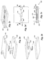
- Microfluidic apparatus 100 in accordance with one embodiment of the invention is shown in Figures 1a-f.
- Microfluidic apparatus 100 includes a platform substrate 102 in which upper and lower microfluidic channels 104 and 106 are formed.
- the upper and lower microfluidic channels are oriented such that the upper channel crosses over the lower channel at a "cross-channel" area 108.
- a porous substrate 110 is disposed between the upper and lower channels proximate to this cross-channel area.
- the porous substrate 110 includes a plurality of pores through which molecular portions of some fluids, including liquids and gases, may pass, while restricting passage of other molecules.
- reservoirs may be connected to one or both ends of the upper channel and/or the lower channel.
- input and output reservoirs 112 and 114 are connected at respective input and output ends of upper channel 104
- input and output reservoirs 116 and 118 are connected at respective input and output ends of lower channel 106.
- the depth of the output reservoirs is extended below the channel depth.
- the platform substrate will comprise an upper and lower half, which are sandwiched around one or more porous membrane/sensors.
- the platform substrate includes an upper substrate member 120 and a lower substrate member 122.
- the upper microfluidic channel 104 is formed in the upper substrate member, while the lower microfluidic channel 106 is formed in the lower substrate.
- lower portions 116B, 118B and 114B of input and output reservoirs 116 and 118 and output reservoir 114, respectively are formed in the lower substrate member, while corresponding through holes 112A, 114A, 116A and 118A are defined in the upper substrate member.
- a recess in which the porous membrane will be disposed upon assembly may be formed in either the upper or lower substrate member.
- a recess 124 is defined in upper substrate member 120.
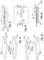
- FIG. 2a-e An embodiment of a single "flow-through" microfluidic apparatus 200 is shown in Figure 2a-e .
- a first reactant fluid enters an input reservoir 212 and flows into upper channel 204.
- a second reactant fluid enters an input/output reservoir 214 and flows into a lower channel 206. Portions of the first and second reactants then pass through the pores in a porous membrane 210 and mix to produce a reaction.
- the porous membrane may change an optical or electrical characteristic, thereby enabling the chemical reaction to be sensed.
- a single fluid is input into input reservoir 212 and flows into upper channel 204.
- a portion of the fluid then passes through porous membrane 210 and into lower channel 206.
- the portion of the fluid passing through the porous membrane may then be collected in input/output reservoir 214.
- the fluid may cause a change in an optical and/or electrical characteristic of the porous membrane in a similar manner to that discussed above.
- microfluidic apparatus 200 comprises a three-part assembly, including an upper substrate member 220, and a lower substrate member 222, which are sandwiched around porous membrane 210.
- a recess may be formed in either the upper or lower substrate member to receive the porous membrane, such as a recess 224 formed in upper substrate member 220.
- microfluidic apparatus 200A having a configuration substantially similar to microfluidic apparatus 200 is shown in Figures 3a-e .
- the primary difference between the two apparatus' is that microfluidic apparatus 200A includes an exit port 230 rather than an input/output reservoir 214. Modifications to accommodate this change are shown in upper and lower substrate members 220A and 222A.
- Microfluidic apparatus 300 in accordance with another embodiment of the invention is shown in Figures 4a-e .
- Microfluidic apparatus 300 includes a plurality of upper channels 304A, 304B, and 304C formed in an upper substrate member 320 and a plurality of lower microfluidic channels 306A, 306B, and 306C formed in a lower substrate member 322.
- a plurality of input reservoirs 312n (a-c) and 316n and output reservoirs 314 n and 318 n may also be provided.
- a plurality of porous membranes 310 are disposed within respective recesses (not shown) in upper substrate member 320 in a manner similar to that described above.
- a single porous membrane 310A may be used, as shown in a microfluidic apparatus 500A shown in Figures 5a-e .
- the single porous membrane may be fabricated to include a plurality of porous sections, such as square or rectangular sections configured in an array (not shown).
- a microfluidic apparatus 600 in accordance with another embodiment of the invention is shown in Figures 6a-e .
- the apparatus includes an upper substrate member 622 in which three upper channels 604A, 604B, and 604C are formed.
- Optional input reservoirs 112 are disposed at the input ends of each of channels 604A-C, while the output ends of the channels meet at an intersection 611.
- the apparatus further includes a lower substrate member 622 in which a single lower microfluidic channel 606 is formed, wherein the lower substrate is similar in configuration with lower substrate member 164 for microfluidic apparatus 150.
- An output reservoir 616 may also be provided to collect fluids exiting the lower microfluidic channel.
- the apparatus further includes a porous membrane 610 disposed within a recess 624 formed in upper substrate member 620, wherein the recess is located proximate to intersection 611.
- Microfluidic apparatus 600 will typically be used in the following manner. Respective fluid reactants will be received at the input ends of the upper microfluidic channels 604 ( e.g., via input reservoirs 612A-C). The fluid reactants will then merge at intersection 611, causing a chemical reaction. A portion of the reactant chemical compound thereby formed will flow into the pores in porous membrane 610, thereby causing a potential change in an optical and/or electrical characteristic of the porous membrane. Such a characteristic change may be measured in the manners described below.
- the porous membrane comprises a porous structure that may be used for filtering, metering, and/or separating chemical and/or biological molecules.
- a porous membrane may be manufactured such that its porosity is greatest along a selected direction.
- the pore sizes can be tuned from a few nanometers to micrometers, thereby enabling the filtration, metering and separation of targeted chemical and biological molecules.
- the porous membranes and porous membrane/sensors may be made from a wide-range of materials in which nano- and micro-porous structures may be formed.
- materials include but are not limited to single crystal porous silicon (PSi), porous polysilicon (PPSi), porous silica, zeolites, photoresists, porous crystals/aggregates, etc.
- the porous membranes will be used for molecular separation and/or molecular (bio)reaction media with built-in real-time detection/monitoring of processes, molecules, fluids, reaction states, etc.
- Porous silicon is a well-characterized material produced through galvanostatic, chemical, or photochemical etching procedures in the presence of HF (hydrofluoric acid) ( A.G. Cullis et al., J. Appl. Phys. 1997, 82, 909 .). Porous silicon can be made generally as complex, anisotropic nanocrystalline structure in silicon layers ( cf ., http://chem-faculty.ucsd.edu/sailor) by either electrochemical etching or stain etching to form porous silicon. The size and orientation of the pores can be controlled by the etching conditions ( e.g., current density, etc.) and substrate type and its electrochemical properties ( R.L. Smith, et al.
- etching conditions e.g., current density, etc.
- substrate type and its electrochemical properties R.L. Smith, et al.
- porous silicon can be formed by spark erosion ( R.E. Hummel, et. al., "On the origin ofphotoluminescence in spark-eroded (porous) silicon,” Appl. Phys. Lett., 1993, 63, 2771 ), resulting in a Si surface with pits and hills of various sizes in the micrometer to nanometers scale.
- Si nanostructures can be produced by an anisotopic etch followed by oxidation ( A.G. Nassiopoulos, et al., "Light emission form silicon nanostructures produced by conventional lithographic and reactive ion etching techniques," Phys. Stat. Sol. (B), 1995,1990, 91 ; S.H.
- porous membrane N 10 e.g., 110, 310, etc.
- porous silicon is etched in a silicon layer of typically ⁇ 0.01-50 ⁇ m thickness either electrochemically or by stain etching to form porous silicon.
- porous polysilicon (PPSi) is deposited by low-pressure chemical vapor deposition (LPCVD), in accordance with a block 702.
- LPCVD low-pressure chemical vapor deposition
- the size and orientation of the pores, porosity, grain size, thickness, etc. may be controlled via appropriate etching conditions (e.g., current density, current duration, etc. ), deposition conditions (e.g., temperature, pressure, etc.), and also substrate type and its electrochemical properties, etc.
- a PSi film (or PPSi film) is physically separated by electropolishing "lift-off" from the PSi-etched or PPSi-deposited silicon and suspended in solution.
- PPSi film may be formed when directly deposited on a substrate (e.g., silicon, quartz, etc.), and can be physically separated by any of various standard etching or micromachining techniques.
- the PSi or PPSi film is then secured within a corresponding recess formed in a substrate half proximate to a cross-channel area in a block 706.
- the substrate may comprise any suitable material in which the microfluidic channels may be formed (e . g ., silicon, quartz, polydimethyl siloxane (PDMS), SU-8 photoresists), and polymers such as polymethylmethacrylate (PMMA), etc. )
- the porous membrane may also be manufactured such that it may be used as a sensor in addition to its filtering/sieving/molecular separation capability.
- the porous membrane may be manufactured to produce a changed optical and/or electrical characteristic in response to being exposed to a targeted fluid or reaction, either through use of the base substrate material (e . g ., PPSi), or through the addition of a sensor layer or through chemical doping and the like.
- PPSi sensor mechanisms may include but are not limited to optical interferometric reflectivity, capacitance modulation, photoluminescence, optical form birefringence, acoustic, etc.
- optical changes may be observed by means of light source 800 and optical detector 802, as shown in Figures 8a-c and 9a-c .
- light source 800 may comprise any device that produces light suitable for detecting a change in a light characteristic of the porous membrane/sensor in combination with corresponding optical detection equipment or devices.
- light source 800 comprises a laser source that produces light at a specific wavelength.
- visible or invisible light may be used.
- visible light wavelengths in one embodiment at least one of the upper and lower substrates is visibly transparent, meaning the substrate(s) produces minimal attenuation of visible light.
- substrate materials are "optically translucent" to these wavelengths, meaning these materials enable light having certain non-visible wavelengths to pass through with minimal attenuation.
- various viewing hole configuration may be defined in substrates that are opaque to light having a wavelength that may be used to detect the change in the optical characteristic of the porous membrane (not shown).
- the optical detector comprises a detector suitable for laser interferometry.
- Other typical optical detector include but are not limited to avalanche photodiodes, various photosensors, and other devices used to measure wavelength, phase shift, and or optical energy/power.
- the optical detector may either include build-in data logging facilities, or external data logging equipment may be connected to the optical detector, such as depicted by a data logger 804.
- a computer 806 with a data-logging card or an electronic instrument interface, such as the GPIB (General Purpose Instrumentation Bus) interface may be used.
- the data logger may store the data locally, or on a computer network, such as in a data store hosted by a database or data system or storage area network (SAN) device.
- SAN storage area network
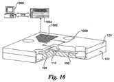
- various electronic instrumentation and/or circuits may be electrically coupled to the porous membrane to sense the changed condition. As discussed above, this may be facilitated by microelectrical traces disposed in the substrate, such as depicted by microelectronic traces 1000 in Figure 10 .
- the substrate may be directly wired to external circuitry and/or electrical equipment, such as via wire bonding and the like.
- signal conditioning and/or test measurement circuitry may be fabricated directly in the platform substrate, as is common in the semiconductor manufacturing arts, as depicted by integrated circuit 1002.
- such signal conditioning and test measurement circuitry may be provided in an electronic measurement device 1006 and/or computer 1006.
- the size of the channels and the cross-channel reactant area occupied by the porous membrane may be adjusted for the various reactants used in the testing.
- the flow of the fluids and molecules can be generated by standard microfluidics methods such as hydrostatic pressure, hydrodynamic, electrokinetic, electroosmotic, hydromagnetic, acoustic and ultrasound, mechanical, electrical field induced, heat-induced and other know methods.
- the flow-through micro-channel configurations (such as shown in Figures 1a-f , 4a-e , and 5a-e ) allow flow-rate control, fluid dilutions, effective wash-out of the channels, minimum back-flow.
- the flow may be blocked for incubations, diffusions, dilutions, etc., using standard microfluidic components and devices.
- the number of inlets and outlets and size of the cross-channel area can be varied based on functional requirements, reactant behaviors, etc.
- massively parallel configurations in accordance with the principles illustrated by the embodiments of Figures 4a-e and 5a-e may be manufactured and employed for testing.
- the porous membrane at each cross channel may have the same or different functionality (optical, biochemical, electrical, acoustic, etc.) as a sensor/detector, molecular separation or sieving filter, bioreactor (with surface modified nanopores, nanopores with immobilized biomolecules, surface coated nanopores, etc.)
Landscapes
- Chemical & Material Sciences (AREA)
- Health & Medical Sciences (AREA)
- Analytical Chemistry (AREA)
- General Health & Medical Sciences (AREA)
- Hematology (AREA)
- Clinical Laboratory Science (AREA)
- Chemical Kinetics & Catalysis (AREA)
- Dispersion Chemistry (AREA)
- Life Sciences & Earth Sciences (AREA)
- Molecular Biology (AREA)
- Investigating Or Analysing Materials By Optical Means (AREA)
- Automatic Analysis And Handling Materials Therefor (AREA)
- Apparatus Associated With Microorganisms And Enzymes (AREA)
- Separation Using Semi-Permeable Membranes (AREA)
- Physical Or Chemical Processes And Apparatus (AREA)
- Investigating Or Analysing Biological Materials (AREA)
- Micromachines (AREA)
Claims (25)
- Appareil (100) comportant :un substrat (102) dans lequel sont définis :un canal microfluidique supérieur (104) traversant le substrat suivant une première direction ;un canal microfluidique inférieur (106), traversant le substrat suivant une deuxième direction, une partie du canal microfluidique inférieur passant sous une partie du canal microfluidique supérieur pour former une zone (108) de croisement de canaux ; etune membrane poreuse (110) disposée entre les canaux microfluidiques supérieur et inférieur à proximité de la zone de croisement de canaux pour former une barrière semi-perméable entre les canaux microfluidiques supérieur et inférieur,la membrane poreuse (110) comportant soit du silicium nanocristallin poreux, soit du polysilicium poreux.
- Appareil selon la revendication 1, comportant en outre un premier réservoir défini dans le substrat et relié en communication fluidique avec un des canaux microfluidiques supérieur et inférieur.
- Appareil selon la revendication 2, comportant en outre un deuxième réservoir défini dans le substrat et relié en communication fluidique avec l'autre des canaux microfluidiques supérieur et inférieur qui n'est pas relié en communication fluidique avec le premier réservoir.
- Appareil selon la revendication 1, comportant en outre des réservoirs respectifs définis dans le substrat à des extrémités opposées d'au moins un des canaux microfluidiques supérieur et inférieur.
- Appareil selon la revendication 1, la membrane poreuse présentant une caractéristique de détection, telle qu'une réflectivité interférométrique optique, une modulation de capacitance, une photoluminescence, une biréfringence optique de forme ou des propriétés acoustiques, qui provoque un changement d'au moins une caractéristique parmi des caractéristiques optique et électrique en réaction à une exposition à un ou plusieurs solutés et/ou analytes particuliers.
- Appareil selon la revendication 5, la caractéristique de détection comportant un changement d'une caractéristique optique, et l'appareil comportant en outre :une source lumineuse servant à diriger une lumière vers la membrane poreuse ; etun détecteur, servant à recevoir une partie de la lumière réfléchie sur et/ou émise par la membrane poreuse en silicium pour détecter le changement de la caractéristique optique de la membrane poreuse.
- Appareil selon la revendication 6, comportant en outre un équipement de recueil de données lié en communication avec le détecteur pour recueillir des données se rapportant à des changements de la caractéristique optique de la membrane poreuse.
- Appareil selon la revendication 5, la caractéristique de détection comportant une caractéristique électrique et le substrat comprenant en outre des tracés microélectroniques reliés fonctionnellement à la membrane poreuse.
- Appareil selon la revendication 8, comprenant en outre un dispositif électronique de mesure, couplé à la membrane poreuse via les tracés microélectroniques, pour mesurer un changement d'une caractéristique électrique de la membrane poreuse en silicium lorsqu'elle est exposée audit ou auxdits fluides particuliers.
- Appareil selon la revendication 9, comportant en outre un équipement de recueil de données relié en communication avec le dispositif électronique de mesure.
- Appareil selon la revendication 1, la membrane poreuse présentant une épaisseur médiane variant entre environ 10 nanomètres et environ 50 micromètres.
- Appareil selon la revendication 1, la membrane poreuse présentant une pluralité de pores présentant un diamètre médian variant entre environ 50 angströms et environ 10 micromètres.
- Appareil selon la revendication 1, le substrat étant constitué d'un substrat en polydiméthyl siloxane (PDMS), en silicium, en quartz, en polymère ou en polyméthylméthacrylate (PMMA).
- Appareil selon la revendication 1, le substrat comportant un élément supérieur de substrat dans lequel est formé le canal microfluidique supérieur et un élément inférieur de substrat dans lequel est formé le canal microfluidique inférieur, lesdits éléments supérieur et inférieur de substrat étant placés en sandwich autour du substrat poreux suite à l'assemblage.
- Appareil selon la revendication 1,
le substrat (105) dans lequel sont en outre définis :le canal microfluidique supérieur (104) comprenant une pluralité de canaux microfluidiques supérieurs (304A, 304B, 304C) ;le canal microfluidique inférieur (106) comprenant au moins un canal microfluidique inférieur (306A, 306B, 306C) ;la partie du canal microfluidique inférieur (106) comprenant des parties respectives dudit ou desdits canaux microfluidiques inférieurs passant sous la partie du canal microfluidique supérieur (104) comprenant des parties respectives de la pluralité de canaux microfluidiques supérieurs ;la zone (108) de croisement de canaux comprenant une pluralité de zones respectives de croisement de canaux ;la membrane poreuse (110) comprenant au moins une membrane poreuse (310). - Appareil selon la revendication 15, ledit ou lesdits canaux microfluidiques inférieurs comportant une pluralité de canaux, et la pluralité de zones de croisement de canaux étant sensiblement configurée en une matrice.
- Appareil selon la revendication 15, ladite ou lesdites membranes poreuses comportant une pluralité de membrane poreuses, dont chacune est respectivement disposée à proximité d'une zone respective de croisement de canaux.
- Appareil selon la revendication 15, le substrat comportant un élément supérieur de substrat dans lequel est formée la pluralité de canaux microfluidiques supérieurs et un élément inférieur de substrat dans lequel sont formés ledit ou lesdits canaux microfluidiques inférieurs, lesdits éléments supérieur et inférieur de substrat étant placés en sandwich autour dudit ou desdits substrat en silicium poreux suite à l'assemblage.
- Appareil selon la revendication 15, la membrane poreuse en silicium présentant une caractéristique de détection, telle qu'une réflectivité interférométrique optique, une modulation de capacitance, une photoluminescence, une biréfringence optique de forme ou des propriétés acoustiques, qui provoque un changement d'au moins une caractéristique parmi des caractéristiques optique et électrique en réaction à une exposition à un ou plusieurs solutés et/ou analytes particuliers.
- Appareil selon la revendication 19, la caractéristique de détection comportant un changement d'une caractéristique optique, et l'appareil comporte en outre :une source lumineuse servant à diriger une lumière vers la membrane poreuse ; etun détecteur, servant à recevoir une partie de la lumière réfléchie sur et/ou émise par la membrane poreuse en silicium pour détecter le changement de la caractéristique optique de la membrane poreuse.
- Appareil selon la revendication 19, la caractéristique de détection comportant une caractéristique électrique, et le substrat comprenant en outre des tracés microélectroniques reliés fonctionnellement à la membrane poreuse.
- Appareil selon la revendication 1,
le substrat (102) dans lequel sont en outre définis :le canal microfluidique supérieur (104) comprenant une pluralité de canaux microfluidiques supérieurs (604A, 604B, 604C), chaque canal de la pluralité de canaux microfluidiques supérieurs (604A, 604B, 604C) présentant une première extrémité et une deuxième extrémité, lesdites deuxièmes extrémités fusionnant ensemble à une intersection (611) ;la partie du canal microfluidique supérieur (104) étant l'intersection (611) ;la partie du canal microfluidique inférieur (606) étant une première extrémité de celui-ci. - Appareil selon la revendication 22, comportant en outre une pluralité de réservoirs disposés dans le substrat, dont chacun est respectivement disposé à une première extrémité d'un canal microfluidique supérieur respectif.
- Appareil selon la revendication 23, le substrat comportant un élément supérieur de substrat dans lequel est formée la pluralité de canaux microfluidiques supérieurs et un élément inférieur de substrat dans lequel est formé le canal microfluidique inférieur, lesdits éléments supérieur et inférieur de substrat étant placés en sandwich autour du substrat en silicium poreux suite à l'assemblage.
- Appareil selon la revendication 22; la membrane poreuse présentant une caractéristique de détection, telle qu'une réflectivité interférométrique optique, une modulation de capacitance, une photoluminescence, une biréfringence optique de forme ou des propriétés acoustiques, qui provoque un changement d'au moins une caractéristique parmi des caractéristiques optique et électrique en réaction à une exposition à un ou plusieurs solutés et/ou analytes particuliers.
Applications Claiming Priority (3)
| Application Number | Priority Date | Filing Date | Title |
|---|---|---|---|
| US243089 | 2002-09-12 | ||
| US10/243,089 US6806543B2 (en) | 2002-09-12 | 2002-09-12 | Microfluidic apparatus with integrated porous-substrate/sensor for real-time (bio)chemical molecule detection |
| PCT/US2003/028086 WO2004024327A1 (fr) | 2002-09-12 | 2003-09-05 | Appareil microfluidique comprenant des capteurs a substrat poreux integres destine a la detection de molecules et composes biologiques et chimiques en temps reel |
Publications (2)
| Publication Number | Publication Date |
|---|---|
| EP1542802A1 EP1542802A1 (fr) | 2005-06-22 |
| EP1542802B1 true EP1542802B1 (fr) | 2016-10-26 |
Family
ID=31991547
Family Applications (1)
| Application Number | Title | Priority Date | Filing Date |
|---|---|---|---|
| EP03770294.1A Expired - Lifetime EP1542802B1 (fr) | 2002-09-12 | 2003-09-05 | Appareil microfluidique comprenant des capteurs a substrat poreux integres destine a la detection de molecules et composes biologiques et chimiques en temps reel |
Country Status (7)
| Country | Link |
|---|---|
| US (3) | US6806543B2 (fr) |
| EP (1) | EP1542802B1 (fr) |
| JP (1) | JP4353900B2 (fr) |
| CN (1) | CN100348323C (fr) |
| AU (1) | AU2003278774A1 (fr) |
| TW (1) | TWI249433B (fr) |
| WO (1) | WO2004024327A1 (fr) |
Cited By (1)
| Publication number | Priority date | Publication date | Assignee | Title |
|---|---|---|---|---|
| US9487812B2 (en) | 2012-02-17 | 2016-11-08 | Colorado School Of Mines | Optical alignment deformation spectroscopy |
Families Citing this family (101)
| Publication number | Priority date | Publication date | Assignee | Title |
|---|---|---|---|---|
| US7485454B1 (en) | 2000-03-10 | 2009-02-03 | Bioprocessors Corp. | Microreactor |
| US6913697B2 (en) | 2001-02-14 | 2005-07-05 | Science & Technology Corporation @ Unm | Nanostructured separation and analysis devices for biological membranes |
| CA2440785A1 (fr) * | 2001-04-10 | 2002-10-24 | Bioprocessors Corporation | Microdispositif de fermentation et procede de criblage a base de cellules |
| WO2003015890A1 (fr) * | 2001-08-20 | 2003-02-27 | President And Fellows Of Harvard College | Jeux ordonnes d'echantillons fluides et procede d'utilisation |
| WO2003047712A2 (fr) * | 2001-10-18 | 2003-06-12 | The Board Of Trustees Of The University Of Illinois | Systeme hybride microfluidique et nanofluidique |
| WO2003066191A1 (fr) | 2002-02-04 | 2003-08-14 | Colorado School Of Mines | Separations de particules cellulaires et colloidales par ecoulements laminaires |
| US7361313B2 (en) * | 2003-02-18 | 2008-04-22 | Intel Corporation | Methods for uniform metal impregnation into a nanoporous material |
| US6806543B2 (en) | 2002-09-12 | 2004-10-19 | Intel Corporation | Microfluidic apparatus with integrated porous-substrate/sensor for real-time (bio)chemical molecule detection |
| US7279134B2 (en) * | 2002-09-17 | 2007-10-09 | Intel Corporation | Microfluidic devices with porous membranes for molecular sieving, metering, and separations |
| EP2359689B1 (fr) | 2002-09-27 | 2015-08-26 | The General Hospital Corporation | Dispositif microfluidique pour la séparation de cellules et usage du dispositif |
| WO2004071949A2 (fr) * | 2003-02-13 | 2004-08-26 | The Regents Of The University Of California | Moulage nanostructure de polymeres organiques et de biopolymeres dans des matrices de silicium poreux |
| US7347921B2 (en) * | 2003-07-17 | 2008-03-25 | Agilent Technologies, Inc. | Apparatus and method for threading a biopolymer through a nanopore |
| US20050148064A1 (en) * | 2003-12-29 | 2005-07-07 | Intel Corporation | Microfluid molecular-flow fractionator and bioreactor with integrated active/passive diffusion barrier |
| JP2007525667A (ja) * | 2004-02-17 | 2007-09-06 | ヘンケル カーゲーアーアー | マイクロ流体分析用デバイス |
| US20050221473A1 (en) * | 2004-03-30 | 2005-10-06 | Intel Corporation | Sensor array integrated circuits |
| WO2005111435A2 (fr) * | 2004-05-10 | 2005-11-24 | The Aerospace Corporation | Dispositifs microfluidiques a modules support de fluide et a actionnement separable |
| WO2006025014A1 (fr) * | 2004-09-03 | 2006-03-09 | Koninklijke Philips Electronics N. V. | Systeme microfluidique |
| WO2006027738A1 (fr) * | 2004-09-10 | 2006-03-16 | Philips Intellectual Property & Standards Gmbh | Composes et procedes pour combinaison imagerie optique-imagerie par ultrasons |
| EP1814666A2 (fr) | 2004-11-16 | 2007-08-08 | Koninklijke Philips Electronics N.V. | Dispositif microfluidique |
| KR100635110B1 (ko) * | 2004-12-09 | 2006-10-17 | 주식회사 바이오디지트 | 현장분석용 랩온어칩 및 랩온어칩용 신호탐지기 |
| WO2006065806A2 (fr) | 2004-12-14 | 2006-06-22 | The Regents Of The University Of California | Particules photoniques en polymere composite |
| US20070196820A1 (en) | 2005-04-05 | 2007-08-23 | Ravi Kapur | Devices and methods for enrichment and alteration of cells and other particles |
| EP1888213B1 (fr) | 2005-05-25 | 2017-10-18 | Bio-Rad Laboratories, Inc. | Dispositif fluidique |
| US7947485B2 (en) * | 2005-06-03 | 2011-05-24 | Hewlett-Packard Development Company, L.P. | Method and apparatus for molecular analysis using nanoelectronic circuits |
| US20060275779A1 (en) * | 2005-06-03 | 2006-12-07 | Zhiyong Li | Method and apparatus for molecular analysis using nanowires |
| US8921102B2 (en) | 2005-07-29 | 2014-12-30 | Gpb Scientific, Llc | Devices and methods for enrichment and alteration of circulating tumor cells and other particles |
| WO2007039852A1 (fr) * | 2005-10-03 | 2007-04-12 | Koninklijke Philips Electronics N.V. | Biocapteurs a sensibilite amelioree |
| KR100697292B1 (ko) * | 2005-10-04 | 2007-03-20 | 삼성전자주식회사 | 반도체 장치 및 그 형성 방법 |
| EP1960105A1 (fr) * | 2005-11-25 | 2008-08-27 | Koninklijke Philips Electronics N.V. | Dispositif microfluidique a membrane poreuse et canal non raccorde |
| US9878326B2 (en) | 2007-09-26 | 2018-01-30 | Colorado School Of Mines | Fiber-focused diode-bar optical trapping for microfluidic manipulation |
| US8119976B2 (en) | 2007-07-03 | 2012-02-21 | Colorado School Of Mines | Optical-based cell deformability |
| US9885644B2 (en) | 2006-01-10 | 2018-02-06 | Colorado School Of Mines | Dynamic viscoelasticity as a rapid single-cell biomarker |
| CN101416048B (zh) * | 2006-01-12 | 2013-10-02 | 迈克罗拉布诊断有限公司 | 新仪器系统和方法 |
| JP5946235B2 (ja) * | 2006-03-29 | 2016-07-06 | ダウ コーニング コーポレーションDow Corning Corporation | ソフトリソグラフィーを使用するナノスケールの特徴形体の生成方法 |
| JP2008051803A (ja) * | 2006-07-28 | 2008-03-06 | Sharp Corp | 分析用マイクロ流路デバイス |
| US7516658B2 (en) | 2006-09-29 | 2009-04-14 | Rosemount Inc. | Electro-kinetic pressure/flow sensor |
| US9538657B2 (en) | 2012-06-29 | 2017-01-03 | General Electric Company | Resonant sensor and an associated sensing method |
| US9589686B2 (en) * | 2006-11-16 | 2017-03-07 | General Electric Company | Apparatus for detecting contaminants in a liquid and a system for use thereof |
| US10914698B2 (en) | 2006-11-16 | 2021-02-09 | General Electric Company | Sensing method and system |
| US9658178B2 (en) | 2012-09-28 | 2017-05-23 | General Electric Company | Sensor systems for measuring an interface level in a multi-phase fluid composition |
| US9536122B2 (en) | 2014-11-04 | 2017-01-03 | General Electric Company | Disposable multivariable sensing devices having radio frequency based sensors |
| US7748283B2 (en) * | 2007-02-16 | 2010-07-06 | Whatman, Inc. | Controlled transfer biological sample collection devices and methods of using such devices |
| US20080317633A1 (en) * | 2007-04-30 | 2008-12-25 | Stc.Unm | Multiplex lateral flow devices and methods |
| US10722250B2 (en) | 2007-09-04 | 2020-07-28 | Colorado School Of Mines | Magnetic-field driven colloidal microbots, methods for forming and using the same |
| CN101530775B (zh) * | 2009-03-03 | 2011-06-15 | 南京大学 | 一种集成pdms薄膜的微流控器件及其制法和用途 |
| US8926904B2 (en) * | 2009-05-12 | 2015-01-06 | Daniel Wai-Cheong So | Method and apparatus for the analysis and identification of molecules |
| US20170356038A1 (en) * | 2009-05-12 | 2017-12-14 | Daniel Wai-Cheong So | Method and apparatus for the analysis and identification of molecules |
| US20120171087A1 (en) * | 2009-10-02 | 2012-07-05 | Simpore, Inc. | Methods for Facilitating Fluid Flow Through Nanoporous Membranes |
| US8778690B2 (en) | 2010-08-31 | 2014-07-15 | The Regents Of The University Of California | Porous optical sensor with fiducial marker and method for detection of analytes |
| WO2012042226A2 (fr) * | 2010-10-01 | 2012-04-05 | Oxford Nanopore Technologies Limited | Appareil d'analyse biochimique et vanne rotative |
| US9012255B1 (en) * | 2010-10-27 | 2015-04-21 | Dunan Microstaq, Inc. | MEMS package |
| US8542023B2 (en) | 2010-11-09 | 2013-09-24 | General Electric Company | Highly selective chemical and biological sensors |
| TWI448689B (zh) * | 2010-11-26 | 2014-08-11 | Univ Ishou | Micro-detection device |
| DE102011003856B4 (de) | 2011-02-09 | 2020-06-18 | Robert Bosch Gmbh | Mikrosystem für fluidische Anwendungen sowie Herstellungsverfahren und Benutzungsverfahren für ein Mikrosystem für fluidische Anwendungen |
| FR2972117B1 (fr) * | 2011-03-04 | 2013-12-20 | Centre Nat Rech Scient | Systeme microfluidique pour controler un profil de concentration de molecules susceptibles de stimuler une cible |
| US9469871B2 (en) | 2011-04-14 | 2016-10-18 | Corporos Inc. | Methods and apparatus for point-of-care nucleic acid amplification and detection |
| DE102011076693A1 (de) * | 2011-05-30 | 2012-12-06 | Robert Bosch Gmbh | Mikrofluidische Vorrichtung mit elektronischem Bauteil und Federelement |
| US8717556B2 (en) * | 2011-07-27 | 2014-05-06 | Aptina Imaging Corporation | Microfluidic systems with chemical pumps |
| JP5807542B2 (ja) | 2011-12-22 | 2015-11-10 | 株式会社島津製作所 | 対象成分を操作するためのチップデバイス及びそれを用いた方法 |
| US8925793B2 (en) | 2012-01-05 | 2015-01-06 | Dunan Microstaq, Inc. | Method for making a solder joint |
| KR101319771B1 (ko) | 2012-04-05 | 2013-10-17 | 공주대학교 산학협력단 | 박막 면의 광학적 특성 변화를 이용한 다기능 측정 장치와 그곳에 사용될 수 있는 감지막 및 그 제조방법 |
| US10145842B2 (en) | 2012-04-11 | 2018-12-04 | Quidel Cardiovascular Inc. | Microfluidic device, system and method |
| US9354159B2 (en) | 2012-05-02 | 2016-05-31 | Nanoscopia (Cayman), Inc. | Opto-fluidic system with coated fluid channels |
| US10265452B2 (en) | 2012-05-16 | 2019-04-23 | The Regents Of The University Of California | Low resistance microfabricated filter |
| US10598650B2 (en) | 2012-08-22 | 2020-03-24 | General Electric Company | System and method for measuring an operative condition of a machine |
| DE112013004129T5 (de) | 2012-08-22 | 2015-05-21 | General Electric Company | Drahtloses System und Verfahren zum Messen einer Betriebsbedingung einer Maschine |
| US10684268B2 (en) | 2012-09-28 | 2020-06-16 | Bl Technologies, Inc. | Sensor systems for measuring an interface level in a multi-phase fluid composition |
| KR20140068758A (ko) * | 2012-11-28 | 2014-06-09 | 서울대학교산학협력단 | 미세 유체칩을 이용한 나노입자 분리 및 이를 이용한 생체물질분석방법 |
| US9386948B2 (en) | 2012-12-05 | 2016-07-12 | Theranos, Inc. | Systems, devices, and methods for bodily fluid sample transport |
| US10248765B1 (en) | 2012-12-05 | 2019-04-02 | Theranos Ip Company, Llc | Systems, devices, and methods for bodily fluid sample collection, transport, and handling |
| TWI512286B (zh) * | 2013-01-08 | 2015-12-11 | Univ Nat Yunlin Sci & Tech | 微流體生醫感測系統 |
| EP2972184A4 (fr) | 2013-03-15 | 2016-11-30 | Theranos Inc | Procédés et dispositifs pour collecte d'échantillons et séparation d'échantillons |
| US9347962B2 (en) | 2013-08-05 | 2016-05-24 | Nanoscopia (Cayman), Inc. | Handheld diagnostic system with chip-scale microscope and automated image capture mechanism |
| FR3012982B1 (fr) * | 2013-11-08 | 2015-12-25 | Espci Innov | Procede de stockage et de concentration d'un compose volatil |
| CN113796860A (zh) * | 2014-03-05 | 2021-12-17 | 赛拉诺斯知识产权有限责任公司 | 用于样品收集和样品分离的方法和装置 |
| DK2923754T3 (da) * | 2014-03-26 | 2019-11-11 | Corning Inc | Modulært, fotokemisk strømningsreaktoranlæg |
| JP6258144B2 (ja) * | 2014-07-18 | 2018-01-10 | 株式会社東芝 | 半導体マイクロ分析チップ |
| JP6258145B2 (ja) | 2014-07-18 | 2018-01-10 | 株式会社東芝 | 微粒子検査システム及びその駆動方法 |
| KR102587637B1 (ko) * | 2014-12-12 | 2023-10-10 | 옵코 다이어그노스틱스, 엘엘씨 | 성형에 의해 제조되는 유체 시스템을 비롯한, 항온 처리 채널을 포함하는 유체 시스템 |
| HK1250784A1 (zh) * | 2015-04-09 | 2019-01-11 | Angle Europe Limited | 一次性生物测定盒及盒内执行多个测定步骤和流体输送的方法 |
| TWI581862B (zh) * | 2015-06-16 | 2017-05-11 | 亞諾法生技股份有限公司 | 微流道裝置的夾持載具 |
| CN105129722B (zh) * | 2015-07-01 | 2017-03-01 | 北京工业大学 | 单面微米级薄膜微通道的制作方法 |
| US10371606B2 (en) | 2015-07-21 | 2019-08-06 | Theraos IP Company, LLC | Bodily fluid sample collection and transport |
| WO2017044888A1 (fr) | 2015-09-09 | 2017-03-16 | Theranos, Inc. | Procédés et dispositifs de collecte et de séparation d'échantillons |
| WO2017044732A1 (fr) | 2015-09-09 | 2017-03-16 | Northwestern University | Dispositifs, systèmes, et procédés de préparation de spécimens faisant appel à des forces capillaires et centrifuges |
| CN105536898B (zh) * | 2015-12-14 | 2017-07-07 | 清华大学 | 微流控芯片、血细胞分离方法与系统及该系统的制作方法 |
| KR102205435B1 (ko) * | 2016-03-21 | 2021-01-21 | 온테라 인크. | 나노기공 감지를 위한 절연체-막-절연체 장치의 웨이퍼-척도 어셈블리 |
| CN107290277A (zh) * | 2016-03-31 | 2017-10-24 | 光合声科技股份有限公司 | 光学式生物传感器与微流体装置的整合结构 |
| CN105970278A (zh) * | 2016-04-27 | 2016-09-28 | 杭州芬得检测技术有限公司 | 多孔硅材料的制配方法 |
| WO2018022014A1 (fr) * | 2016-07-26 | 2018-02-01 | Hewlett-Packard Development Company, L.P. | Dispositif microfluidique avec collecteur |
| KR102446129B1 (ko) | 2016-10-03 | 2022-09-22 | 젠비다 테크놀로지 컴퍼니 리미티드 | 분자의 식별 및 분석을 위한 장치 및 방법. |
| CN110099744A (zh) * | 2017-02-22 | 2019-08-06 | 阿尔卑斯阿尔派株式会社 | 流路芯片及流路芯片的制造方法 |
| US11857966B1 (en) | 2017-03-15 | 2024-01-02 | Labrador Diagnostics Llc | Methods and devices for sample collection and sample separation |
| CN107478851A (zh) * | 2017-08-23 | 2017-12-15 | 成都和合医学检验所有限公司 | 快速定量检测人体血液中25‑羟基维生素d3含量的方法 |
| CN112512656A (zh) * | 2018-05-30 | 2021-03-16 | 加利福尼亚大学董事会 | 用于组织和细胞聚集体解离及单细胞富集的微流体过滤装置及方法 |
| US11964237B2 (en) * | 2018-11-16 | 2024-04-23 | Integrated Protein Technologies, Inc. | Molecular weight filtration system and apparatus with additional flow configurations |
| US10864483B2 (en) * | 2018-11-16 | 2020-12-15 | Integrated Protein Technologies, Snc. | Molecular weight filtration system and apparatus |
| US11850556B2 (en) * | 2018-11-16 | 2023-12-26 | Integrated Protein Technologies, Inc. | Frit for use with molecular weight filtration system and apparatus |
| CN110013891B (zh) * | 2019-01-24 | 2020-09-25 | 厦门大学 | 一种基于仿生响应性液体门控的微流控系统及控制方法 |
| CN110479391B (zh) * | 2019-08-05 | 2021-09-24 | 湖北医药学院 | 一种基于固态径迹刻蚀纳米孔的低电压高性能电渗微泵芯片 |
| US12134095B2 (en) * | 2022-01-24 | 2024-11-05 | Siphox, Inc. | Apparatus and methods for performing microfluidic-based biochemical assays |
Citations (1)
| Publication number | Priority date | Publication date | Assignee | Title |
|---|---|---|---|---|
| WO2004024300A1 (fr) * | 2002-09-11 | 2004-03-25 | The Regents Of The University Of Michigan | Membrane d'ultrafiltration, dispositif, organe bioartificiel et procedes associes |
Family Cites Families (27)
| Publication number | Priority date | Publication date | Assignee | Title |
|---|---|---|---|---|
| ATE214633T1 (de) | 1993-10-28 | 2002-04-15 | Houston Advanced Res Ct | Mikrofabriziertes poröses durchflussgerät |
| US5623598A (en) * | 1994-11-22 | 1997-04-22 | Hewlett-Packard Company | Method for identifying ways to improve performance in computer data storage systems |
| US5919364A (en) | 1996-06-24 | 1999-07-06 | Regents Of The University Of California | Microfabricated filter and shell constructed with a permeable membrane |
| US6074827A (en) * | 1996-07-30 | 2000-06-13 | Aclara Biosciences, Inc. | Microfluidic method for nucleic acid purification and processing |
| US5961932A (en) * | 1997-06-20 | 1999-10-05 | Eastman Kodak Company | Reaction chamber for an integrated micro-ceramic chemical plant |
| US6293012B1 (en) * | 1997-07-21 | 2001-09-25 | Ysi Incorporated | Method of making a fluid flow module |
| US6248539B1 (en) * | 1997-09-05 | 2001-06-19 | The Scripps Research Institute | Porous semiconductor-based optical interferometric sensor |
| AU1517999A (en) | 1997-10-15 | 1999-05-03 | Aclara Biosciences, Inc. | Laminate microstructure device and method for making same |
| US6035306A (en) * | 1997-11-24 | 2000-03-07 | Terascape Software Inc. | Method for improving performance of large databases |
| US6117643A (en) * | 1997-11-25 | 2000-09-12 | Ut Battelle, Llc | Bioluminescent bioreporter integrated circuit |
| US6167910B1 (en) * | 1998-01-20 | 2001-01-02 | Caliper Technologies Corp. | Multi-layer microfluidic devices |
| DE19822199C2 (de) * | 1998-05-16 | 2003-02-13 | Wella Ag | Mono- oder Polymethinfarbstoffe enthaltende nicht-oxidative Haarfärbemittel und Verfahren zur temporären Haarfärbung |
| US6149787A (en) * | 1998-10-14 | 2000-11-21 | Caliper Technologies Corp. | External material accession systems and methods |
| EP1309404A2 (fr) | 2000-08-07 | 2003-05-14 | Nanostream, Inc. | Melangeur fluidique pour systeme microfluidique |
| EP1343973B2 (fr) * | 2000-11-16 | 2020-09-16 | California Institute Of Technology | Appareil et procedes pour effectuer des dosages et des criblages a haut rendement |
| JP2002218974A (ja) | 2001-01-24 | 2002-08-06 | Ebara Corp | 反応プローブチップ及び検出システム |
| US6418968B1 (en) | 2001-04-20 | 2002-07-16 | Nanostream, Inc. | Porous microfluidic valves |
| WO2003015890A1 (fr) * | 2001-08-20 | 2003-02-27 | President And Fellows Of Harvard College | Jeux ordonnes d'echantillons fluides et procede d'utilisation |
| US20030094369A1 (en) * | 2001-10-01 | 2003-05-22 | Brigham Young University | Method of simultaneously concentrating and separating analytes |
| WO2003047712A2 (fr) * | 2001-10-18 | 2003-06-12 | The Board Of Trustees Of The University Of Illinois | Systeme hybride microfluidique et nanofluidique |
| US20030104512A1 (en) * | 2001-11-30 | 2003-06-05 | Freeman Alex R. | Biosensors for single cell and multi cell analysis |
| DE10202094B4 (de) * | 2002-01-21 | 2006-09-28 | Eppendorf Ag | Verfahren und Vorrichtung zur Elektroporation biologischer Zellen |
| US20030180711A1 (en) * | 2002-02-21 | 2003-09-25 | Turner Stephen W. | Three dimensional microfluidic device having porous membrane |
| US6806543B2 (en) * | 2002-09-12 | 2004-10-19 | Intel Corporation | Microfluidic apparatus with integrated porous-substrate/sensor for real-time (bio)chemical molecule detection |
| US7279134B2 (en) * | 2002-09-17 | 2007-10-09 | Intel Corporation | Microfluidic devices with porous membranes for molecular sieving, metering, and separations |
| US20050129580A1 (en) * | 2003-02-26 | 2005-06-16 | Swinehart Philip R. | Microfluidic chemical reactor for the manufacture of chemically-produced nanoparticles |
| US7347921B2 (en) * | 2003-07-17 | 2008-03-25 | Agilent Technologies, Inc. | Apparatus and method for threading a biopolymer through a nanopore |
-
2002
- 2002-09-12 US US10/243,089 patent/US6806543B2/en not_active Expired - Lifetime
-
2003
- 2003-08-19 TW TW92122752A patent/TWI249433B/zh not_active IP Right Cessation
- 2003-09-05 JP JP2004536149A patent/JP4353900B2/ja not_active Expired - Fee Related
- 2003-09-05 AU AU2003278774A patent/AU2003278774A1/en not_active Abandoned
- 2003-09-05 EP EP03770294.1A patent/EP1542802B1/fr not_active Expired - Lifetime
- 2003-09-05 WO PCT/US2003/028086 patent/WO2004024327A1/fr not_active Ceased
- 2003-09-05 CN CNB038209217A patent/CN100348323C/zh not_active Expired - Fee Related
-
2004
- 2004-05-27 US US10/856,372 patent/US8153079B2/en not_active Expired - Fee Related
-
2011
- 2011-10-13 US US13/272,858 patent/US8465698B2/en not_active Expired - Fee Related
Patent Citations (1)
| Publication number | Priority date | Publication date | Assignee | Title |
|---|---|---|---|---|
| WO2004024300A1 (fr) * | 2002-09-11 | 2004-03-25 | The Regents Of The University Of Michigan | Membrane d'ultrafiltration, dispositif, organe bioartificiel et procedes associes |
Cited By (1)
| Publication number | Priority date | Publication date | Assignee | Title |
|---|---|---|---|---|
| US9487812B2 (en) | 2012-02-17 | 2016-11-08 | Colorado School Of Mines | Optical alignment deformation spectroscopy |
Also Published As
| Publication number | Publication date |
|---|---|
| JP4353900B2 (ja) | 2009-10-28 |
| AU2003278774A1 (en) | 2004-04-30 |
| US20040051154A1 (en) | 2004-03-18 |
| HK1084067A1 (en) | 2006-07-21 |
| WO2004024327A1 (fr) | 2004-03-25 |
| US20040219072A1 (en) | 2004-11-04 |
| US6806543B2 (en) | 2004-10-19 |
| US20120141329A1 (en) | 2012-06-07 |
| JP2005539222A (ja) | 2005-12-22 |
| TW200414928A (en) | 2004-08-16 |
| CN100348323C (zh) | 2007-11-14 |
| TWI249433B (en) | 2006-02-21 |
| CN1678398A (zh) | 2005-10-05 |
| EP1542802A1 (fr) | 2005-06-22 |
| US8465698B2 (en) | 2013-06-18 |
| US8153079B2 (en) | 2012-04-10 |
Similar Documents
| Publication | Publication Date | Title |
|---|---|---|
| EP1542802B1 (fr) | Appareil microfluidique comprenant des capteurs a substrat poreux integres destine a la detection de molecules et composes biologiques et chimiques en temps reel | |
| US20050148064A1 (en) | Microfluid molecular-flow fractionator and bioreactor with integrated active/passive diffusion barrier | |
| US7279134B2 (en) | Microfluidic devices with porous membranes for molecular sieving, metering, and separations | |
| CA2518477C (fr) | Separateur microfluidique | |
| US5716852A (en) | Microfabricated diffusion-based chemical sensor | |
| US8262909B2 (en) | Methods and devices for minimizing membrane fouling for microfluidic separators | |
| US6742661B1 (en) | Well-plate microfluidics | |
| US5644395A (en) | Miniaturized flow injection analysis system | |
| EP2227329B1 (fr) | Dispositif microfluidique, son procédé de fabrication et capteur l'incorporant | |
| EP1058939A4 (fr) | Dispositifs et systemes microfluidiques a elements optiques integres | |
| EP1392436B1 (fr) | Collecteurs de fractions microfluidiques | |
| Madou et al. | A novel design on a CD disc for 2-point calibration measurement | |
| KR20050065895A (ko) | 생체분자 필터 및 그 제조방법 | |
| HK1084067B (en) | Microfluidic apparatus with integrated porous-substrates/sensor for real-time(bio) chemical molecule detection | |
| Shen et al. | Micromachined nanofiltration modules for lab-on-a-chip applications | |
| Wong | Microfluidic device, and related methods | |
| HK1084068A (en) | Microfluidic devices with porous membranes for molecular sieving, metering, and separations |
Legal Events
| Date | Code | Title | Description |
|---|---|---|---|
| PUAI | Public reference made under article 153(3) epc to a published international application that has entered the european phase |
Free format text: ORIGINAL CODE: 0009012 |
|
| 17P | Request for examination filed |
Effective date: 20050412 |
|
| AK | Designated contracting states |
Kind code of ref document: A1 Designated state(s): AT BE BG CH CY CZ DE DK EE ES FI FR GB GR HU IE IT LI LU MC NL PT RO SE SI SK TR |
|
| AX | Request for extension of the european patent |
Extension state: AL LT LV MK |
|
| DAX | Request for extension of the european patent (deleted) | ||
| 17Q | First examination report despatched |
Effective date: 20061214 |
|
| GRAP | Despatch of communication of intention to grant a patent |
Free format text: ORIGINAL CODE: EPIDOSNIGR1 |
|
| INTG | Intention to grant announced |
Effective date: 20160512 |
|
| GRAS | Grant fee paid |
Free format text: ORIGINAL CODE: EPIDOSNIGR3 |
|
| GRAA | (expected) grant |
Free format text: ORIGINAL CODE: 0009210 |
|
| AK | Designated contracting states |
Kind code of ref document: B1 Designated state(s): AT BE BG CH CY CZ DE DK EE ES FI FR GB GR HU IE IT LI LU MC NL PT RO SE SI SK TR |
|
| REG | Reference to a national code |
Ref country code: GB Ref legal event code: FG4D |
|
| REG | Reference to a national code |
Ref country code: CH Ref legal event code: EP |
|
| REG | Reference to a national code |
Ref country code: AT Ref legal event code: REF Ref document number: 839627 Country of ref document: AT Kind code of ref document: T Effective date: 20161115 |
|
| REG | Reference to a national code |
Ref country code: IE Ref legal event code: FG4D |
|
| REG | Reference to a national code |
Ref country code: DE Ref legal event code: R096 Ref document number: 60349542 Country of ref document: DE |
|
| REG | Reference to a national code |
Ref country code: NL Ref legal event code: MP Effective date: 20161026 |
|
| REG | Reference to a national code |
Ref country code: AT Ref legal event code: MK05 Ref document number: 839627 Country of ref document: AT Kind code of ref document: T Effective date: 20161026 |
|
| PG25 | Lapsed in a contracting state [announced via postgrant information from national office to epo] |
Ref country code: GR Free format text: LAPSE BECAUSE OF FAILURE TO SUBMIT A TRANSLATION OF THE DESCRIPTION OR TO PAY THE FEE WITHIN THE PRESCRIBED TIME-LIMIT Effective date: 20170127 Ref country code: SE Free format text: LAPSE BECAUSE OF FAILURE TO SUBMIT A TRANSLATION OF THE DESCRIPTION OR TO PAY THE FEE WITHIN THE PRESCRIBED TIME-LIMIT Effective date: 20161026 |
|
| PG25 | Lapsed in a contracting state [announced via postgrant information from national office to epo] |
Ref country code: ES Free format text: LAPSE BECAUSE OF FAILURE TO SUBMIT A TRANSLATION OF THE DESCRIPTION OR TO PAY THE FEE WITHIN THE PRESCRIBED TIME-LIMIT Effective date: 20161026 Ref country code: AT Free format text: LAPSE BECAUSE OF FAILURE TO SUBMIT A TRANSLATION OF THE DESCRIPTION OR TO PAY THE FEE WITHIN THE PRESCRIBED TIME-LIMIT Effective date: 20161026 Ref country code: BE Free format text: LAPSE BECAUSE OF FAILURE TO SUBMIT A TRANSLATION OF THE DESCRIPTION OR TO PAY THE FEE WITHIN THE PRESCRIBED TIME-LIMIT Effective date: 20161026 Ref country code: NL Free format text: LAPSE BECAUSE OF FAILURE TO SUBMIT A TRANSLATION OF THE DESCRIPTION OR TO PAY THE FEE WITHIN THE PRESCRIBED TIME-LIMIT Effective date: 20161026 Ref country code: FI Free format text: LAPSE BECAUSE OF FAILURE TO SUBMIT A TRANSLATION OF THE DESCRIPTION OR TO PAY THE FEE WITHIN THE PRESCRIBED TIME-LIMIT Effective date: 20161026 Ref country code: PT Free format text: LAPSE BECAUSE OF FAILURE TO SUBMIT A TRANSLATION OF THE DESCRIPTION OR TO PAY THE FEE WITHIN THE PRESCRIBED TIME-LIMIT Effective date: 20170227 |
|
| REG | Reference to a national code |
Ref country code: DE Ref legal event code: R097 Ref document number: 60349542 Country of ref document: DE |
|
| PG25 | Lapsed in a contracting state [announced via postgrant information from national office to epo] |
Ref country code: DK Free format text: LAPSE BECAUSE OF FAILURE TO SUBMIT A TRANSLATION OF THE DESCRIPTION OR TO PAY THE FEE WITHIN THE PRESCRIBED TIME-LIMIT Effective date: 20161026 Ref country code: EE Free format text: LAPSE BECAUSE OF FAILURE TO SUBMIT A TRANSLATION OF THE DESCRIPTION OR TO PAY THE FEE WITHIN THE PRESCRIBED TIME-LIMIT Effective date: 20161026 Ref country code: RO Free format text: LAPSE BECAUSE OF FAILURE TO SUBMIT A TRANSLATION OF THE DESCRIPTION OR TO PAY THE FEE WITHIN THE PRESCRIBED TIME-LIMIT Effective date: 20161026 Ref country code: CZ Free format text: LAPSE BECAUSE OF FAILURE TO SUBMIT A TRANSLATION OF THE DESCRIPTION OR TO PAY THE FEE WITHIN THE PRESCRIBED TIME-LIMIT Effective date: 20161026 Ref country code: SK Free format text: LAPSE BECAUSE OF FAILURE TO SUBMIT A TRANSLATION OF THE DESCRIPTION OR TO PAY THE FEE WITHIN THE PRESCRIBED TIME-LIMIT Effective date: 20161026 |
|
| REG | Reference to a national code |
Ref country code: FR Ref legal event code: PLFP Year of fee payment: 15 |
|
| PG25 | Lapsed in a contracting state [announced via postgrant information from national office to epo] |
Ref country code: BG Free format text: LAPSE BECAUSE OF FAILURE TO SUBMIT A TRANSLATION OF THE DESCRIPTION OR TO PAY THE FEE WITHIN THE PRESCRIBED TIME-LIMIT Effective date: 20170126 Ref country code: IT Free format text: LAPSE BECAUSE OF FAILURE TO SUBMIT A TRANSLATION OF THE DESCRIPTION OR TO PAY THE FEE WITHIN THE PRESCRIBED TIME-LIMIT Effective date: 20161026 |
|
| PLBE | No opposition filed within time limit |
Free format text: ORIGINAL CODE: 0009261 |
|
| STAA | Information on the status of an ep patent application or granted ep patent |
Free format text: STATUS: NO OPPOSITION FILED WITHIN TIME LIMIT |
|
| 26N | No opposition filed |
Effective date: 20170727 |
|
| PGFP | Annual fee paid to national office [announced via postgrant information from national office to epo] |
Ref country code: DE Payment date: 20170830 Year of fee payment: 15 |
|
| PG25 | Lapsed in a contracting state [announced via postgrant information from national office to epo] |
Ref country code: SI Free format text: LAPSE BECAUSE OF FAILURE TO SUBMIT A TRANSLATION OF THE DESCRIPTION OR TO PAY THE FEE WITHIN THE PRESCRIBED TIME-LIMIT Effective date: 20161026 |
|
| REG | Reference to a national code |
Ref country code: CH Ref legal event code: PL |
|
| PG25 | Lapsed in a contracting state [announced via postgrant information from national office to epo] |
Ref country code: MC Free format text: LAPSE BECAUSE OF FAILURE TO SUBMIT A TRANSLATION OF THE DESCRIPTION OR TO PAY THE FEE WITHIN THE PRESCRIBED TIME-LIMIT Effective date: 20161026 |
|
| REG | Reference to a national code |
Ref country code: IE Ref legal event code: MM4A |
|
| PG25 | Lapsed in a contracting state [announced via postgrant information from national office to epo] |
Ref country code: LU Free format text: LAPSE BECAUSE OF NON-PAYMENT OF DUE FEES Effective date: 20170905 |
|
| PG25 | Lapsed in a contracting state [announced via postgrant information from national office to epo] |
Ref country code: IE Free format text: LAPSE BECAUSE OF NON-PAYMENT OF DUE FEES Effective date: 20170905 Ref country code: CH Free format text: LAPSE BECAUSE OF NON-PAYMENT OF DUE FEES Effective date: 20170930 Ref country code: LI Free format text: LAPSE BECAUSE OF NON-PAYMENT OF DUE FEES Effective date: 20170930 |
|
| REG | Reference to a national code |
Ref country code: FR Ref legal event code: PLFP Year of fee payment: 16 |
|
| REG | Reference to a national code |
Ref country code: DE Ref legal event code: R119 Ref document number: 60349542 Country of ref document: DE |
|
| PG25 | Lapsed in a contracting state [announced via postgrant information from national office to epo] |
Ref country code: HU Free format text: LAPSE BECAUSE OF FAILURE TO SUBMIT A TRANSLATION OF THE DESCRIPTION OR TO PAY THE FEE WITHIN THE PRESCRIBED TIME-LIMIT; INVALID AB INITIO Effective date: 20030905 |
|
| PG25 | Lapsed in a contracting state [announced via postgrant information from national office to epo] |
Ref country code: DE Free format text: LAPSE BECAUSE OF NON-PAYMENT OF DUE FEES Effective date: 20190402 |
|
| PG25 | Lapsed in a contracting state [announced via postgrant information from national office to epo] |
Ref country code: CY Free format text: LAPSE BECAUSE OF NON-PAYMENT OF DUE FEES Effective date: 20161026 |
|
| PGFP | Annual fee paid to national office [announced via postgrant information from national office to epo] |
Ref country code: FR Payment date: 20190830 Year of fee payment: 17 |
|
| PGFP | Annual fee paid to national office [announced via postgrant information from national office to epo] |
Ref country code: GB Payment date: 20190905 Year of fee payment: 17 |
|
| PG25 | Lapsed in a contracting state [announced via postgrant information from national office to epo] |
Ref country code: TR Free format text: LAPSE BECAUSE OF FAILURE TO SUBMIT A TRANSLATION OF THE DESCRIPTION OR TO PAY THE FEE WITHIN THE PRESCRIBED TIME-LIMIT Effective date: 20161026 |
|
| GBPC | Gb: european patent ceased through non-payment of renewal fee |
Effective date: 20200905 |
|
| PG25 | Lapsed in a contracting state [announced via postgrant information from national office to epo] |
Ref country code: FR Free format text: LAPSE BECAUSE OF NON-PAYMENT OF DUE FEES Effective date: 20200930 |
|
| PG25 | Lapsed in a contracting state [announced via postgrant information from national office to epo] |
Ref country code: GB Free format text: LAPSE BECAUSE OF NON-PAYMENT OF DUE FEES Effective date: 20200905 |