EP1542035A1 - Doppler Radar zum Erkennen von Reifen-Anomalien - Google Patents
Doppler Radar zum Erkennen von Reifen-Anomalien Download PDFInfo
- Publication number
- EP1542035A1 EP1542035A1 EP04105904A EP04105904A EP1542035A1 EP 1542035 A1 EP1542035 A1 EP 1542035A1 EP 04105904 A EP04105904 A EP 04105904A EP 04105904 A EP04105904 A EP 04105904A EP 1542035 A1 EP1542035 A1 EP 1542035A1
- Authority
- EP
- European Patent Office
- Prior art keywords
- tire
- harmonics
- range
- harmonic
- tread
- Prior art date
- Legal status (The legal status is an assumption and is not a legal conclusion. Google has not performed a legal analysis and makes no representation as to the accuracy of the status listed.)
- Granted
Links
- 238000000926 separation method Methods 0.000 claims abstract description 51
- 238000000034 method Methods 0.000 claims abstract description 45
- 238000012544 monitoring process Methods 0.000 claims description 15
- 238000001514 detection method Methods 0.000 abstract description 19
- 238000012360 testing method Methods 0.000 description 16
- 238000012986 modification Methods 0.000 description 7
- 230000004048 modification Effects 0.000 description 7
- 238000005259 measurement Methods 0.000 description 6
- 230000006870 function Effects 0.000 description 5
- 238000012545 processing Methods 0.000 description 5
- 230000033001 locomotion Effects 0.000 description 4
- 238000012935 Averaging Methods 0.000 description 3
- 230000008859 change Effects 0.000 description 3
- 230000000694 effects Effects 0.000 description 3
- 230000000977 initiatory effect Effects 0.000 description 3
- 238000010606 normalization Methods 0.000 description 3
- 238000001228 spectrum Methods 0.000 description 3
- 238000013459 approach Methods 0.000 description 2
- 239000011324 bead Substances 0.000 description 2
- 238000001914 filtration Methods 0.000 description 2
- 230000008569 process Effects 0.000 description 2
- 230000009467 reduction Effects 0.000 description 2
- 238000012552 review Methods 0.000 description 2
- 230000035945 sensitivity Effects 0.000 description 2
- 229910000831 Steel Inorganic materials 0.000 description 1
- 230000002159 abnormal effect Effects 0.000 description 1
- 238000007792 addition Methods 0.000 description 1
- 230000004075 alteration Effects 0.000 description 1
- 230000002547 anomalous effect Effects 0.000 description 1
- 238000013142 basic testing Methods 0.000 description 1
- 230000015572 biosynthetic process Effects 0.000 description 1
- 238000012790 confirmation Methods 0.000 description 1
- 230000007547 defect Effects 0.000 description 1
- 238000013461 design Methods 0.000 description 1
- 230000001066 destructive effect Effects 0.000 description 1
- 230000001747 exhibiting effect Effects 0.000 description 1
- 238000010438 heat treatment Methods 0.000 description 1
- 239000000463 material Substances 0.000 description 1
- 239000002184 metal Substances 0.000 description 1
- 108091091149 miR-8 stem-loop Proteins 0.000 description 1
- 230000001151 other effect Effects 0.000 description 1
- 238000005192 partition Methods 0.000 description 1
- 230000000149 penetrating effect Effects 0.000 description 1
- 238000005070 sampling Methods 0.000 description 1
- 230000006641 stabilisation Effects 0.000 description 1
- 238000011105 stabilization Methods 0.000 description 1
- 239000010959 steel Substances 0.000 description 1
- 238000006467 substitution reaction Methods 0.000 description 1
- 238000010998 test method Methods 0.000 description 1
Images


Classifications
-
- G—PHYSICS
- G01—MEASURING; TESTING
- G01S—RADIO DIRECTION-FINDING; RADIO NAVIGATION; DETERMINING DISTANCE OR VELOCITY BY USE OF RADIO WAVES; LOCATING OR PRESENCE-DETECTING BY USE OF THE REFLECTION OR RERADIATION OF RADIO WAVES; ANALOGOUS ARRANGEMENTS USING OTHER WAVES
- G01S13/00—Systems using the reflection or reradiation of radio waves, e.g. radar systems; Analogous systems using reflection or reradiation of waves whose nature or wavelength is irrelevant or unspecified
- G01S13/88—Radar or analogous systems specially adapted for specific applications
-
- B—PERFORMING OPERATIONS; TRANSPORTING
- B60—VEHICLES IN GENERAL
- B60C—VEHICLE TYRES; TYRE INFLATION; TYRE CHANGING; CONNECTING VALVES TO INFLATABLE ELASTIC BODIES IN GENERAL; DEVICES OR ARRANGEMENTS RELATED TO TYRES
- B60C11/00—Tyre tread bands; Tread patterns; Anti-skid inserts
- B60C11/24—Wear-indicating arrangements
-
- B—PERFORMING OPERATIONS; TRANSPORTING
- B60—VEHICLES IN GENERAL
- B60C—VEHICLE TYRES; TYRE INFLATION; TYRE CHANGING; CONNECTING VALVES TO INFLATABLE ELASTIC BODIES IN GENERAL; DEVICES OR ARRANGEMENTS RELATED TO TYRES
- B60C19/00—Tyre parts or constructions not otherwise provided for
-
- G—PHYSICS
- G01—MEASURING; TESTING
- G01M—TESTING STATIC OR DYNAMIC BALANCE OF MACHINES OR STRUCTURES; TESTING OF STRUCTURES OR APPARATUS, NOT OTHERWISE PROVIDED FOR
- G01M17/00—Testing of vehicles
- G01M17/007—Wheeled or endless-tracked vehicles
- G01M17/02—Tyres
- G01M17/027—Tyres using light, e.g. infrared, ultraviolet or holographic techniques
Definitions
- the present subject matter generally concerns the detection of anomalies in and/or properties relating to a pneumatic tire using Doppler radar technology. More particularly, the present disclosure relates to methods and apparatus for the detection of anomalies in pneumatic tires including, but not limited to, tread separation, tread wear, uneven tread wear, tire balance and foreign body detection using Doppler Micro-Power Impulse Radar (MIR).
- MIR Doppler Micro-Power Impulse Radar
- Tread belt separation in pneumatic tires is a known, and potentially dangerous, problem. Tires that are under-inflated, overloaded, and driven in hot climates can undergo tread belt separation. Tread belt separation may also be associated with improperly manufactured, or improperly re-manufactured, (i.e., so called, re-capped) tires. Tread belt separation can have significantly negative results on the vehicle operation should, the tread separate from a pneumatic tire while in service and at highway speeds. The present technology describes apparatus and methodology for detecting this and other conditions so that the driver can be alerted to these conditions.
- U.S. Patent 6,255,940 (Phelan et al.) describes a patch that may be installed inside a tire by attachment to the innerliner of the tire.
- the patch supports sensors that monitor tire temperature and pressure. A warning may be given to the vehicle driver upcn sensing abnormal conditions.
- Another tire temperature monitcring technique is disclosed in U.S. Patent No. 4,570,152 (Melton et al.).
- a number of permanent magnets are implanted into the tire body. Excess heat generated from the running of the tire will cause variations in the magnetic field of the permanent magnets. These variations are detected and used to generate a warning to the vehicle driver.
- McEwan discloses placement of radar sensors at various positions relative to a pneumatic tire to monitor for different types of tire anomalies. McEwan, for example, discloses detection of tread loss by positioning a radar unit to illuminate a tangential portion of the tire tread such that, upon loss cf tread, there would be a substantial, detectable reduction in returned radar signal. McEwan also discloses detection of foreign bodies penetrating the tire tread by positioning the radar unit to illuminate a tangential portion of the tire and examining radar return s-gnals by comparing the average amplitude to a peak amplitude.
- tire related properties or anomalies are detected by positioning the radar unit variously, for example, side wall properties my be examined by positioning the radar unit to illuminate the side wall and speed of rotation may be examined by positioning the radar unit to illuminate, for example, spokes or openings in the wheel on which a tire may be mounted.
- aspects of some embodiments of the presently disclosed technology concern the provision of imprcved apparatus and corresponding methodology for the detection of tire anomalies. More particularly, certain aspects of some embodiments of the disclosed technology relate to an improved apparatus and corresponding methodology using MIR technology to provide an indication and measurement of tire anomalies.
- Another aspect of certain embodiments of the present subject matter is to provide an improved apparatus and corresponding methodology for the detection of the onset of tire tread separation as well as other tire related anomalies including, but not limited to, tread wear, uneven tread wear, tire balance and alignment, and the impalement of foreign objects into the tire.
- a further aspect of some embodiments of the present subject matter is to provide an improved apparatus and corresponding methodology for the detection of tire related anomalies that does not require any special features of the tire itself as in the implanted magnets of the previously mentioned Melton et al. '152 Patent or the pad mounted sensor of the previously mentioned Phelan et al. '940 Patent.
- a still further aspect of some embodiments of the presently disclosed technology is to provide an improved apparatus and corresponding methodology for the detection of tire related anomalies that may be employed with any pneumatic tire without the need to provide additional tire mounted sensors.
- Yet a further aspect of some of the embodiments of the presently disclosed technology is to provide an improved apparatus and corresponding methodology for the detection of a plurality of tire related properties and anomalies using a single, fixed sensor.
- a first exemplary embodiment of the present subject matter relates to an improved apparatus and corresponding methodology for the detection of tire related anomalies using MIR technology to examine the tread surface and underlying layers of a vehicle mounted pneumatic tire.
- a more particular exemplary embodiment of the present technology relates to an improved apparatus and corresponding methodology for the detection of the onset of tread separation as well as other tire related anomalies in a pneumatic tire using a Doppler radar system together with appropriate signal processing systems and nethodologies.
- Additional embodiments of the subject technology may include and incorporate various combinations of aspects of features, parts, or steps referenced in the summarized objectives above, and/or features, parts, or steps as otherwise discussed in this application.
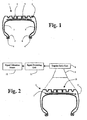
- Figure 1 displays a cross sectional view of an exemplary pneumatic tire and illustrates a possible tread separation zone
- Figure 2 displays a similar cross sectional view of a pneumatic tire illustrating a belt separation zone together with detection apparatus in accordance with the present technology
- Figure 3 displays a graph representing exemplary output voltage da:a of a Doppler Micro-Power Impulse Radar device
- Figure 4 displays an exemplary harmonics analysis graph based on the data from the graph of Figure 3;
- Figure 5 displays an exemplary graph representing the output voltage data of a Doppler Micro-Power Impulse Radar device averaged over 15 tire revolutions;
- Figure 6 displays an exemplary harmonics analysis graph based on the data from the graph of Figure 5;
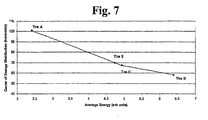
- Figure 7 represents the results of an exemplary analysis useful in explaining the effectiveness of the present methodology.
- the present subject matter is directed towards an improved apparatus and corresponding methodology for the detection of tire related anomalies in a pneumatic tire using a Doppler radar system together with appropriate signal processing systems and methodologies.
- Fig. 1 illustrates an exemplary cross sectional view of a pneumatic tire 1.
- Pneumatic tire 1 consists of a tread block section 2, sidewall sections 5, bead sections 6, beads 4, and a belt section 7. Also illustrated in Fig. 1 is a general area 3 in which tread separation may occur, as will be more thoroughly discussed later.
- Fig. 2 illustrates another exemplary cross sectional view of a pneumatic tire 1.
- the tire 1 illustrated in Fig. 2 includes all of the components of the tire 1 illustrated in Fig.1 but emphasis is made on the illustration of a slightly different section 3' of the tire where belt separation may occur.
- Also illustrated in Fig. 2 is an exemplary representation of apparatus in accordance with the present technology for detecting anomalies within the tire 1.
- a Doppler Radar Unit consisting of a Micro-Power Impulse Radar (MIR) transceiver unit 8 and a directional antenna 9. Electrical signals from the MIR 8 are coupled to a signal processing unit 11 and from the signal processing unit 11 to a signal utilization means 12, both of which will be subsequently explained in further detail.
- MIR Micro-Power Impulse Radar
- the antenna 9 of the Doppler radar unit 8 is directed toward and, in operation, illuminates an exterior tread block area 10 of the tire 1.
- the Doppler radar unit 8 and the signal processing unit 11 function together to detect the rapid change in speed of the tire surface or the subsurface tread belt, as they approach the Doppler radar unit 8.
- the electrical signals produced by the Doppler radar unit 8 are proportional to the radial velocity of the tire surface and of the tread belts below the tire surface.
- Tread belt separation as a phenomenon has to do with the separation of the steel belts from the tread package of a pneumatic tire. Tread belt separation begins at initiation points were the rubber to metal bonds are weak and then tear. These initiation points grow as the tire rubber ages and as flexing causes localized heating. The growth of the initiation points is associated with the formation of pockets. As tread belt separation progresses these pockets grow and coalesce. Tread belt separation can be measured using a technique known as shearography. One exemplary shearographic technique used to measure tread belt separation in pneumatic tires involves placing tires to be tested in a pressure chamber.
- the tire being tested is imaged at normal pressure using, e.g., a CCD-video camera and the image is stored in a memory. Afterwards air is removed from the chamber and the tire being tested is re-imaged. Air pockets within the tire, i.e., sites exhibiting tread belt separation, will expand due to the reduction of air pressure on the outside surfaces of the tire and will cause the tire to deform. Images taken in the deformed state of the tire are electronically subtracted from the stored images and the resulting difference images are displayed. These displayed images are displayed as interference fringes on a monitor and, thereby, reveal instances of tread belt separation in the tire. As is apparent, such a test method, while effective, would be totally unsuitable for use on a moving vehicle, but it does offer a useful, non-destructive technique for comparison/confirmation of tread belt separation detection as disclosed by the present technology.
- the present technology incorporates the use of a Doppler Micro-Power Impulse Radar (MIR) transceiver unit 8 to detect the onset of tread belt separation.
- MIR Micro-Power Impulse Radar
- Particular examples of Doppler MIR for use in accordance with the presently disclosed technology includes Doppler radar transceiver units as described in the aforementioned McEwan Patent Application Publication or any other commercially available products.
- the present technology makes use of a signal processor to process or analyze signals generated by an MIR device to detect the onset of tread belt separation and other tire related anomalies. To illustrate this concept, attention is directed to Fig. 3 that shows an exemplary graph of the output voltage data from a MIR over one revolution, of a test tire.
- Fig. 4 represents a comparison of "energy” (in arbitrary units) vs. harmonics based on the rotational speed of the tire under test.
- Figs. 5 and 6 represent a similar analysis wherein the data shown in Fig. 5 is a representation of the average of 15 revolutions of the tire under test and the graph of Fig. 6 represents the results of an analysis like that represented in Fig. 4 but using the data from Fig. 5.
- the following technique may be employed.
- the average energy of the harmonic energy spectra E av may be computed using the following: and the center of mass, CM, of the harmonic distribution may be calculated as: where E i is the i th energy component of the harmonic spectra and N is the number of samples.
- CM and E av are concerned with the general behavior of all tires experiencing tread belt separation rather than values that might change substantially with tire type, dimension, or even test conditions.
- Go is the initial gauge reading.
- the first gauge reading would be that which represents the tire in its ideal state and to which all subsequent states are referenced.
- MIR Doppler Micro-Power Impulse Radar
- Another modification that may be made to the basic measurement relates to stabilization of the time base and improved averaging.
- noise generated by motion of a vehicle over a less than perfectly smooth road. This noise may arise from multiple sources including the on-vehicle mounting location for the MIR and the relatively independent motion of the vehicle's tires. This relative motion thus creates a certain amount of movement over time which would produce voltage noise in any Doppler based system.
- the presence of large amplitude noise requires that filtering of the sampled signal be undertaken.
- simple time based averaging of the signal may be applied as, e.g., was performed in collecting the data illustrated in Figs. 5 and 6, however, to do averaging over a large number of samples requires a stable time base.
- tread belt separation evolution During the course of evaluating various indications of tread belt separation, at number of tests were performed. One of these tests involved a study of tread belt separation evolution where it was attempted to identify tread belt separation as it formed in tires that were initially new. During the course of the tread belt separation evolution test, it was determined that there were several other effects that could confound the tread belt separation measurement. The first of these was uneven wear. During tread belt separation evolution testing, one of the tires under test began to develop substantial amounts of uneven wear, but no tread belt separation. It was noted that using the same gauge technique developed for tread belt separation that the evolution of uneven wear had substantial similarities to tread belt separation. On the other hand, it was noted that as uneven wear became more developed, the center of mass (CM) of the harmonic distribution did not change as rapidly as the average energy.
- CM center of mass
- windowing means performing analysis for the varied phenomena of interest by selecting ranges of harmonics to study.
- tread belt separation and uneven wear could be measured by studying harmonics ranging from the 3 rd harmonic to the n th harmonic, where n is the fundamental harmonic related to the tread pattern, using methods described above.
- Tread wear could be studied in the tires under study by choosing the harmonics from the n th harmonic to the m th harnonic, where m is the upper overtone of the tread pattern energy, and measuring the average energy.
- Balance and alignment could be studied by observing harmonics 1 and 2.
- n may be the 60 th harmonic while m may be the 120 th harmonic.
- f ( CM j ) , g ( E avi ) , l (CM j ), and m ( E avi ) are empirically determined functions which provide an adequate gauge and can be empirically determined weighting functions to provide adequate sensitivity to the phenomena under study.
- a is a real value constant chosen appropriately to correctly partition the behavior, since it is observed that for different values of the center of mass one can expect differences in the evolution of various phenomena.
- the piecewise function defined in Equation 6 provides a template for a large number of functions that can be used to measure tread belt separation, tread wear, and uneven wear and do so with adequate discrimination.
Applications Claiming Priority (2)
| Application Number | Priority Date | Filing Date | Title |
|---|---|---|---|
| US731198 | 2003-12-09 | ||
| US10/731,198 US7082819B2 (en) | 2003-12-09 | 2003-12-09 | Doppler radar for detecting tire abnormalities |
Publications (2)
| Publication Number | Publication Date |
|---|---|
| EP1542035A1 true EP1542035A1 (de) | 2005-06-15 |
| EP1542035B1 EP1542035B1 (de) | 2008-10-01 |
Family
ID=34523031
Family Applications (1)
| Application Number | Title | Priority Date | Filing Date |
|---|---|---|---|
| EP04105904A Expired - Fee Related EP1542035B1 (de) | 2003-12-09 | 2004-11-18 | Doppler Radar zum Erkennen von Reifen-Anomalien |
Country Status (5)
| Country | Link |
|---|---|
| US (1) | US7082819B2 (de) |
| EP (1) | EP1542035B1 (de) |
| JP (1) | JP5004417B2 (de) |
| CN (1) | CN100523864C (de) |
| DE (1) | DE602004016810D1 (de) |
Cited By (5)
| Publication number | Priority date | Publication date | Assignee | Title |
|---|---|---|---|---|
| WO2007137647A1 (de) * | 2006-05-31 | 2007-12-06 | Contitech Luftfedersysteme Gmbh | Bestimmung der federhöhe einer luftfeder nach einem impuls-laufzeitmessverfahren |
| NL1033445C2 (nl) * | 2007-02-23 | 2008-08-26 | Stms Duiven B V | Inrichting voor het controleren van een band van een voertuig. |
| FR2940190A1 (fr) * | 2008-12-23 | 2010-06-25 | Michelin Soc Tech | Procede d'alerte concernant l'usure d'un pneumatique muni d'un sillon |
| CN104709011A (zh) * | 2013-12-16 | 2015-06-17 | 通用汽车环球科技运作有限责任公司 | 使用rssi和多普勒签名的tpms |
| EP3240704A4 (de) * | 2014-12-31 | 2018-08-15 | Bridgestone Americas Tire Operations, LLC | Radarverschleissmessung für reifenanwendungen |
Families Citing this family (25)
| Publication number | Priority date | Publication date | Assignee | Title |
|---|---|---|---|---|
| WO2010117363A1 (en) * | 2009-04-09 | 2010-10-14 | Michelin Recherche Et Technique, S.A. | Tire metallic cable anomaly detection method and apparatus |
| EP2588299B1 (de) * | 2010-06-30 | 2015-01-28 | Pirelli Tyre S.p.A. | Verfahren und vorrichtung zur kontrolle der ablage halbfertiger elemente für die reifenproduktion |
| RU2443991C1 (ru) * | 2010-07-07 | 2012-02-27 | Сергей Михайлович Мужичек | Способ контроля состояния конструкции летательного аппарата и устройство для его осуществления |
| US9182319B2 (en) * | 2012-06-08 | 2015-11-10 | Xsensor Technology Corporation | Automatic detection and analysis of tire treads |
| RU2502058C1 (ru) * | 2012-08-23 | 2013-12-20 | Сергей Михайлович Мужичек | Способ контроля состояния конструкции летательного аппарата и устройство для его осуществления |
| CN104981685B (zh) * | 2012-11-15 | 2018-05-18 | 安德罗伊德工业有限公司 | 用于确定轮胎均匀性的系统和方法 |
| DE102013016115B4 (de) * | 2013-09-26 | 2022-08-25 | Fraunhofer-Gesellschaft zur Förderung der angewandten Forschung e.V. | Verfahren und Anordnung zur Überwachung des Reifenzustandes eines Fahrzeugreifens mittels Radar |
| RU2545150C1 (ru) * | 2014-03-03 | 2015-03-27 | Владимир Иванович Винокуров | Способ контроля состояния конструкции летательного аппарата |
| CN105784338B (zh) * | 2014-12-19 | 2018-06-29 | 安徽容知日新科技股份有限公司 | 旋转设备基础频率的高次谐波定位方法 |
| CN106864178B (zh) * | 2016-01-07 | 2018-07-31 | 西华大学 | 一种新型轮胎安全监测装置 |
| CN105760679B (zh) * | 2016-02-25 | 2018-01-26 | 安徽佳通乘用子午线轮胎有限公司 | 基于路试数据的轮胎异常磨损程度判断方法 |
| US20170254897A1 (en) * | 2016-03-02 | 2017-09-07 | GM Global Technology Operations LLC | Systems and methods for remote monitoring with radar |
| WO2017156216A1 (en) * | 2016-03-09 | 2017-09-14 | Compagnie Generale Des Etablissements Michelin | Driving companion tread-life indicator system |
| CN106183662B (zh) * | 2016-07-08 | 2018-10-30 | 深圳市元征科技股份有限公司 | 轮胎状态检测方法及装置 |
| FR3066721B1 (fr) * | 2017-05-23 | 2019-06-07 | Continental Automotive France | Procede d'identification d'au moins un emetteur de surveillance de la pression d'un pneumatique d'un vehicule automobile par association avec une des roues dudit vehicule automobile |
| CN107499069A (zh) * | 2017-09-08 | 2017-12-22 | 江苏金坛绿能新能源科技有限公司 | 车辆轮胎爆胎预警装置 |
| EP3483568A1 (de) * | 2017-11-13 | 2019-05-15 | Siemens Aktiengesellschaft | Winkelsensor mit erfassung der drehstellung mit radartechnik |
| BR112020013129A2 (pt) | 2017-12-29 | 2020-12-01 | Bridgestone Bandag, Llc | máquina de raspagem de pneu, e, método para fabricação de carcaça de pneu recauchutado. |
| US10852423B2 (en) * | 2018-03-07 | 2020-12-01 | The Government Of The United States, As Represented By The Secretary Of The Army | Vehicle-mounted wave transmission and wave response reception |
| JP2019203831A (ja) * | 2018-05-25 | 2019-11-28 | 住友ゴム工業株式会社 | 空気入りタイヤ、タイヤ摩耗測定方法およびタイヤ摩耗測定システムならびにセンサモジュール |
| US10820474B2 (en) | 2018-10-11 | 2020-11-03 | Cnh Industrial Canada, Ltd. | System for estimating field conditions and associated methods for adjusting operating parameters of an agricultural machine based on estimated field conditions |
| US11014570B2 (en) | 2018-12-10 | 2021-05-25 | Continental Automotive Systems, Inc. | Front car rear tire anomalies detection system and related methods |
| DE102019202062A1 (de) * | 2019-02-15 | 2020-08-20 | Zf Friedrichshafen Ag | Zustandserfassungsvorrichtung, Verfahren zum Erfassen eines Zustands sowie Fahrzeug |
| DE102019208251A1 (de) | 2019-06-06 | 2020-12-10 | Continental Reifen Deutschland Gmbh | Verfahren zur Inspektion von technischen Gummiartikeln mit einer Festigkeitsträgerlage und Vorrichtung zur Durchführung des Verfahrens sowie die Verwendungen der Vorrichtung |
| CN115798081A (zh) * | 2023-02-07 | 2023-03-14 | 中国第一汽车股份有限公司 | 车辆的信息处理方法、装置、存储介质、处理器和车辆 |
Citations (4)
| Publication number | Priority date | Publication date | Assignee | Title |
|---|---|---|---|---|
| US3919882A (en) * | 1974-02-11 | 1975-11-18 | Donald R Wells | Tire inspection apparatus and method |
| US6028508A (en) * | 1999-02-25 | 2000-02-22 | Mason; Daniel B. | System for the detection of tire tread separation |
| DE10119352C1 (de) * | 2001-04-20 | 2002-11-28 | Autoliv Dev | Verfahren zur Bestimmung der Profileigenschaften eines Fahrzeugreifens während der Fahrt |
| US20020189336A1 (en) * | 2001-06-15 | 2002-12-19 | Mcewan Technologies, Llc | Radar monitoring system for tires and wheels |
Family Cites Families (23)
| Publication number | Priority date | Publication date | Assignee | Title |
|---|---|---|---|---|
| US1592937A (en) * | 1921-12-27 | 1926-07-20 | Western Electric Co | Method of and means for producing harmonics |
| US4450431A (en) * | 1981-05-26 | 1984-05-22 | Hochstein Peter A | Condition monitoring system (tire pressure) |
| US4570152A (en) | 1984-04-23 | 1986-02-11 | Hyperion Corporation | Magnetic tire monitor system |
| US4609905A (en) * | 1984-05-11 | 1986-09-02 | Eaton Corporation | Tire condition monitoring system |
| JPS62295709A (ja) * | 1986-06-16 | 1987-12-23 | Hitachi Ltd | タイヤ異常検出装置 |
| CN2077810U (zh) * | 1990-08-18 | 1991-05-29 | 苏克敏 | 拖车轮胎气压监视报警器 |
| JP3182836B2 (ja) * | 1992-02-21 | 2001-07-03 | 株式会社デンソー | タイヤバランス検知装置 |
| US5436612A (en) | 1994-03-30 | 1995-07-25 | Aduddell; Richard N. | Audible vehicle monitoring apparatus |
| US5569848A (en) * | 1995-01-06 | 1996-10-29 | Sharp; Everett H. | System, method and apparatus for monitoring tire inflation pressure in a vehicle tire and wheel assembly |
| GB9515454D0 (en) * | 1995-07-27 | 1995-09-27 | Sun Electric Uk Ltd | Testing vehicle tyres |
| CN2338193Y (zh) * | 1998-05-05 | 1999-09-15 | 王传轩 | 轮胎过压、漏气预警监视仪 |
| FR2780682A1 (fr) * | 1998-07-06 | 2000-01-07 | Michelin Rech Tech | Procede et dispositif de detection d'une condition de roulage a plat d'un pneumatique - inserts, roues et pneumatiques concus pour ce procede |
| US6255940B1 (en) | 1999-10-01 | 2001-07-03 | The Goodyear Tire & Rubber Company | Apparatus for monitoring a condition of a tire |
| JP4868689B2 (ja) * | 2000-06-23 | 2012-02-01 | 株式会社ブリヂストン | 路面状態推定方法、及び、路面状態推定装置 |
| DE10057059C2 (de) * | 2000-11-17 | 2003-12-24 | Transense Technologies Plc | Verfahren und Vorrichtung zur Meßwertüberwachung durch Frequenzanalyse von modulierter Rückstreuung |
| FR2816887B1 (fr) * | 2000-11-20 | 2003-03-14 | Dufournier Technologies | Procede et dispositif detecteur d'usure des pneumatiques ou bandes de roulement et surfaces ou zones d'usure analogues |
| US6759952B2 (en) * | 2001-07-06 | 2004-07-06 | Trw Inc. | Tire and suspension warning and monitoring system |
| EP1279526B1 (de) * | 2001-07-24 | 2008-10-08 | TÜV Automotive GmbH Unternehmensgruppe TÜV Süddeutschland | Verfahren und System zum Überwachen des Betriebs eines Fahrzeugreifens sowie Fahrzeugreifen |
| JP2003080912A (ja) * | 2001-09-11 | 2003-03-19 | Bridgestone Corp | 回転体の異常検知システム及びこれを用いたサービス提供方法 |
| DE10153072B4 (de) * | 2001-10-30 | 2004-11-04 | Continental Aktiengesellschaft | Verfahren zur Ermittlung sich anbahnender Laufstreifenablösungen eines Luftreifens an einem Fahrzeug |
| US20030080852A1 (en) * | 2001-10-31 | 2003-05-01 | International Business Machines Corporation | Secure smart card |
| JP4231254B2 (ja) * | 2002-08-02 | 2009-02-25 | 横浜ゴム株式会社 | タイヤの歪み状態検出方法、歪み状態検出装置及びそのタイヤ |
| JP2004205437A (ja) * | 2002-12-26 | 2004-07-22 | Central Japan Railway Co | 摩耗判定システム、摩耗判定装置および摩耗判定プログラム |
-
2003
- 2003-12-09 US US10/731,198 patent/US7082819B2/en not_active Expired - Lifetime
-
2004
- 2004-11-18 EP EP04105904A patent/EP1542035B1/de not_active Expired - Fee Related
- 2004-11-18 DE DE602004016810T patent/DE602004016810D1/de active Active
- 2004-12-09 JP JP2004357298A patent/JP5004417B2/ja not_active Expired - Fee Related
- 2004-12-09 CN CNB2004100985387A patent/CN100523864C/zh not_active Expired - Fee Related
Patent Citations (4)
| Publication number | Priority date | Publication date | Assignee | Title |
|---|---|---|---|---|
| US3919882A (en) * | 1974-02-11 | 1975-11-18 | Donald R Wells | Tire inspection apparatus and method |
| US6028508A (en) * | 1999-02-25 | 2000-02-22 | Mason; Daniel B. | System for the detection of tire tread separation |
| DE10119352C1 (de) * | 2001-04-20 | 2002-11-28 | Autoliv Dev | Verfahren zur Bestimmung der Profileigenschaften eines Fahrzeugreifens während der Fahrt |
| US20020189336A1 (en) * | 2001-06-15 | 2002-12-19 | Mcewan Technologies, Llc | Radar monitoring system for tires and wheels |
Non-Patent Citations (1)
| Title |
|---|
| AZEVEDO S ET AL: "Micropower impulse radar", IEEE POTENTIALS IEEE USA, vol. 16, no. 2, May 1997 (1997-05-01), pages 15 - 20, XP002321494, ISSN: 0278-6648 * |
Cited By (10)
| Publication number | Priority date | Publication date | Assignee | Title |
|---|---|---|---|---|
| WO2007137647A1 (de) * | 2006-05-31 | 2007-12-06 | Contitech Luftfedersysteme Gmbh | Bestimmung der federhöhe einer luftfeder nach einem impuls-laufzeitmessverfahren |
| NL1033445C2 (nl) * | 2007-02-23 | 2008-08-26 | Stms Duiven B V | Inrichting voor het controleren van een band van een voertuig. |
| WO2008103026A1 (en) * | 2007-02-23 | 2008-08-28 | Stms Duiven B.V. | Device for inspecting a vehicle tyre |
| FR2940190A1 (fr) * | 2008-12-23 | 2010-06-25 | Michelin Soc Tech | Procede d'alerte concernant l'usure d'un pneumatique muni d'un sillon |
| WO2010072962A1 (fr) * | 2008-12-23 | 2010-07-01 | Societe De Technologie Michelin | Procede d'alerte concernant l'usure d'un pneumatique muni d'un sillon |
| US8904869B2 (en) | 2008-12-23 | 2014-12-09 | Compagnie Generale Des Establissements Michelin | Alarm method for indicating the wear of a tyre with a groove |
| CN104709011A (zh) * | 2013-12-16 | 2015-06-17 | 通用汽车环球科技运作有限责任公司 | 使用rssi和多普勒签名的tpms |
| EP3240704A4 (de) * | 2014-12-31 | 2018-08-15 | Bridgestone Americas Tire Operations, LLC | Radarverschleissmessung für reifenanwendungen |
| US10647164B2 (en) | 2014-12-31 | 2020-05-12 | Bridgestone Americas Tire Operations, Llc | Radar wear sensing for tire applications |
| US11084332B2 (en) | 2014-12-31 | 2021-08-10 | Bridgestone Americas Tire Operations, Llc | Radar wear sensing for tire applications |
Also Published As
| Publication number | Publication date |
|---|---|
| DE602004016810D1 (de) | 2008-11-13 |
| US7082819B2 (en) | 2006-08-01 |
| CN100523864C (zh) | 2009-08-05 |
| US20050120787A1 (en) | 2005-06-09 |
| CN1627098A (zh) | 2005-06-15 |
| EP1542035B1 (de) | 2008-10-01 |
| JP5004417B2 (ja) | 2012-08-22 |
| JP2005186929A (ja) | 2005-07-14 |
Similar Documents
| Publication | Publication Date | Title |
|---|---|---|
| EP1542035B1 (de) | Doppler Radar zum Erkennen von Reifen-Anomalien | |
| JP4091083B2 (ja) | タイヤ内部故障検知装置およびタイヤ内部故障検知方法 | |
| US10399396B2 (en) | System and method for determining at least one tire contact area parameter characterizing a dimension of a tire contact area on a tire of a wheel of a vehicle | |
| US20090139327A1 (en) | Method and a system for determining wheel imbalances of at least one wheel on a vehicle | |
| EP1678019B1 (de) | Verfahren und vorrichtung zur ermittlung der fahrflächenrauhigkeit eines reifens | |
| EP2039540A2 (de) | System, Reifen und Verfahren zum Bestimmen des Verhaltens eines Reifens in Bewegung | |
| EP1767422A1 (de) | Verfahren und Vorrichtung zur Schätzung des Radverhaltens bei Kurvenfahrt | |
| EP2137013B1 (de) | System, verfahren und rechnerprogramm zum schätzen des drucks | |
| EP1906165A1 (de) | Verfahren und einrichtung zum berechnen des betrags einer in einem rad erzeugten kurvenkraft | |
| JP2014530347A (ja) | 自動車用シャシシステムにおける構成部品の欠陥診断方法及び装置 | |
| JP2010521364A (ja) | タイヤ空気圧分類ベースのタイヤ空気圧監視 | |
| CN112428753B (zh) | 一种车辆轮胎异常识别方法、装置、电子设备及存储介质 | |
| US20110257902A1 (en) | Method and system for determining the potential friction between a vehicle tyre and a rolling surface | |
| Yang et al. | Experimental investigation of tire dynamic strain characteristics for developing strain-based intelligent tire system | |
| US7941255B2 (en) | Process and apparatus for detecting damper damage | |
| US6594558B1 (en) | Method for verifying tires of vehicles in the driving state | |
| JP2007064877A (ja) | タイヤの故障発生検知方法およびタイヤの故障発生検知装置 | |
| US20040148074A1 (en) | System and method for monitoring the vehicle dynamics of a vehicle | |
| CN113858893A (zh) | 一种极超前预警轮胎爆胎危险的监测装置及方法 | |
| KR101891889B1 (ko) | 휴대용 타이어 비드 슬립 측정장치 | |
| EP4357168A1 (de) | Reifenlastüberwachung | |
| CN114728557B (zh) | 用于评估车辆沿着路段行驶期间的车身运动的方法和系统 | |
| JP7100544B2 (ja) | タイヤ振動特性評価方法 | |
| RU2350918C1 (ru) | Способ оценки состояния дорожных конструкций | |
| US20210183176A1 (en) | System and method for inspecting vehicle pull |
Legal Events
| Date | Code | Title | Description |
|---|---|---|---|
| PUAI | Public reference made under article 153(3) epc to a published international application that has entered the european phase |
Free format text: ORIGINAL CODE: 0009012 |
|
| AK | Designated contracting states |
Kind code of ref document: A1 Designated state(s): AT BE BG CH CY CZ DE DK EE ES FI FR GB GR HU IE IS IT LI LU MC NL PL PT RO SE SI SK TR |
|
| AX | Request for extension of the european patent |
Extension state: AL HR LT LV MK YU |
|
| 17P | Request for examination filed |
Effective date: 20050722 |
|
| AKX | Designation fees paid |
Designated state(s): DE FR GB IT |
|
| GRAP | Despatch of communication of intention to grant a patent |
Free format text: ORIGINAL CODE: EPIDOSNIGR1 |
|
| RIC1 | Information provided on ipc code assigned before grant |
Ipc: G01S 13/88 20060101AFI20080310BHEP Ipc: B60C 11/24 20060101ALI20080310BHEP Ipc: G01M 17/02 20060101ALI20080310BHEP Ipc: B60C 19/00 20060101ALI20080310BHEP Ipc: B60C 23/06 20060101ALI20080310BHEP |
|
| GRAS | Grant fee paid |
Free format text: ORIGINAL CODE: EPIDOSNIGR3 |
|
| GRAA | (expected) grant |
Free format text: ORIGINAL CODE: 0009210 |
|
| RIN1 | Information on inventor provided before grant (corrected) |
Inventor name: THIESEN, JACK Inventor name: O'BRIEN, GEORGE PHILLIPS |
|
| RAP1 | Party data changed (applicant data changed or rights of an application transferred) |
Owner name: MICHELIN RECHERCHE ET TECHNIQUE S.A. Owner name: SOCIETE DE TECHNOLOGIE MICHELIN |
|
| AK | Designated contracting states |
Kind code of ref document: B1 Designated state(s): DE FR GB IT |
|
| REG | Reference to a national code |
Ref country code: GB Ref legal event code: FG4D |
|
| REF | Corresponds to: |
Ref document number: 602004016810 Country of ref document: DE Date of ref document: 20081113 Kind code of ref document: P |
|
| PLBE | No opposition filed within time limit |
Free format text: ORIGINAL CODE: 0009261 |
|
| STAA | Information on the status of an ep patent application or granted ep patent |
Free format text: STATUS: NO OPPOSITION FILED WITHIN TIME LIMIT |
|
| 26N | No opposition filed |
Effective date: 20090702 |
|
| REG | Reference to a national code |
Ref country code: FR Ref legal event code: PLFP Year of fee payment: 12 |
|
| PGFP | Annual fee paid to national office [announced via postgrant information from national office to epo] |
Ref country code: GB Payment date: 20151118 Year of fee payment: 12 |
|
| REG | Reference to a national code |
Ref country code: FR Ref legal event code: PLFP Year of fee payment: 13 |
|
| GBPC | Gb: european patent ceased through non-payment of renewal fee |
Effective date: 20161118 |
|
| REG | Reference to a national code |
Ref country code: FR Ref legal event code: PLFP Year of fee payment: 14 |
|
| PG25 | Lapsed in a contracting state [announced via postgrant information from national office to epo] |
Ref country code: GB Free format text: LAPSE BECAUSE OF NON-PAYMENT OF DUE FEES Effective date: 20161118 |
|
| PGFP | Annual fee paid to national office [announced via postgrant information from national office to epo] |
Ref country code: IT Payment date: 20201124 Year of fee payment: 17 Ref country code: FR Payment date: 20201120 Year of fee payment: 17 Ref country code: DE Payment date: 20201119 Year of fee payment: 17 |
|
| REG | Reference to a national code |
Ref country code: DE Ref legal event code: R119 Ref document number: 602004016810 Country of ref document: DE |
|
| PG25 | Lapsed in a contracting state [announced via postgrant information from national office to epo] |
Ref country code: DE Free format text: LAPSE BECAUSE OF NON-PAYMENT OF DUE FEES Effective date: 20220601 |
|
| PG25 | Lapsed in a contracting state [announced via postgrant information from national office to epo] |
Ref country code: FR Free format text: LAPSE BECAUSE OF NON-PAYMENT OF DUE FEES Effective date: 20211130 |
|
| PG25 | Lapsed in a contracting state [announced via postgrant information from national office to epo] |
Ref country code: IT Free format text: LAPSE BECAUSE OF NON-PAYMENT OF DUE FEES Effective date: 20211118 |