EP1541761A1 - Rakelvorrichtung - Google Patents
Rakelvorrichtung Download PDFInfo
- Publication number
- EP1541761A1 EP1541761A1 EP04106457A EP04106457A EP1541761A1 EP 1541761 A1 EP1541761 A1 EP 1541761A1 EP 04106457 A EP04106457 A EP 04106457A EP 04106457 A EP04106457 A EP 04106457A EP 1541761 A1 EP1541761 A1 EP 1541761A1
- Authority
- EP
- European Patent Office
- Prior art keywords
- doctor
- squeegee
- material web
- pressing
- magnet
- Prior art date
- Legal status (The legal status is an assumption and is not a legal conclusion. Google has not performed a legal analysis and makes no representation as to the accuracy of the status listed.)
- Withdrawn
Links
Images
Classifications
-
- D—TEXTILES; PAPER
- D21—PAPER-MAKING; PRODUCTION OF CELLULOSE
- D21G—CALENDERS; ACCESSORIES FOR PAPER-MAKING MACHINES
- D21G3/00—Doctors
-
- B—PERFORMING OPERATIONS; TRANSPORTING
- B05—SPRAYING OR ATOMISING IN GENERAL; APPLYING FLUENT MATERIALS TO SURFACES, IN GENERAL
- B05C—APPARATUS FOR APPLYING FLUENT MATERIALS TO SURFACES, IN GENERAL
- B05C11/00—Component parts, details or accessories not specifically provided for in groups B05C1/00 - B05C9/00
- B05C11/02—Apparatus for spreading or distributing liquids or other fluent materials already applied to a surface ; Controlling means therefor; Control of the thickness of a coating by spreading or distributing liquids or other fluent materials already applied to the coated surface
- B05C11/023—Apparatus for spreading or distributing liquids or other fluent materials already applied to a surface
- B05C11/025—Apparatus for spreading or distributing liquids or other fluent materials already applied to a surface with an essentially cylindrical body, e.g. roll or rod
-
- B—PERFORMING OPERATIONS; TRANSPORTING
- B05—SPRAYING OR ATOMISING IN GENERAL; APPLYING FLUENT MATERIALS TO SURFACES, IN GENERAL
- B05C—APPARATUS FOR APPLYING FLUENT MATERIALS TO SURFACES, IN GENERAL
- B05C11/00—Component parts, details or accessories not specifically provided for in groups B05C1/00 - B05C9/00
- B05C11/02—Apparatus for spreading or distributing liquids or other fluent materials already applied to a surface ; Controlling means therefor; Control of the thickness of a coating by spreading or distributing liquids or other fluent materials already applied to the coated surface
- B05C11/04—Apparatus for spreading or distributing liquids or other fluent materials already applied to a surface ; Controlling means therefor; Control of the thickness of a coating by spreading or distributing liquids or other fluent materials already applied to the coated surface with blades
- B05C11/041—Apparatus for spreading or distributing liquids or other fluent materials already applied to a surface ; Controlling means therefor; Control of the thickness of a coating by spreading or distributing liquids or other fluent materials already applied to the coated surface with blades characterised by means for positioning, loading, or deforming the blades
-
- B—PERFORMING OPERATIONS; TRANSPORTING
- B05—SPRAYING OR ATOMISING IN GENERAL; APPLYING FLUENT MATERIALS TO SURFACES, IN GENERAL
- B05C—APPARATUS FOR APPLYING FLUENT MATERIALS TO SURFACES, IN GENERAL
- B05C11/00—Component parts, details or accessories not specifically provided for in groups B05C1/00 - B05C9/00
- B05C11/02—Apparatus for spreading or distributing liquids or other fluent materials already applied to a surface ; Controlling means therefor; Control of the thickness of a coating by spreading or distributing liquids or other fluent materials already applied to the coated surface
- B05C11/04—Apparatus for spreading or distributing liquids or other fluent materials already applied to a surface ; Controlling means therefor; Control of the thickness of a coating by spreading or distributing liquids or other fluent materials already applied to the coated surface with blades
- B05C11/044—Apparatus for spreading or distributing liquids or other fluent materials already applied to a surface ; Controlling means therefor; Control of the thickness of a coating by spreading or distributing liquids or other fluent materials already applied to the coated surface with blades characterised by means for holding the blades
-
- D—TEXTILES; PAPER
- D21—PAPER-MAKING; PRODUCTION OF CELLULOSE
- D21H—PULP COMPOSITIONS; PREPARATION THEREOF NOT COVERED BY SUBCLASSES D21C OR D21D; IMPREGNATING OR COATING OF PAPER; TREATMENT OF FINISHED PAPER NOT COVERED BY CLASS B31 OR SUBCLASS D21G; PAPER NOT OTHERWISE PROVIDED FOR
- D21H25/00—After-treatment of paper not provided for in groups D21H17/00 - D21H23/00
- D21H25/08—Rearranging applied substances, e.g. metering, smoothing; Removing excess material
- D21H25/10—Rearranging applied substances, e.g. metering, smoothing; Removing excess material with blades
-
- D—TEXTILES; PAPER
- D21—PAPER-MAKING; PRODUCTION OF CELLULOSE
- D21H—PULP COMPOSITIONS; PREPARATION THEREOF NOT COVERED BY SUBCLASSES D21C OR D21D; IMPREGNATING OR COATING OF PAPER; TREATMENT OF FINISHED PAPER NOT COVERED BY CLASS B31 OR SUBCLASS D21G; PAPER NOT OTHERWISE PROVIDED FOR
- D21H25/00—After-treatment of paper not provided for in groups D21H17/00 - D21H23/00
- D21H25/08—Rearranging applied substances, e.g. metering, smoothing; Removing excess material
- D21H25/12—Rearranging applied substances, e.g. metering, smoothing; Removing excess material with an essentially cylindrical body, e.g. roll or rod
Definitions
- the invention relates to a squeegee device for comparison or dosing a liquid or pasty applied to a running surface Application medium, wherein the running surface of the direct order the surface a web, in particular a paper or board web and indirect Order is an application element, such as an applicator roll, which the Application medium to the web dispenses, with a against the current Surface pressing squeegee element, which at its foot part in a Holding device is releasably fixed.
- an application element such as an applicator roll
- a Application medium such as coating color
- facilities Applicators within a coating machine in the manufacture and / or Finishing the material web
- This running surface is at direct Order the material web itself or, in case of indirect order, an application element, which dispenses the application medium to the material web.
- the application is often carried out in excess, which is why the applied layer scraped to the desired coating weight in g / m 2 with a so-called doctor element - that is metered - must be.
- doctor elements are elastic doctor blades or rotatable, in one Doctor bed recorded and by an elastic blade-like retaining strip worn Rollrakelstäbe in question.
- a squeegee device as a holding device for the respective Doctor blade a support bar, a terminal block and at least one Clamping hose on.
- the squeegee element i. the foot part of the elastic Squeegee blade or the elastic retaining strip, between the support strip and terminal strip clamped.
- An inflatable clamp or pressure hose ensures that Clamping and releasing the squeegee element.
- a doctor blade holder is described with a retaining strip for receiving a doctor element.
- the retaining strip is fixed in a support beam by means of a magnet or by a negative pressure.
- the squeegee element is clamped with pressure hoses in the retaining strip.
- this arrangement can not solve the above problem, since the application medium - as described above - between the squeegee and the Andrückschläuchen and between the doctor element and the clamping point of the retaining strip penetrate and can lead to contamination. Consequently, longer machine downtimes due to increased cleaning effort are to be expected here.
- the invention has the object, a doctor device of the type mentioned be improved so that in the future, the machine downtime, which for the replacement of the squeegee element are required to be significantly reduced can.
- the invention solves this problem by a squeegee device of the type mentioned, in which the holding device according to the invention is one which generates an attractive force for fixing the squeegee element. Due to the attraction for fixing the doctor element eliminates the previously required clamping between two clamping strips, ie between support and terminal block. In addition, clamping or pressure hoses are no longer necessary. This contamination of the clamping point is not possible in the future. Since the squeegee element, ie, its foot part in the fixed state covers the region of the holding device which generates the attractive force, the area of the holding device which generates the force of attraction can not be contaminated by the stripped and running down application medium. Thus, no time-consuming cleaning work is required.
- Another advantage of the invention is that no more movable clamping strips are needed, so that the doctor element, in particular a doctor blade, can no longer be squeezed by the holding device.
- By eliminating the movable clamping strips also installation space is gained.
- the clamping strips previously had to hold the doctor element from two sides. Now it is sufficient for a secure hold of the doctor element, when the attraction of one side acts on the doctor element.
- the holding device with at least one Permanent magnet with electrical shutdown and / or at least one Electromagnet provided.
- the permanent and / or electromagnet is a inexpensive alternative to the attraction for fixing the doctor element to create.
- the permanent magnet and / or the electromagnet can spread over the entire width of the Stretch material web. In this way, a uniform holding force, which is the Squeegee element fixed, guaranteed.
- the doctor element is expediently when using the at least one Permanent and / or electromagnet magnetizable.
- the holding device of a vacuum clamping device consist. This is a cost effective alternative as well to create an attraction for fixing the doctor element, for example, if there are no electrical connection options for an electromagnet Are available.
- the vacuum clamping device may have at least one suction opening. This suction opening can be over the entire width of the web or else extend the machine or doctor device or a slightly smaller width than have the material web. In this way, a uniform holding force for Secured fixation of the squeegee element.
- multiple intake ports in one be arranged certain distance next to each other in the support element. Then that is To choose the distance between the individual intake openings so that the Squeegee element is still held securely.
- the doctor device is also known to have at least one Pressing element for pressing the doctor element against the fibrous web Mistake.
- the pressure element is adjustable.
- a known profile math This is done with a variety and evenly over the web width distributed arranged actuators reached.
- the actuators are single controllable to the function of the doctor element over the working width away guarantee.
- adjusting spindles can be used to adjust the desired contact forces are used. This is also a lot cost-effective solution.
- the invention relates to a coating device according to the invention a Doctor device according to one of claims 1 to 12.
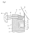
- a squeegee device 10 comprising a squeegee bar B, which carries a holding device 11 for a squeegee element 12.
- the holding device 11 in turn comprises a support strip 13, in which a magnet 14 is arranged.
- the magnet 14 generates an attraction force for fixing the doctor element 12, which is designed here as an elastic coating blade.
- the doctor element 12 has the task of a running surface 15, which is here to be a fibrous web of paper, previouslyletsstreif with an application device, not shown in excess applied application medium M - for example, coating color.
- the remaining on the running surface or fibrous web layer is designated in Figure 1 with S. This achieves the desired coating weight in g / m 2 remaining on the paper web.
- a recess 16 is provided for receiving the magnet 14.
- the Magnet 14 protected against contamination, housed. It also obscures that Doctor blade 12, i. the elastic doctor blade or an elastic retaining strip for a metering rod (as shown in Figure 2) at its foot 12a the magnet 14, whereby the magnet 14 in addition to contamination by the excess the doctor element 12 running down application medium M 'is protected. Consequently are when changing the doctor element 12 no elaborate cleaning perform more, so that the required machine downtime on a Minimum be reduced.
- the magnet 14 may be a permanent and / or a Be electromagnet. The magnet 14 may extend over the entire width of the Fiber web 15 extend.
- doctor element 12 is located over the entire Width of the fibrous web 15 on the magnet 14, whereby the doctor element 12th is optimally held by the magnet 14.
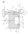
- the figure 2 shows, the squeegee device - here Denoted by 20 - one of an existing as in FIG. 1 recess 16 branching intake passage 25.
- the intake passage 25 is provided with at least one Suction opening 26 is provided, which merges into the recess 16.
- the squeegee element 12 i. in this variant according to FIG. 2, this is the blade-like retaining strip 12 'for a doctor blade 31 running in a doctor bed 30, when stripping the excess coating medium reliably in position held.
- the intake passage 25 also in the recess 16 in front of a Pollution is protected by the running down application medium M 'and through the foot 12a 'the retaining strip 12 is covered, so can the Intake port 26 and the foot part 12a ', in particular in the clamping area - in Area of the recess 16 - do not pollute. Thus omitted in this Variant that extend the machine downtime Cleaning.
- the Intake passage 25 extends over the entire width of the material web 15. It is but also possible, several (not shown) narrower intake ducts to arrange next to each other along the entire width of the web 15.
- both variants of the doctor devices 10 and 20 at least one Pressing element 41, with which the upper portion of the doctor element 12 , .30 / 31 is pressed against the fibrous web 15. Sensitive to the contact pressure to be able to adjust and to be able to keep the set contact pressure, is a Variety of juxtaposed pressing elements 41 with adjusting (Actuators) advantageous. These then act in individual work areas.
- adjusting spindles 42 are provided for this, which are as shown in the example, for. B. can be operated with a handwheel 43.
- the pressure system works in such a way that, due to different settings of the adjusting spindles 42, spatially different pressure forces are transmitted to the blade tip 12b or the doctor blade 31 via the doctor blade bed 30 across the width of the fibrous web 15 or the entire device 10 or 20.
- the adjusting spindles 42 can also be motorized by means of appropriate servomotors control, regulate and adjust.
Landscapes
- Coating Apparatus (AREA)
Abstract
Description
Diese Anordnung kann jedoch keine Lösung zu dem oben genannten Problem geben, da das Auftragsmedium - wie oben beschrieben - zwischen dem Rakelelement und den Andrückschläuchen und zwischen dem Rakelelement und der Einspannstelle der Halteleiste eindringen und zu Verschmutzungen führen kann. Folglich sind auch hier längere Maschinenstillstandszeiten wegen eines erhöhten Reinigungsaufwandes zu erwarten.
Durch den Wegfall der beweglichen Einspannleisten wird außerdem Einbauraum gewonnen. Die Einspannleisten mussten das Rakelelement bisher von zwei Seiten halten. Jetzt genügt es für einen sicheren Halt des Rakelelements, wenn die Anziehungskraft von einer Seite auf das Rakelelement wirkt.
- Fig. 1
- eine Seitenansicht im Schnitt durch eine erste Ausführungsform einer Rakelvorrichtung;
- Fig. 2
- eine zweite Ausführungsform einer Rakelvorrichtung.
Das Rakelelement 12 hat die Aufgabe, von einer laufenden Oberfläche 15, die hier eine Faserstoffbahn aus Papier sein soll, das zuvor mit einer nicht dargestellten Auftragseinrichtung im Überschuss aufgebrachte Auftragsmedium M - beispielsweise Streichfarbe - abzustreif en. Die auf der laufenden Oberfläche bzw. Faserstoffbahn verbliebene Schicht ist in Figur 1 mit S bezeichnet. Dadurch wird das auf der Papierbahn verbleibende, gewünschte Strichgewicht in g/m2 erreicht.
Das Andrucksystem funktioniert derart, dass durch unterschiedliche Einstellungen der Verstellspindeln 42 über die Breite der Faserstoffbahn 15 bzw. der gesamten Vorrichtung 10 bzw. 20 örtlich unterschiedliche Andruckkräfte an die Klingenspitze 12b bzw. den Rakelstab 31 über Rakelbett 30 weitergegeben werden.
- 10, 20
- Rakelvorrichtung
- 11
- Halteeinrichtung
- 12
- Rakelelement
- 12'
- Halteleiste
- 12a
- Fußteil
- 12a'
- Halteleiste
- 13
- Stützleiste
- 13b
- Wandungsteil
- 14
- Magnet
- 15
- laufende Oberfläche, Materialbahn
- 16
- Ausnehmung
- 25
- Ansaugkanal
- 26
- Ansaugöffnung
- 28
- Vakuumpumpe
- 30
- Rakelbett
- 31
- Rakelstab
- 32
- Dichtung
- 41
- Andrückelement
- 42
- Verstellspindeln
- 43
- Handrad
- B
- Rakelbalken
- M
- Auftragsmedium
- M'
- herunterlaufendes Auftragsmedium
- S
- Schicht
Claims (13)
- Rakelvorrichtung zum Vergleichmäßigen oder Dosieren eines auf eine laufende Oberfläche aufgebrachten flüssigen oder pastösen Auftragsmediums, wobei die laufende Oberfläche bei direktem Auftrag die Oberfläche einer Materialbahn, insbesondere eine Papier- oder Kartonbahn und bei indirektem Auftrag ein Auftragselement, beispielsweise eine Auftragswalze ist, welche das Auftragsmedium an die Materialbahn abgibt, mit einem gegen die laufende Oberfläche drückenden Rakelelement, welches an seinem Fußteil in einer Halteeinrichtung lösbar fixiert ist, dadurch gekennzeichnet, dass die Halteeinrichtung (11) derart ausgebildet ist, dass sie eine Anziehungskraft zur Fixierung des Rakelelements (12, 12') erzeugt.
- Rakelvorrichtung (10) nach Anspruch 1, dadurch gekennzeichnet, dass die Halteeinrichtung (11) eine Stützleiste (13) mit einer Ausnehmung (16) aufweist, in der mindestens ein Magnet (14) in Form mindestens eines Permanent- und/oder mindestens eines Elektromagnetes (14) angeordnet ist.
- Rakelvorrichtung (10) nach Anspruch 2, dadurch gekennzeichnet, dass sich der Magnet (14) im Wesentlichen über die ganze Breite der Materialbahn (15) erstreckt.
- Rakelvorrichtung (10) nach Anspruch 2, dadurch gekennzeichnet, dass die mehreren Magnete (14) in einem bestimmten Abstand nebeneinander angeordnet sind.
- Rakelvorrichtung (10) nach einem der Ansprüche 2 bis 4, dadurch gekennzeichnet, dass das Rakelelement (12) magnethaftbar ist.
- Rakelvorrichtung (20) nach Anspruch 1, dadurch gekennzeichnet, dass die Halteeinrichtung (11) als Unterdruck-Einrichtung ausgebildet ist und dafür die Stützleiste (13) mit wenigstens einem von der Ausnehmung (16) abzweigenden Ansaugkanal (25) mit wenigstens einer Ansaugöffnung (26) versehen ist.
- Rakelvorrichtung (20) nach Anspruch 6, dadurch gekennzeichnet, dass sich die Ansaugöffnung (26) zumindest über die ganze Breite der Materialbahn (15) erstreckt.
- Rakelvorrichtung (20) nach Anspruch 6, dadurch gekennzeichnet, dass mehrere Ansaugöffnungen (26) in einem bestimmten Abstand nebeneinander vorgesehen sind.
- Rakelvorrichtung (20) nach einem der Ansprüche 6 bis 8, dadurch gekennzeichnet, dass das Rakelelement (12) als rotierbarer Rakelstab (31) ausgebildet ist, der in einem Rakelbett (30) lagert, welches von einer klingenartigen Halteleiste (12') getragen ist und ein Fußteil (12a') aufweist, wobei zwischen dem Fußteil (12a') des Rakelelementes (12', 30, 31) und dem zugeordneten Wandungsteil (13b) der Stützleiste (13) eine Dichtung (32) angeordnet ist.
- Rakelvorrichtung (10,20) nach einem der Ansprüche 1 bis 9, dadurch gekennzeichnet, dass sie mit mindestens einem Andrückelement (41) zum Andrücken des Rakelelements (12, 30,31) gegen die laufende Oberfläche bzw. die Materialbahn (15) versehen ist.
- Rakelvorrichtung (10,20) nach Anspruch 10, dadurch gekennzeichnet, dass das wenigstens eine Andrückelement (41) bzw. eine Vielzahl von Andrückelementen (41) getrennt voneinander mit unterschiedlichen Kräften beaufschlagbar sind.
- Rakelvorrichtung (10,20) nach einem der Ansprüche 1 bis 11, dadurch gekennzeichnet, dass sie in bestehende Einrichtungen nachträglich einbaubar ist.
- Streicheinrichtung, dadurch gekennzeichnet, dass sie eine Rakelvorrichtung (10,20) nach einem der Ansprüche 1 bis 12 aufweist.
Applications Claiming Priority (2)
| Application Number | Priority Date | Filing Date | Title |
|---|---|---|---|
| DE2003158221 DE10358221A1 (de) | 2003-12-12 | 2003-12-12 | Rakelvorrichtung |
| DE10358221 | 2003-12-12 |
Publications (1)
| Publication Number | Publication Date |
|---|---|
| EP1541761A1 true EP1541761A1 (de) | 2005-06-15 |
Family
ID=34485347
Family Applications (1)
| Application Number | Title | Priority Date | Filing Date |
|---|---|---|---|
| EP04106457A Withdrawn EP1541761A1 (de) | 2003-12-12 | 2004-12-10 | Rakelvorrichtung |
Country Status (2)
| Country | Link |
|---|---|
| EP (1) | EP1541761A1 (de) |
| DE (1) | DE10358221A1 (de) |
Cited By (1)
| Publication number | Priority date | Publication date | Assignee | Title |
|---|---|---|---|---|
| WO2009007473A1 (es) * | 2007-07-11 | 2009-01-15 | Amonarriz Azcolain Jose Joaqui | Aparato rascador para la industria papelera |
Citations (4)
| Publication number | Priority date | Publication date | Assignee | Title |
|---|---|---|---|---|
| GB964357A (en) * | 1960-09-27 | 1964-07-22 | Buehler Ag Geb | Holding device for scraper blades of roller mills |
| US3882817A (en) * | 1974-01-11 | 1975-05-13 | Black Clawson Co | Doctor Blade Assembly |
| CH687440A5 (de) * | 1992-10-28 | 1996-12-13 | Johannes Zimmer | Rakeleinrichtung mit unter Magnetkraft schiebebeweglich gehaltener Rakelleiste. |
| US6071550A (en) * | 1997-07-24 | 2000-06-06 | Voith Sulzer Papiermaschinen Gmbh | Method of maintaining an angle between a doctor blade and an opposing surface at a predetermined value |
Family Cites Families (8)
| Publication number | Priority date | Publication date | Assignee | Title |
|---|---|---|---|---|
| DE3618772A1 (de) * | 1986-06-04 | 1987-12-10 | Sohlberg Lars Goeran | Verfahren zur einstellung des rakels bei einer druckmaschine, und vorrichtung zur durchfuehrung eines solchen verfahrens |
| BR8807742A (pt) * | 1987-10-10 | 1990-08-07 | Johannes Zimmer | Aparelho para aplicar materiais |
| AT392745B (de) * | 1989-08-16 | 1991-05-27 | Zimmer Johannes | Einrichtung und verfahren fuer bemusternde und/oder vollflaechige auftragungsprozesse auf kurze und beliebig lange warenbahnen |
| DE3937322A1 (de) * | 1989-11-09 | 1991-05-16 | Zanders Feinpapiere Ag | Verfahren zum betrieb einer streicheinrichtung |
| DE4015946C3 (de) * | 1990-05-18 | 1996-06-20 | Kuesters Eduard Maschf | Ablaufplatte für eine Vorrichtung zum Aufbringen eines Flüssigkeitsfilms auf eine Warenbahn |
| DE19600037C1 (de) * | 1996-01-02 | 1997-09-18 | Voith Sulzer Papiermasch Gmbh | Rakelhalterung |
| DE29601342U1 (de) * | 1996-01-26 | 1996-03-14 | Voith Sulzer Papiermaschinen GmbH, 89522 Heidenheim | Rakelhalterung |
| DE29909942U1 (de) * | 1999-05-28 | 2000-10-12 | Zimmer, Johannes, Klagenfurt | Halte- und Einstelleinrichtung für ein Rakelgerät sowie mit der Halte-/Einstelleinrichtung ausgestattete Auftragungseinrichtung |
-
2003
- 2003-12-12 DE DE2003158221 patent/DE10358221A1/de not_active Withdrawn
-
2004
- 2004-12-10 EP EP04106457A patent/EP1541761A1/de not_active Withdrawn
Patent Citations (4)
| Publication number | Priority date | Publication date | Assignee | Title |
|---|---|---|---|---|
| GB964357A (en) * | 1960-09-27 | 1964-07-22 | Buehler Ag Geb | Holding device for scraper blades of roller mills |
| US3882817A (en) * | 1974-01-11 | 1975-05-13 | Black Clawson Co | Doctor Blade Assembly |
| CH687440A5 (de) * | 1992-10-28 | 1996-12-13 | Johannes Zimmer | Rakeleinrichtung mit unter Magnetkraft schiebebeweglich gehaltener Rakelleiste. |
| US6071550A (en) * | 1997-07-24 | 2000-06-06 | Voith Sulzer Papiermaschinen Gmbh | Method of maintaining an angle between a doctor blade and an opposing surface at a predetermined value |
Cited By (6)
| Publication number | Priority date | Publication date | Assignee | Title |
|---|---|---|---|---|
| WO2009007473A1 (es) * | 2007-07-11 | 2009-01-15 | Amonarriz Azcolain Jose Joaqui | Aparato rascador para la industria papelera |
| ES2310976A1 (es) * | 2007-07-11 | 2009-01-16 | Jose Joaquin Amonarriz Azcolain | Aparato rascador para la industria papelera. |
| ES2310976B1 (es) * | 2007-07-11 | 2009-11-19 | Jose Joaquin Amonarriz Azcolain | Aparato rascador para la industria papelera. |
| US7972481B2 (en) | 2007-07-11 | 2011-07-05 | Jose Joaquin Amonarriz Azcolain | Scraping apparatus for the paper industry |
| CN101755091B (zh) * | 2007-07-11 | 2012-05-02 | 何塞华金·阿莫纳里兹阿斯科雷恩 | 用于纸工业的刮削设备 |
| EP2169114A4 (de) * | 2007-07-11 | 2013-11-20 | Azcolain Jose Joaquin Amonarriz | Schabvorrichtung für die papierindustrie |
Also Published As
| Publication number | Publication date |
|---|---|
| DE10358221A1 (de) | 2005-07-07 |
Similar Documents
| Publication | Publication Date | Title |
|---|---|---|
| EP0503249B1 (de) | Entwässerungseinrichtung für die Nasspartie einer Papiermaschine | |
| EP1367174B1 (de) | Auftragsvorrichtung | |
| EP0740197B1 (de) | Verfahren und Vorrichtung zur Vorhangbeschichtung eines bewegten Trägers | |
| DE102019105227B4 (de) | Schaber mit Wasserschmierung | |
| EP0408704B2 (de) | Anordnung zum auftragen von substanzen auf bahnförmiges material | |
| DE19735026C1 (de) | Vorrichtung zur Beschichtung einer Materialbahn mit einer Paste | |
| DE19652289A1 (de) | Vorrichtung zum direkten oder indirekten Auftragen eines flüssigen oder pastösen Mediums auf eine laufende Materialbahn, insbesondere aus Papier oder Karton | |
| DE4444779A1 (de) | Vorrichtung zum Auftragen eines flüssigen oder pastösen Mediums auf eine laufende Materialbahn, insbesondere aus Papier oder Karton | |
| EP2217759A1 (de) | Verfahren und vorrichtung zum überführen einer papierbahn von einem stützgewebe auf ein anderes | |
| DE19702605A1 (de) | Vorrichtung und Verfahren zum direkten oder indirekten Auftragen eines flüssigen oder pastösen Mediums auf eine laufende Materialbahn | |
| EP1544353A1 (de) | Vorhang-Auftragsvorrichtung | |
| DE102004036276A1 (de) | Verfahren und Vorrichtung zum Aufbringen eines Auftragmediums in einer Maschine zur Herstellung einer Faserstoffbahn | |
| DE19827712B4 (de) | Vorrichtung zum direkten oder indirekten Auftragen eines flüssigen oder pastösen Auftragsmediums auf eine laufende Materialbahn | |
| AT406451B (de) | Rakeleinrichtung | |
| EP0677613A2 (de) | Vorrichtung zum Auftragen von mindestens einem flüssigen Medium auf eine laufende Materialbahn | |
| DE69914367T2 (de) | Saugwalzenschaber insbesondere für Papiermaschinen | |
| DE10140801A1 (de) | Vorrichtung zur Behandlung einer Faserstoffbahn | |
| DE69119650T2 (de) | Ätzmaterial-Beschichtungsvorrichtung | |
| EP0640716A2 (de) | Anordnung zum Führen einer zu trocknenden Faserstoff-Bahn | |
| DE102007047554B3 (de) | Verfahren zur Reinigung der Aperturen von Druckmasken sowie Düsenkopf zur Durchführung dieses Verfahrens | |
| DE10358221A1 (de) | Rakelvorrichtung | |
| DE19814212C1 (de) | Vorrichtung zum Auftragen einer abrasiven Beschichtungsmasse auf eine durchlaufende Papierbahn | |
| EP1789628B2 (de) | Rakelvorrichtung | |
| EP1375746B1 (de) | Verfahren und Vorrichtung zum ein- oder beidseitigen Auftragen eines flüssigen bis pastösen Mediums | |
| EP0949380A2 (de) | Vorrichtung zum direkten oder indirekten, ein- oder beidseitigen Auftragen eines flüssigen oder pastösen Mediums auf eine laufende Oberfläche |
Legal Events
| Date | Code | Title | Description |
|---|---|---|---|
| PUAI | Public reference made under article 153(3) epc to a published international application that has entered the european phase |
Free format text: ORIGINAL CODE: 0009012 |
|
| AK | Designated contracting states |
Kind code of ref document: A1 Designated state(s): AT BE BG CH CY CZ DE DK EE ES FI FR GB GR HU IE IS IT LI LT LU MC NL PL PT RO SE SI SK TR |
|
| AX | Request for extension of the european patent |
Extension state: AL BA HR LV MK YU |
|
| 17P | Request for examination filed |
Effective date: 20051215 |
|
| AKX | Designation fees paid |
Designated state(s): AT BE BG CH CY CZ DE DK EE ES FI FR GB GR HU IE IS IT LI LT LU MC NL PL PT RO SE SI SK TR |
|
| RAP1 | Party data changed (applicant data changed or rights of an application transferred) |
Owner name: VOITH PATENT GMBH |
|
| 17Q | First examination report despatched |
Effective date: 20070612 |
|
| STAA | Information on the status of an ep patent application or granted ep patent |
Free format text: STATUS: THE APPLICATION IS DEEMED TO BE WITHDRAWN |
|
| 18D | Application deemed to be withdrawn |
Effective date: 20071228 |