EP1540428B1 - Systeme de dispositifs de commande redondant - Google Patents
Systeme de dispositifs de commande redondant Download PDFInfo
- Publication number
- EP1540428B1 EP1540428B1 EP03747947A EP03747947A EP1540428B1 EP 1540428 B1 EP1540428 B1 EP 1540428B1 EP 03747947 A EP03747947 A EP 03747947A EP 03747947 A EP03747947 A EP 03747947A EP 1540428 B1 EP1540428 B1 EP 1540428B1
- Authority
- EP
- European Patent Office
- Prior art keywords
- data bus
- control
- control device
- redundant
- control devices
- Prior art date
- Legal status (The legal status is an assumption and is not a legal conclusion. Google has not performed a legal analysis and makes no representation as to the accuracy of the status listed.)
- Expired - Lifetime
Links
- 238000011156 evaluation Methods 0.000 claims abstract description 26
- 238000004891 communication Methods 0.000 claims description 13
- 238000011990 functional testing Methods 0.000 abstract description 2
- 230000006870 function Effects 0.000 description 15
- 238000000034 method Methods 0.000 description 9
- 238000012545 processing Methods 0.000 description 6
- 230000002457 bidirectional effect Effects 0.000 description 3
- 238000011161 development Methods 0.000 description 3
- 238000010276 construction Methods 0.000 description 2
- 238000010586 diagram Methods 0.000 description 2
- 230000007257 malfunction Effects 0.000 description 2
- 230000001133 acceleration Effects 0.000 description 1
- 230000005540 biological transmission Effects 0.000 description 1
- 230000003750 conditioning effect Effects 0.000 description 1
- 230000009977 dual effect Effects 0.000 description 1
- 230000000694 effects Effects 0.000 description 1
- 238000004519 manufacturing process Methods 0.000 description 1
- 230000003287 optical effect Effects 0.000 description 1
- 238000000926 separation method Methods 0.000 description 1
- 230000001360 synchronised effect Effects 0.000 description 1
- 230000002123 temporal effect Effects 0.000 description 1
Images
Classifications
-
- G—PHYSICS
- G06—COMPUTING; CALCULATING OR COUNTING
- G06F—ELECTRIC DIGITAL DATA PROCESSING
- G06F11/00—Error detection; Error correction; Monitoring
- G06F11/07—Responding to the occurrence of a fault, e.g. fault tolerance
- G06F11/16—Error detection or correction of the data by redundancy in hardware
- G06F11/18—Error detection or correction of the data by redundancy in hardware using passive fault-masking of the redundant circuits
- G06F11/181—Eliminating the failing redundant component
-
- G—PHYSICS
- G05—CONTROLLING; REGULATING
- G05B—CONTROL OR REGULATING SYSTEMS IN GENERAL; FUNCTIONAL ELEMENTS OF SUCH SYSTEMS; MONITORING OR TESTING ARRANGEMENTS FOR SUCH SYSTEMS OR ELEMENTS
- G05B9/00—Safety arrangements
- G05B9/02—Safety arrangements electric
- G05B9/03—Safety arrangements electric with multiple-channel loop, i.e. redundant control systems
-
- G—PHYSICS
- G06—COMPUTING; CALCULATING OR COUNTING
- G06F—ELECTRIC DIGITAL DATA PROCESSING
- G06F11/00—Error detection; Error correction; Monitoring
- G06F11/07—Responding to the occurrence of a fault, e.g. fault tolerance
- G06F11/16—Error detection or correction of the data by redundancy in hardware
- G06F11/20—Error detection or correction of the data by redundancy in hardware using active fault-masking, e.g. by switching out faulty elements or by switching in spare elements
- G06F11/202—Error detection or correction of the data by redundancy in hardware using active fault-masking, e.g. by switching out faulty elements or by switching in spare elements where processing functionality is redundant
- G06F11/2023—Failover techniques
- G06F11/2028—Failover techniques eliminating a faulty processor or activating a spare
-
- G—PHYSICS
- G06—COMPUTING; CALCULATING OR COUNTING
- G06F—ELECTRIC DIGITAL DATA PROCESSING
- G06F11/00—Error detection; Error correction; Monitoring
- G06F11/07—Responding to the occurrence of a fault, e.g. fault tolerance
- G06F11/16—Error detection or correction of the data by redundancy in hardware
- G06F11/20—Error detection or correction of the data by redundancy in hardware using active fault-masking, e.g. by switching out faulty elements or by switching in spare elements
- G06F11/202—Error detection or correction of the data by redundancy in hardware using active fault-masking, e.g. by switching out faulty elements or by switching in spare elements where processing functionality is redundant
- G06F11/2038—Error detection or correction of the data by redundancy in hardware using active fault-masking, e.g. by switching out faulty elements or by switching in spare elements where processing functionality is redundant with a single idle spare processing component
-
- B—PERFORMING OPERATIONS; TRANSPORTING
- B60—VEHICLES IN GENERAL
- B60T—VEHICLE BRAKE CONTROL SYSTEMS OR PARTS THEREOF; BRAKE CONTROL SYSTEMS OR PARTS THEREOF, IN GENERAL; ARRANGEMENT OF BRAKING ELEMENTS ON VEHICLES IN GENERAL; PORTABLE DEVICES FOR PREVENTING UNWANTED MOVEMENT OF VEHICLES; VEHICLE MODIFICATIONS TO FACILITATE COOLING OF BRAKES
- B60T2270/00—Further aspects of brake control systems not otherwise provided for
- B60T2270/40—Failsafe aspects of brake control systems
- B60T2270/404—Brake-by-wire or X-by-wire failsafe
-
- B—PERFORMING OPERATIONS; TRANSPORTING
- B60—VEHICLES IN GENERAL
- B60T—VEHICLE BRAKE CONTROL SYSTEMS OR PARTS THEREOF; BRAKE CONTROL SYSTEMS OR PARTS THEREOF, IN GENERAL; ARRANGEMENT OF BRAKING ELEMENTS ON VEHICLES IN GENERAL; PORTABLE DEVICES FOR PREVENTING UNWANTED MOVEMENT OF VEHICLES; VEHICLE MODIFICATIONS TO FACILITATE COOLING OF BRAKES
- B60T2270/00—Further aspects of brake control systems not otherwise provided for
- B60T2270/40—Failsafe aspects of brake control systems
- B60T2270/413—Plausibility monitoring, cross check, redundancy
-
- B—PERFORMING OPERATIONS; TRANSPORTING
- B60—VEHICLES IN GENERAL
- B60T—VEHICLE BRAKE CONTROL SYSTEMS OR PARTS THEREOF; BRAKE CONTROL SYSTEMS OR PARTS THEREOF, IN GENERAL; ARRANGEMENT OF BRAKING ELEMENTS ON VEHICLES IN GENERAL; PORTABLE DEVICES FOR PREVENTING UNWANTED MOVEMENT OF VEHICLES; VEHICLE MODIFICATIONS TO FACILITATE COOLING OF BRAKES
- B60T2270/00—Further aspects of brake control systems not otherwise provided for
- B60T2270/82—Brake-by-Wire, EHB
-
- G—PHYSICS
- G06—COMPUTING; CALCULATING OR COUNTING
- G06F—ELECTRIC DIGITAL DATA PROCESSING
- G06F11/00—Error detection; Error correction; Monitoring
- G06F11/07—Responding to the occurrence of a fault, e.g. fault tolerance
- G06F11/16—Error detection or correction of the data by redundancy in hardware
- G06F11/1629—Error detection by comparing the output of redundant processing systems
- G06F11/1633—Error detection by comparing the output of redundant processing systems using mutual exchange of the output between the redundant processing components
-
- G—PHYSICS
- G06—COMPUTING; CALCULATING OR COUNTING
- G06F—ELECTRIC DIGITAL DATA PROCESSING
- G06F11/00—Error detection; Error correction; Monitoring
- G06F11/07—Responding to the occurrence of a fault, e.g. fault tolerance
- G06F11/16—Error detection or correction of the data by redundancy in hardware
- G06F11/18—Error detection or correction of the data by redundancy in hardware using passive fault-masking of the redundant circuits
- G06F11/182—Error detection or correction of the data by redundancy in hardware using passive fault-masking of the redundant circuits based on mutual exchange of the output between redundant processing components
-
- G—PHYSICS
- G06—COMPUTING; CALCULATING OR COUNTING
- G06F—ELECTRIC DIGITAL DATA PROCESSING
- G06F11/00—Error detection; Error correction; Monitoring
- G06F11/07—Responding to the occurrence of a fault, e.g. fault tolerance
- G06F11/16—Error detection or correction of the data by redundancy in hardware
- G06F11/20—Error detection or correction of the data by redundancy in hardware using active fault-masking, e.g. by switching out faulty elements or by switching in spare elements
- G06F11/202—Error detection or correction of the data by redundancy in hardware using active fault-masking, e.g. by switching out faulty elements or by switching in spare elements where processing functionality is redundant
- G06F11/2048—Error detection or correction of the data by redundancy in hardware using active fault-masking, e.g. by switching out faulty elements or by switching in spare elements where processing functionality is redundant where the redundant components share neither address space nor persistent storage
Definitions
- the invention relates to a control device arrangement having a plurality of controllers networked via a first data bus and a data bus circuit breaker.
- a redundantly designed system is a system in which a component, for example a microprocessor, is present multiple times and the same function is performed on these components that are present in multiple places. This means, in particular, that the same input data is processed by the components and the same output data is generated, wherein the output data can be assigned to the components for evaluation purposes.
- a component for example a microprocessor
- TRM Triple Modular Redundancy
- duo-duplex duo-duplex
- TRM system also called a 2-out-of-3 system
- three redundant components are coupled in such a way that a faulty component can be detected and its effect on the environment is prevented.
- duo-duplex system also called dual self-checking pair system
- two redundant components are combined to form a channel, whereby the malfunction of a component can be detected within a channel. If the malfunction of a component is detected, the corresponding channel is switched off.
- a processing system is known in an aircraft wire-line control system wherein each of a plurality of redundant asynchronous primary flight computers generates command signals, wherein at least one control surface of the aircraft is controlled by a plurality of actuators.
- the processing system controls the flight command signals transmitted to the actuators and includes a plurality of selectors, each selector being connected to a primary flight computer and one or more actuators for receiving the flight command signals from all primary flight computers, and selecting means for acting in accordance with a predetermined one Has election algorithm to transmit a selected flight signal.
- DE 196 31 309 A1 discloses a microprocessor arrangement for a vehicle control system which has a plurality of redundantly designed microprocessor systems connected to one another by bus systems.
- the data processing in the microprocessors serves control systems such as anti-lock and / or Traction control and the input signal conditioning.
- the symmetrically redundant output and / or intermediate results of the data processing are compared. In case of deviation, the relevant system is switched off.
- the data processing in these microprocessor systems is compared with the results of a simplified data processing and checked for plausibility. In the case of discrepancies, the control system can be temporarily maintained for functionally important data that are not "safety-critical".
- Redundant system function of a means of transport are generally implemented via a plurality of microprocessors which are accommodated on a printed circuit board.
- This implementation of redundant systems has the advantage of short and fast switching paths between the microprocessors.
- the disadvantage is that this implementation brings very high development costs and development times. This is particularly disadvantageous in the automotive sector, since today there are always shorter development times required for the generation of new models.
- redundant systems in the automotive sector should be composed of components that are already on the market and need only be minimally adapted to be part of a redundant system.
- already available on the market control units are available as components.
- each data bus circuit breaker with a signal line is at least one connected to another redundant control unit.
- Another redundant controller transmits an evaluation signal to the first redundant controller associated data bus switch, the evaluation signal is the result of a functional test of the other redundant controller with respect to the first redundant controller.
- the data bus switch of the first redundant controller interrupts the data bus depending on the result of a logic circuit, wherein at least one input signal of the logic circuit is formed by the at least one evaluation signal.
- control device arrangement has the advantage that control devices of any manufacturer can be used for the construction of a redundant arrangement.
- a further advantage is that the control unit shutdown or the separation from the data bus is independent of the dialing method used on the redundant control unit.
- the voting or voting process in the redundant control unit for evaluating the other redundant control units is independent of the selected hardware or Sorftware and can be changed individually. Important is only the final evaluation signal, which must be transmitted to the data bus circuit breaker of the relevant evaluated redundant control unit.
- the data bus circuit breaker can be developed independently of the control unit since it does not require any functional parts from the control unit, nor does the control unit require functional components from the data bus circuit breaker.
- control device arrangement and of the data bus circuit breaker is advantageous, whereby a fast and cost-effective production is ensured.
- control device arrangement is based on a smallest unit of two controllers which are redundant with regard to a control function, the controller arrangement can be extended by further controllers redundant with respect to this control function. This makes it easy to map TRM and DuoDuplex devices.
- the control device arrangement which has a first and second data bus, has the advantage that when a data bus is interrupted, this interruption is bypassed via a gateway circuit. This can be a quick remedy, for example, for a data bus short or a data bus cable break.
- a further advantage of the controller arrangement with the second additional data bus is that the first data bus, via which the communication with the further control devices of the means of transport is carried out, is not burdened with additional data traffic.
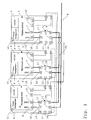
- control device arrangement is shown in FIG. Therein, three control units 1, 2, 3 configured redundantly with respect to the ESP (Electronic Stability Program) control function in a vehicle are interconnected in a TRM (Triple Modular Redundancy) arrangement.
- ESP Electronic Stability Program
- TRM Triple Modular Redundancy
- the three redundant control units 1, 2, 3 are connected via a first data bus 4 with other control units of the vehicle.
- the three redundant control units 1, 2, 3 are connected to one another via a second data bus 60.
- This data bus is used exclusively for the exchange of the result signals between the three redundantly designed control units 1, 2, 3.
- the first and second data buses 4, 60 are implemented as CAN (Controller Area Network) data buses.
- each of the three redundantly designed control units 1, 2, 3 has two bidirectional data bus connections 6, 7, wherein the data bus connection 6 serves the connection to the first data bus 4 and the data bus connection 7 to the connection to the second data bus 60.
- the redundant control units 1, 2, 3 have in addition to the arithmetic unit with processor and memory for performing the ESP control function in each case via a power supply unit 8 and a selection means. 9
- the voltage supply unit 8 of the redundant control units 1, 2, 3 has an input port 10. About this port 10, the power supply of the controller, so the controller itself can be switched off by means of a signal.
- control unit 1 By way of example, the mode of operation of the control device arrangement according to the invention in connection with the data bus switch 5 will now be explained on a control unit 1.
- the further control devices 2, 3 function equivalently.
- the control unit 1 processes input data which it receives via the first data bus 4 from further control devices, actuators, sensors, etc. connected to the data bus 4.
- these input data are the yaw rate, the speed, the engine speed and the acceleration of the vehicle.
- These input data are processed by the rules of the control unit 1 and output data generated. These output data are applied to the second data bus 60, where they are detected by the further control devices 2, 3. The control unit 1 in turn detects the output data of the further control devices 2, 3.
- the selection means 9 also called voter, serves to carry out a comparison of the own output data with the received output data of the further control devices 2, 3.
- the selection means which is implemented by software, is designed in this case so that temporal and magnitude deviations of the output data are allowed.
- the election process in the TRM system is as follows: If all three output data do not match, the system is shut down. If two output data match, there is a single error and the matching output data are adopted as the correct starting date. If all three output data match, there is no error. Each starting date can be adopted as a size.
- the voting means 9 assigns to the transmitted output signals of the further control devices 2, 3 in each case an evaluation signal.
- control unit 1 Only an excellent A of the three redundant control units 1, 2, 3, here the control unit 1, is the control unit which sends its output signal after the election process on the first data bus 4 for command transmission to the other connected to the data bus 4 control units. If it has been determined after an election process that the control unit 1 is working incorrectly, one of the further control units 2, 3 assumes the task of sending the output date determined after the selection process to the first data bus 4. For this purpose, a parameter is stored in the selection means, which indicates which control unit of the redundantly designed control units 1-3 assumes this function.
- the control device 1 in FIG. 1 has two output ports 11, 12, which serve to transmit the evaluation signals of the output data of the further redundant control devices 2, 3. These output ports 11, 12 are connected via a respective signal line to the input ports 13, 14 of the respective data bus switch 5 of the further control devices 2, 3. The evaluation signal is transmitted to the respective data bus circuit breakers of the control units 2, 3 via this signal line.
- the data bus circuit breaker 5 has in each case two bidirectional data bus connections 15, 16 or 17, 18 connected via switches.
- the data bus connections 15-18 are connected in such a way that they establish or disconnect the connection of the control device 1 to the first data bus 4 via the connections 15, 16 and to the second data bus 60 via the connections 17, 18.
- the data bus switch 5 additionally has a logic circuit whose input signals are formed by the input ports 13, 14 of the data bus switch 5. At the input ports 13, 14 of the data bus circuit breaker 5, the evaluation signals of the further control devices 2, 3 are transmitted via the output signals of the control device 1.
- the logic circuit of the data bus switch 5 consists of an OR gate.
- the evaluation signals arriving at the input ports 13, 14 have either the value of zero for non-compliance or the value of one for coincidence of the output signals.
- the data bus disconnects in the event of an error, the connection between the data bus terminals 15, 16 and 17, 18.
- the control unit 1 in the event of an error of the communication via the first and second data bus 4, 60 separated.
- the data bus switch has an output port 19. This output port 19 of the control unit 1 is connected via a signal line to the input port 10 of the power supply of the control unit 1.
- the data bus switch 5 additionally sends a signal via the output port 19 of the data bus switch 5 to the input port 10 of the voltage supply 8, which switches off the power supply 8 of the control device 1 and thus the control device 1 itself.
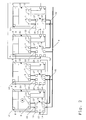
- FIG. 2 shows a further embodiment of the control device arrangement according to the invention.
- four ECUs 20-23 redundantly configured with respect to the ESP (Electronic Stability Program) control function in a vehicle are interconnected in a duo-duplex arrangement.
- the four redundant controllers 20-22 in FIG. 2 are connected via a first data bus 4 to further control devices of the vehicle.
- duo-duplex arrangement requires a second independent data bus for the respective channel.
- the two second data buses 61, 62 serve exclusively to exchange the result signals between in each case two of the four redundantly designed control units 20-23.
- the data buses 4, 61, 62 are designed as CAN (Controller Area Network) data bus.
- the selection means 9 of the control unit 20 in one pair of the duo-duplex arrangement performs comparison operations only with respect to result signals of the another control unit 21.
- the controller 20 provides only an evaluation signal, which is transmitted by means of a signal line from the output port 12 to the input port 13 of the data bus switch 5 of the controller 21 to the data bus switch.
- the data bus circuit breaker 5 of the controller 20 receives via the input port 13, the evaluation signal of the controller 21 with respect to the output data of the controller 20.
- the logic circuit of the data bus switch 5 has as an input signal the evaluation signal on the input port 13.
- the second input signal from the second input port 14 is fixed.
- the value "zero" is defined as the second input signal.
- the data bus circuit breaker 5 of the control unit 20 separates the controller 20 from the communication to the first and second data bus 4, 61 in the event of a fault, as explained above.
- the power supply 8 of the controller 20 is switched off. If a control unit of a control unit pair 20, 21 or 22, 23 fails, the pair 20, 21 or 22, 23 is switched off. This is easy to see since, for example, in the switching off of the first control unit 20 of the pair, the second control unit 21 would not receive an output signal of a redundantly executed control unit via the second data bus 61 and thus would not be able to compare its output signal.
- the control unit 20 is the selected control unit A, which, if there is no error, transmits the result signal to the first data bus 4. If the control unit 20 fails, the pair 20, 21 is switched off. Since the control unit pair 22, 23 monitors via the first data bus 4 whether the control unit 20 sends the output data to the data bus 4, one of the two control units 22, 23 assumes the function of sending the result signal to the data bus 4.
- the logic circuit of the data bus switch 5 is executed in hardware.
- the switchable connection between ports 15, 16 or 17, 18 is designed as a logic module switch.
- the switchable connection can also be designed as a relay switch.
- the bidirectional ports 15-18 may be configured such that, for example, the twisted pair cable of the CAN data bus is looped through or that in each case a corresponding transceiver unit such as a CAN transceiver is attached to the data bus ports 15-18.
- the data buses 4, 60-62 are designed as CAN data buses. However, these could also be embodied as optical data buses such as D2B or MOST or as TTP, LIN, FlexRay, Firewire, etc.
- the control device arrangement according to the invention has a second data bus 60-62 for internal communication between the control devices 1-3, 20-23 configured redundantly for a control function. This is chosen so that the first CAN data bus 4, which ensures the communication with the other control units in the vehicle, is generally already busy in its bandwidth and no additional data traffic, as he used for internal communication between the redundant ECUs 1- 3, 20-23 is needed, more is possible.
- the second data bus 60-62 is no longer necessary.
- the communication between the control units of the vehicle and the communication between the redundant control units 1-3, 20-23 then runs only on the first data bus. 4
- the controller assembly is ideal for asynchronous communication of the controllers.
- the redundantly designed control devices 1-3, 20-23 can come from different manufacturers or be based on different hardware.
- the selection means 9 of the redundant control units 1-3, 20-23 can use different election processes to obtain the evaluation signal.
Abstract
Claims (11)
- Arrangement d'appareils de commande comprenant plusieurs appareils de commande (1-3, 20-23) mis en réseau par le biais d'un premier bus de données (4), lesquels- commandent les composants d'un moyen de communication et- échangent entre eux des informations par le biais du premier bus de données (4),- des appareils de commande (1-3 ; 20-23) conçus de manière redondante par rapport à une fonction de commande étant présents et- un sectionneur de bus de données (5) étant à chaque fois associé aux appareils de commande (1-3 ; 20-23) conçus de manière redondante, lequel rend passant ou interrompt le bus de données (4) en fonction d'un signal d'évaluation de telle sorte que la communication sur le bus de données soit activée ou désactivée, caractérisé en ce que- chacun de ces sectionneurs de bus de données (5) est relié avec une ligne de signal d'au moins un appareil de commande (1-3; 20-23) redondant supplémentaire, que- un appareil de commande (2, 3 ; 21 ; 23) redondant supplémentaire transmet un signal d'évaluation au sectionneur de bus de données (5) associé à un premier appareil de commande (1 ; 20 ; 22) redondant, le signal d'évaluation étant le résultat d'un contrôle du fonctionnement de l'appareil de commande (2, 3 ; 21 ; 23) redondant supplémentaire par rapport au premier appareil de commande (1 ; 20 ; 22) redondant et- le sectionneur de bus de données (5) du premier appareil de commande (1 ; 20 ; 22) redondant interrompt le bus de données (4) en fonction du résultat d'un circuit logique, au moins un signal d'entrée du circuit logique étant formé par l'au moins un signal d'évaluation.
- Arrangement d'appareils de commande selon la revendication 1, caractérisé en ce que les appareils de commande (1-3 ; 20-23) conçus de manière redondante par rapport à une fonction de commande sont reliés par le biais d'un deuxième bus de données (60-62) pour échanger les signaux de résultat de la fonction de commande.
- Arrangement d'appareils de commande selon la revendication 1 ou 2, caractérisé en ce que l'émission du signal de résultat de la fonction de commande sur le premier bus de données (4) s'effectue au moyen d'un appareil de commande (A) pouvant être prédéfini parmi les appareils de commande (1-3 ; 20-23) conçus de manière redondante par rapport à une fonction de commande.
- Arrangement d'appareils de commande selon la revendication 3, caractérisé en ce que l'appareil de commande (A) pouvant être prédéfini peut être défini au moyen d'un paramètre dans les appareils de commande (1-3 ; 20-23) conçus de manière redondante par rapport à une fonction de commande.
- Arrangement d'appareils de commande selon la revendication 4, caractérisé en ce que le paramètre représente la hiérarchie de substitution pour l'appareil de commande (A) parmi les appareils de commande (1-3; 20-23) remplaçant les appareils de commande conçus de manière redondante par rapport à une fonction de commande.
- Arrangement d'appareils de commande selon les revendications 2 à 5, caractérisé en ce que les appareils de commande (1-3 ; 20-23) conçus de manière redondante par rapport à une fonction de commande disposent d'une fonction de passerelle de sorte qu'en cas d'interruption d'un bus de données (4 ; 60-62), l'échange de données est maintenu au moyen de la fonctionnalité de passerelle par le biais de l'autre (60-62 ; 4) bus de données.
- Arrangement d'appareils de commande selon les revendications 1 à 6, caractérisé en ce que- le sectionneur de bus de données (5) présente au moins un port d'entrée (13, 14) pour le signal d'évaluation d'au moins un appareil de commande supplémentaire (2, 3 ; 21 ; 23) et- la liaison pour le bus de données (4) peut être commutée en étant commandée au moyen d'un circuit logique,- au moins un signal d'évaluation formant un signal d'entrée du circuit logique afin de, en fonction du résultat du circuit logique,- couper la communication de l'appareil de commande associé (1 ; 20 ; 22) vers le premier bus de données (4).
- Arrangement d'appareils de commande selon la revendication 7, caractérisé en ce que- le sectionneur de bus de données (5) présente un port de sortie (19), lequel est relié avec l'alimentation électrique (8) de l'appareil de commande associé (1 ; 20 ; 22) par le biais d'une ligne de signal et- qu'en fonction du résultat du circuit logique, un signal de commande est envoyé par le biais de la ligne de commande, lequel déconnecte l'appareil de commande associé (1; 20; 22) de l'alimentation électrique (8).
- Arrangement d'appareils de commande selon la revendication 7 ou 8, caractérisé en ce que la liaison commutable est réalisée sous la forme d'un commutateur à relais ou d'un composant logique.
- Sectionneur de bus de données (5) comprenant une liaison électrique commutable pour un bus de données (4, 60-62),- le bus de données (4, 60-62) étant relié par une unité d'émission/réception d'un appareil de commande (1-3 ; 20-22) associé à l'unité d'émission/réception avec une borne de bus de données (15, 17) du sectionneur de bus de données (5),caractérisé en ce que- le sectionneur de bus de données (5) présente au moins un port d'entrée (13, 14) pour le signal d'évaluation d'au moins un appareil de commande supplémentaire (2, 3 ; 21 ; 23),- présente un port de sortie (19), lequel est relié avec l'alimentation électrique (8) de l'appareil de commande associé (1 ; 20 ; 22) par le biais d'une ligne de signal et- la liaison est commutable au moyen d'un circuit logique,- au moins un signal d'évaluation formant un signal d'entrée du circuit logique afin de, en fonction du résultat du circuit logique,- couper la communication de l'appareil de commande (1 ; 20 ; 22) vers le bus de données (4, 60-62) et- envoyer un signal de commande par le biais de la ligne de commande, lequel déconnecte l'appareil de commande (1 ; 20 ; 22) de l'alimentation électrique (8).
- Sectionneur de bus de données selon la revendication 10, caractérisé en ce que la liaison commutable est réalisée sous la forme d'un commutateur à relais ou d'un composant logique.
Applications Claiming Priority (3)
| Application Number | Priority Date | Filing Date | Title |
|---|---|---|---|
| DE10243713A DE10243713B4 (de) | 2002-09-20 | 2002-09-20 | Redundante Steuergeräteanordnung |
| DE10243713 | 2002-09-20 | ||
| PCT/EP2003/009642 WO2004029737A1 (fr) | 2002-09-20 | 2003-08-30 | Systeme de dispositifs de commande redondant |
Publications (2)
| Publication Number | Publication Date |
|---|---|
| EP1540428A1 EP1540428A1 (fr) | 2005-06-15 |
| EP1540428B1 true EP1540428B1 (fr) | 2006-10-04 |
Family
ID=31969318
Family Applications (1)
| Application Number | Title | Priority Date | Filing Date |
|---|---|---|---|
| EP03747947A Expired - Lifetime EP1540428B1 (fr) | 2002-09-20 | 2003-08-30 | Systeme de dispositifs de commande redondant |
Country Status (5)
| Country | Link |
|---|---|
| US (1) | US7483778B2 (fr) |
| EP (1) | EP1540428B1 (fr) |
| JP (1) | JP3965410B2 (fr) |
| DE (2) | DE10243713B4 (fr) |
| WO (1) | WO2004029737A1 (fr) |
Families Citing this family (41)
| Publication number | Priority date | Publication date | Assignee | Title |
|---|---|---|---|---|
| DE10259546A1 (de) * | 2002-12-19 | 2004-07-01 | Robert Bosch Gmbh | Vorrichtung zur drahtlosen Übertragung eines Auslösesignals |
| EP1758778B1 (fr) * | 2004-05-13 | 2012-02-29 | Haldex Brake Products Aktiebolag | Reseau de commande et d'alimentation pour systeme de freinage de vehicule |
| JP5013668B2 (ja) * | 2004-11-19 | 2012-08-29 | 株式会社デンソー | 車両用制御システム |
| DE102005034161B3 (de) * | 2005-07-21 | 2006-10-12 | Siemens Ag | Elektronische Vorrichtung |
| ES2436609T3 (es) * | 2006-05-16 | 2014-01-03 | Saab Ab | Nodo de bus de datos de tolerancia de fallos en un sistema distribuido |
| KR100871857B1 (ko) * | 2007-06-11 | 2008-12-03 | 성균관대학교산학협력단 | 차량 내부의 네트워크 시스템 및 그 제어방법 |
| DE102007033885A1 (de) * | 2007-07-20 | 2009-01-22 | Siemens Ag | Verfahren zur transparenten Replikation einer Softwarekomponente eines Softwaresystems |
| DE102007046706A1 (de) * | 2007-09-28 | 2009-04-16 | Autoliv Development Ab | Steuervorrichtung für Fahrzeuge |
| US7941253B1 (en) * | 2007-11-27 | 2011-05-10 | Brunswick Corporation | Marine propulsion drive-by-wire control system with shared isolated bus |
| US8213706B2 (en) * | 2008-04-22 | 2012-07-03 | Honeywell International Inc. | Method and system for real-time visual odometry |
| US8130773B2 (en) * | 2008-06-25 | 2012-03-06 | Honeywell International Inc. | Hybrid topology ethernet architecture |
| FR2934693B1 (fr) | 2008-07-30 | 2011-03-25 | Airbus France | Systeme aeronautique embarque a reconfiguration dynamique, procede associe et aeronef embarquant un tel systeme. |
| US8149554B2 (en) * | 2008-11-18 | 2012-04-03 | Rockwell Automation Technologies, Inc. | Apparatus for fault tolerant digital inputs |
| US8441766B2 (en) * | 2008-11-18 | 2013-05-14 | Rockwell Automation Technologies, Inc. | Apparatus for fault tolerant digital outputs |
| DE102008060984A1 (de) * | 2008-12-06 | 2010-06-10 | Dr. Ing. H.C. F. Porsche Aktiengesellschaft | Verfahren zum Schutz vor Außeneingriffen in ein Master/Slave-Bussystem und Master/Slave-Bussystem |
| DE102009005266A1 (de) | 2009-01-20 | 2010-07-22 | Continental Teves Ag & Co. Ohg | Anbindung eines Kommunikationscontrollers in Sicherheitsarchitekturen |
| FR2943037B1 (fr) * | 2009-03-11 | 2012-09-21 | Airbus France | Systeme de commande d'aeronef a architecture modulaire integre. |
| US8156371B2 (en) * | 2009-06-16 | 2012-04-10 | Honeywell International Inc. | Clock and reset synchronization of high-integrity lockstep self-checking pairs |
| DE102011082969B4 (de) * | 2011-09-19 | 2015-04-30 | Siemens Aktiengesellschaft | Verfahren zum Betreiben eines Kommunikationsnetzwerkes und Netzwerkanordnung |
| JP6227239B2 (ja) * | 2011-11-16 | 2017-11-08 | ナブテスコ株式会社 | 航空機制御装置及び航空機制御システム |
| DE102012209108B4 (de) * | 2012-05-30 | 2014-05-15 | Siemens Aktiengesellschaft | Netzwerkeinrichtung, Netzwerkanordnung und Verfahren zum Betreiben einer Netzwerkanordnung |
| DE102012106652A1 (de) * | 2012-07-23 | 2014-01-23 | Endress + Hauser Gmbh + Co. Kg | Feldgerät zur Bestimmung oder Überwachung einer Prozessgröße in der Automatisierungstechnik |
| US9266518B2 (en) * | 2013-11-08 | 2016-02-23 | GM Global Technology Operations LLC | Component control system for a vehicle |
| KR101704787B1 (ko) * | 2014-12-31 | 2017-02-22 | 주식회사 효성 | 제어기의 이중화 시스템 |
| DE102015201278B4 (de) | 2015-01-26 | 2016-09-29 | Continental Automotive Gmbh | Steuersystem |
| WO2016155763A1 (fr) * | 2015-03-30 | 2016-10-06 | Volvo Truck Corporation | Procédé et agencement de fourniture de redondance dans un système de commande électrique de véhicule |
| JP6777641B2 (ja) | 2015-09-29 | 2020-10-28 | 日立オートモティブシステムズ株式会社 | 監視システム及び車両用制御装置 |
| DE102015218898A1 (de) * | 2015-09-30 | 2017-03-30 | Robert Bosch Gmbh | Verfahren zur redundanten Verarbeitung von Daten |
| DE102016015616B4 (de) * | 2016-12-28 | 2021-12-30 | Bachmann Gmbh | Modul-System mit Busanbindung und Direkt-Drahtverbindung |
| JP6817410B2 (ja) | 2017-02-23 | 2021-01-20 | 本田技研工業株式会社 | 車両用制御システムおよび制御方法 |
| CN110300691B (zh) | 2017-02-23 | 2022-08-09 | 本田技研工业株式会社 | 车辆用控制系统 |
| JPWO2018154862A1 (ja) | 2017-02-23 | 2019-12-12 | 本田技研工業株式会社 | 車両用制御システムおよび制御方法 |
| US10394241B2 (en) * | 2017-06-15 | 2019-08-27 | GM Global Technology Operations LLC | Multi-stage voting control |
| US10647329B2 (en) | 2017-12-12 | 2020-05-12 | Uatc, Llc | Disengaging autonomous control of vehicle |
| KR102482143B1 (ko) * | 2018-01-30 | 2022-12-29 | 에이치엘만도 주식회사 | Ecu 및 ecu 동작 방법 |
| KR102111295B1 (ko) | 2018-02-05 | 2020-05-15 | 주식회사 만도 | 리던던트 구조 기반의 차량 제어 장치 및 방법 |
| EP3761568B1 (fr) * | 2019-07-01 | 2023-05-31 | Volvo Car Corporation | Procédé de commande de communication sur un bus du réseau d'interconnexion local |
| CN112735310B (zh) * | 2020-12-22 | 2022-08-02 | 北京市轨道交通运营管理有限公司 | 一种顶棚导向显示板的测试系统及高精度测试方法 |
| DE102021112121A1 (de) | 2021-05-10 | 2022-11-10 | Schaeffler Technologies AG & Co. KG | Verfahren zur Datenübertragung innerhalb eines Fahrzeugkontrollsystems, Kontrollsystem und Kraftfahrzeug |
| EP4116620A1 (fr) * | 2021-07-09 | 2023-01-11 | Leuze electronic GmbH + Co. KG | Dispositif de surveillance et procédé de fonctionnement d'un dispositif de surveillance |
| EP4187858A1 (fr) | 2021-11-29 | 2023-05-31 | KNORR-BREMSE Systeme für Nutzfahrzeuge GmbH | Unité de commande secondaire pour un véhicule doté d'une unité de commande primaire et d'un chemin de transmission de données |
Family Cites Families (16)
| Publication number | Priority date | Publication date | Assignee | Title |
|---|---|---|---|---|
| US4621327A (en) * | 1984-06-13 | 1986-11-04 | Nartron Corporation | Electronic power steering method and apparatus |
| US4622667A (en) * | 1984-11-27 | 1986-11-11 | Sperry Corporation | Digital fail operational automatic flight control system utilizing redundant dissimilar data processing |
| DE3638947C2 (de) * | 1986-11-14 | 1995-08-31 | Bosch Gmbh Robert | Verfahren zur Synchronisation von Rechnern eines Mehrrechnersystems und Mehrrechnersystem |
| DE4122016A1 (de) * | 1991-07-03 | 1993-01-21 | Hella Kg Hueck & Co | Antiblockierregelsystem |
| US5493497A (en) | 1992-06-03 | 1996-02-20 | The Boeing Company | Multiaxis redundant fly-by-wire primary flight control system |
| CA2137157A1 (fr) | 1992-06-12 | 1993-12-23 | Edward R. Sederlund | Interface furtive pour ordinateurs de controle de processus |
| JPH06348524A (ja) | 1993-06-10 | 1994-12-22 | Hitachi Ltd | 多重化制御装置 |
| US5515282A (en) * | 1994-04-25 | 1996-05-07 | The Boeing Company | Method and apparatus for implementing a databus voter to select flight command signals from one of several redundant asynchronous digital primary flight computers |
| DE4439060A1 (de) | 1994-11-02 | 1996-05-09 | Teves Gmbh Alfred | Mikroprozessoranordnung für ein Fahrzeug-Regelungssystem |
| DE19612423A1 (de) * | 1996-03-28 | 1997-10-02 | Siemens Ag | Steuer- und Sicherheitssystem für Krananlagen |
| DE19631309A1 (de) * | 1996-08-02 | 1998-02-05 | Teves Gmbh Alfred | Mikroprozessoranordnung für ein Fahrzeug-Regelungssystem |
| DE19915253A1 (de) * | 1999-04-03 | 2000-10-05 | Bosch Gmbh Robert | Verfahren und Vorrichtung zum Betreiben eines verteilten Steuersystems in einem Fahrzeug |
| DE19944939C1 (de) * | 1999-09-20 | 2001-08-30 | Mannesmann Vdo Ag | Steuergerät für ein Kraftfahrzeug |
| DE19947251A1 (de) * | 1999-09-30 | 2001-05-31 | Bosch Gmbh Robert | Verfahren und Vorrichtung zur Steuerung von Prozessen in Verbindung mit einem Antrieb |
| DE10002519C1 (de) | 2000-01-21 | 2001-04-05 | Siemens Ag | Verfahren zur Verhinderung von Fehlfunktionen in einem signalverarbeitenden System und Prozessorsystem |
| EP1349759A1 (fr) * | 2001-01-12 | 2003-10-08 | DaimlerChrysler AG | Dispositif de controle de moyens detecteurs agences dans un vehicule |
-
2002
- 2002-09-20 DE DE10243713A patent/DE10243713B4/de not_active Expired - Fee Related
-
2003
- 2003-08-30 JP JP2004538854A patent/JP3965410B2/ja not_active Expired - Fee Related
- 2003-08-30 WO PCT/EP2003/009642 patent/WO2004029737A1/fr active IP Right Grant
- 2003-08-30 DE DE50305291T patent/DE50305291D1/de not_active Expired - Lifetime
- 2003-08-30 EP EP03747947A patent/EP1540428B1/fr not_active Expired - Lifetime
- 2003-08-30 US US10/513,826 patent/US7483778B2/en not_active Expired - Fee Related
Also Published As
| Publication number | Publication date |
|---|---|
| DE10243713B4 (de) | 2006-10-05 |
| JP3965410B2 (ja) | 2007-08-29 |
| DE10243713A1 (de) | 2004-04-01 |
| US20060116803A1 (en) | 2006-06-01 |
| WO2004029737A1 (fr) | 2004-04-08 |
| JP2005521182A (ja) | 2005-07-14 |
| EP1540428A1 (fr) | 2005-06-15 |
| US7483778B2 (en) | 2009-01-27 |
| DE50305291D1 (de) | 2006-11-16 |
Similar Documents
| Publication | Publication Date | Title |
|---|---|---|
| EP1540428B1 (fr) | Systeme de dispositifs de commande redondant | |
| EP1763454B1 (fr) | Systeme redondant de bus de donnees | |
| EP0092719B1 (fr) | Disposition pour le couplage d'unités de traitement numérique | |
| EP3661819B1 (fr) | Système de commande pour véhicule automobile, véhicule automobile, procédé de commande d'un véhicule automobile, produit programme informatique et support lisible par ordinateur | |
| DE4416795C2 (de) | Redundant konfigurierbares Übertragungssystem zum Datenaustausch und Verfahren zu dessen Betrieb | |
| EP3398069B1 (fr) | Dispositif de controle embarqué destiné à l'éxécution d' une opération functionelle redondante et véhicule le comportant | |
| DE102017218395A1 (de) | Verfahren zur fehlerrobusten Regelung von hochautomatisierten Fahrzeugen | |
| DE102008009652A1 (de) | Überwachungseinrichtung und Überwachungsverfahren für einen Sensor, sowie Sensor | |
| EP2297619B1 (fr) | Système de surveillance | |
| DE102018220605A1 (de) | Kraftfahrzeugnetzwerk und Verfahren zum Betreiben eines Kraftfahrzeugnetzwerks | |
| EP2862093B1 (fr) | Système de capteurs destiné à une architecture électrique/électronique et architecture électrique/électronique correspondante pour un véhicule | |
| DE4416879B4 (de) | Steuergerät mit Mitteln zur Umschaltung zwischen zwei Datenleitungen | |
| WO2003007554A1 (fr) | Elements reseau destine a un reseau optique ayant tune fonction de securite, en particulier a un reseau optique a topologie annulaire | |
| DE60319175T2 (de) | Datenübertragungssystem im Fahrzeug mit redundanten Verbindungen | |
| DE102011115318B4 (de) | Flugsteuerungssystem | |
| DE102010038459A1 (de) | Sicherheitssystem | |
| DE102016203966A1 (de) | Steuereinheit und Verfahren zur Ansteuerung von zumindest einem Aktuator eines Fahrzeugs | |
| DE19944132A1 (de) | System zur prozessgesteuerten Übertragung von elektrischen Signalen und elektrischer Energie innerhalb eines militärischen Fahrzeugs | |
| EP3281365B1 (fr) | Dispositif d'extension d'interface pour un dispositif réseau et procédé de fonctionnement d'un dispositif d'extension d'interface | |
| EP3567809A2 (fr) | Système de commande, de régulation et / ou de surveillance d'un aéronef | |
| DE102018203887B4 (de) | Steuergerät für ein Mehrspannungsbordnetz eines Fahrzeugs und Mehrspannungsbordnetz | |
| DE102005001421A1 (de) | Datenbustrennschalter und zugehörige Steuergeräteanordnung | |
| EP1675310B1 (fr) | Procédé de communication des données et système bus des données pour automobile | |
| DE102020112955B4 (de) | Reiheneinbaugerät, Automatisierungssystem und Verfahren zur Prozessautomation | |
| WO2011113405A1 (fr) | Groupement d'appareils de commande |
Legal Events
| Date | Code | Title | Description |
|---|---|---|---|
| PUAI | Public reference made under article 153(3) epc to a published international application that has entered the european phase |
Free format text: ORIGINAL CODE: 0009012 |
|
| 17P | Request for examination filed |
Effective date: 20040331 |
|
| AK | Designated contracting states |
Kind code of ref document: A1 Designated state(s): AT BE BG CH CY CZ DE DK EE ES FI FR GB GR HU IE IT LI LU MC NL PT RO SE SI SK TR |
|
| RBV | Designated contracting states (corrected) |
Designated state(s): AT BE BG CH DE FR GB IT LI |
|
| GRAP | Despatch of communication of intention to grant a patent |
Free format text: ORIGINAL CODE: EPIDOSNIGR1 |
|
| RBV | Designated contracting states (corrected) |
Designated state(s): DE FR GB IT |
|
| RIN1 | Information on inventor provided before grant (corrected) |
Inventor name: ARMBRUSTER, MICHAEL Inventor name: SPIEGELBERG, GERNOT Inventor name: SULZMANN, ARMIN Inventor name: HEILMANN, HARRO Inventor name: SCHWARZHAUPT, ANDREAS Inventor name: ROOKS, OLIVER Inventor name: MAISCH, ANSGAR |
|
| GRAS | Grant fee paid |
Free format text: ORIGINAL CODE: EPIDOSNIGR3 |
|
| GRAA | (expected) grant |
Free format text: ORIGINAL CODE: 0009210 |
|
| AK | Designated contracting states |
Kind code of ref document: B1 Designated state(s): DE FR GB IT |
|
| PG25 | Lapsed in a contracting state [announced via postgrant information from national office to epo] |
Ref country code: IT Free format text: LAPSE BECAUSE OF FAILURE TO SUBMIT A TRANSLATION OF THE DESCRIPTION OR TO PAY THE FEE WITHIN THE PRESCRIBED TIME-LIMIT;WARNING: LAPSES OF ITALIAN PATENTS WITH EFFECTIVE DATE BEFORE 2007 MAY HAVE OCCURRED AT ANY TIME BEFORE 2007. THE CORRECT EFFECTIVE DATE MAY BE DIFFERENT FROM THE ONE RECORDED. Effective date: 20061004 |
|
| REG | Reference to a national code |
Ref country code: GB Ref legal event code: FG4D Free format text: NOT ENGLISH |
|
| GBT | Gb: translation of ep patent filed (gb section 77(6)(a)/1977) |
Effective date: 20061016 |
|
| REF | Corresponds to: |
Ref document number: 50305291 Country of ref document: DE Date of ref document: 20061116 Kind code of ref document: P |
|
| RAP2 | Party data changed (patent owner data changed or rights of a patent transferred) |
Owner name: DAIMLERCHRYSLER AG |
|
| EN | Fr: translation not filed | ||
| PLBE | No opposition filed within time limit |
Free format text: ORIGINAL CODE: 0009261 |
|
| STAA | Information on the status of an ep patent application or granted ep patent |
Free format text: STATUS: NO OPPOSITION FILED WITHIN TIME LIMIT |
|
| 26N | No opposition filed |
Effective date: 20070705 |
|
| PG25 | Lapsed in a contracting state [announced via postgrant information from national office to epo] |
Ref country code: FR Free format text: LAPSE BECAUSE OF FAILURE TO SUBMIT A TRANSLATION OF THE DESCRIPTION OR TO PAY THE FEE WITHIN THE PRESCRIBED TIME-LIMIT Effective date: 20070525 |
|
| PG25 | Lapsed in a contracting state [announced via postgrant information from national office to epo] |
Ref country code: FR Free format text: LAPSE BECAUSE OF FAILURE TO SUBMIT A TRANSLATION OF THE DESCRIPTION OR TO PAY THE FEE WITHIN THE PRESCRIBED TIME-LIMIT Effective date: 20061004 |
|
| PGFP | Annual fee paid to national office [announced via postgrant information from national office to epo] |
Ref country code: GB Payment date: 20100819 Year of fee payment: 8 |
|
| GBPC | Gb: european patent ceased through non-payment of renewal fee |
Effective date: 20110830 |
|
| PG25 | Lapsed in a contracting state [announced via postgrant information from national office to epo] |
Ref country code: GB Free format text: LAPSE BECAUSE OF NON-PAYMENT OF DUE FEES Effective date: 20110830 |
|
| PGFP | Annual fee paid to national office [announced via postgrant information from national office to epo] |
Ref country code: DE Payment date: 20141031 Year of fee payment: 12 |
|
| REG | Reference to a national code |
Ref country code: DE Ref legal event code: R119 Ref document number: 50305291 Country of ref document: DE |
|
| PG25 | Lapsed in a contracting state [announced via postgrant information from national office to epo] |
Ref country code: DE Free format text: LAPSE BECAUSE OF NON-PAYMENT OF DUE FEES Effective date: 20160301 |