EP1540428B1 - Redundant control unit arrangement - Google Patents
Redundant control unit arrangement Download PDFInfo
- Publication number
- EP1540428B1 EP1540428B1 EP03747947A EP03747947A EP1540428B1 EP 1540428 B1 EP1540428 B1 EP 1540428B1 EP 03747947 A EP03747947 A EP 03747947A EP 03747947 A EP03747947 A EP 03747947A EP 1540428 B1 EP1540428 B1 EP 1540428B1
- Authority
- EP
- European Patent Office
- Prior art keywords
- data bus
- control
- control device
- redundant
- control devices
- Prior art date
- Legal status (The legal status is an assumption and is not a legal conclusion. Google has not performed a legal analysis and makes no representation as to the accuracy of the status listed.)
- Expired - Lifetime
Links
- 238000011156 evaluation Methods 0.000 claims abstract description 26
- 238000004891 communication Methods 0.000 claims description 13
- 238000011990 functional testing Methods 0.000 abstract description 2
- 230000006870 function Effects 0.000 description 15
- 238000000034 method Methods 0.000 description 9
- 238000012545 processing Methods 0.000 description 6
- 230000002457 bidirectional effect Effects 0.000 description 3
- 238000011161 development Methods 0.000 description 3
- 238000010276 construction Methods 0.000 description 2
- 238000010586 diagram Methods 0.000 description 2
- 230000007257 malfunction Effects 0.000 description 2
- 230000001133 acceleration Effects 0.000 description 1
- 230000005540 biological transmission Effects 0.000 description 1
- 230000003750 conditioning effect Effects 0.000 description 1
- 230000009977 dual effect Effects 0.000 description 1
- 230000000694 effects Effects 0.000 description 1
- 238000004519 manufacturing process Methods 0.000 description 1
- 230000003287 optical effect Effects 0.000 description 1
- 238000000926 separation method Methods 0.000 description 1
- 230000001360 synchronised effect Effects 0.000 description 1
- 230000002123 temporal effect Effects 0.000 description 1
Images
Classifications
-
- G—PHYSICS
- G06—COMPUTING; CALCULATING OR COUNTING
- G06F—ELECTRIC DIGITAL DATA PROCESSING
- G06F11/00—Error detection; Error correction; Monitoring
- G06F11/07—Responding to the occurrence of a fault, e.g. fault tolerance
- G06F11/16—Error detection or correction of the data by redundancy in hardware
- G06F11/18—Error detection or correction of the data by redundancy in hardware using passive fault-masking of the redundant circuits
- G06F11/181—Eliminating the failing redundant component
-
- G—PHYSICS
- G05—CONTROLLING; REGULATING
- G05B—CONTROL OR REGULATING SYSTEMS IN GENERAL; FUNCTIONAL ELEMENTS OF SUCH SYSTEMS; MONITORING OR TESTING ARRANGEMENTS FOR SUCH SYSTEMS OR ELEMENTS
- G05B9/00—Safety arrangements
- G05B9/02—Safety arrangements electric
- G05B9/03—Safety arrangements electric with multiple-channel loop, i.e. redundant control systems
-
- G—PHYSICS
- G06—COMPUTING; CALCULATING OR COUNTING
- G06F—ELECTRIC DIGITAL DATA PROCESSING
- G06F11/00—Error detection; Error correction; Monitoring
- G06F11/07—Responding to the occurrence of a fault, e.g. fault tolerance
- G06F11/16—Error detection or correction of the data by redundancy in hardware
- G06F11/20—Error detection or correction of the data by redundancy in hardware using active fault-masking, e.g. by switching out faulty elements or by switching in spare elements
- G06F11/202—Error detection or correction of the data by redundancy in hardware using active fault-masking, e.g. by switching out faulty elements or by switching in spare elements where processing functionality is redundant
- G06F11/2023—Failover techniques
- G06F11/2028—Failover techniques eliminating a faulty processor or activating a spare
-
- G—PHYSICS
- G06—COMPUTING; CALCULATING OR COUNTING
- G06F—ELECTRIC DIGITAL DATA PROCESSING
- G06F11/00—Error detection; Error correction; Monitoring
- G06F11/07—Responding to the occurrence of a fault, e.g. fault tolerance
- G06F11/16—Error detection or correction of the data by redundancy in hardware
- G06F11/20—Error detection or correction of the data by redundancy in hardware using active fault-masking, e.g. by switching out faulty elements or by switching in spare elements
- G06F11/202—Error detection or correction of the data by redundancy in hardware using active fault-masking, e.g. by switching out faulty elements or by switching in spare elements where processing functionality is redundant
- G06F11/2038—Error detection or correction of the data by redundancy in hardware using active fault-masking, e.g. by switching out faulty elements or by switching in spare elements where processing functionality is redundant with a single idle spare processing component
-
- B—PERFORMING OPERATIONS; TRANSPORTING
- B60—VEHICLES IN GENERAL
- B60T—VEHICLE BRAKE CONTROL SYSTEMS OR PARTS THEREOF; BRAKE CONTROL SYSTEMS OR PARTS THEREOF, IN GENERAL; ARRANGEMENT OF BRAKING ELEMENTS ON VEHICLES IN GENERAL; PORTABLE DEVICES FOR PREVENTING UNWANTED MOVEMENT OF VEHICLES; VEHICLE MODIFICATIONS TO FACILITATE COOLING OF BRAKES
- B60T2270/00—Further aspects of brake control systems not otherwise provided for
- B60T2270/40—Failsafe aspects of brake control systems
- B60T2270/404—Brake-by-wire or X-by-wire failsafe
-
- B—PERFORMING OPERATIONS; TRANSPORTING
- B60—VEHICLES IN GENERAL
- B60T—VEHICLE BRAKE CONTROL SYSTEMS OR PARTS THEREOF; BRAKE CONTROL SYSTEMS OR PARTS THEREOF, IN GENERAL; ARRANGEMENT OF BRAKING ELEMENTS ON VEHICLES IN GENERAL; PORTABLE DEVICES FOR PREVENTING UNWANTED MOVEMENT OF VEHICLES; VEHICLE MODIFICATIONS TO FACILITATE COOLING OF BRAKES
- B60T2270/00—Further aspects of brake control systems not otherwise provided for
- B60T2270/40—Failsafe aspects of brake control systems
- B60T2270/413—Plausibility monitoring, cross check, redundancy
-
- B—PERFORMING OPERATIONS; TRANSPORTING
- B60—VEHICLES IN GENERAL
- B60T—VEHICLE BRAKE CONTROL SYSTEMS OR PARTS THEREOF; BRAKE CONTROL SYSTEMS OR PARTS THEREOF, IN GENERAL; ARRANGEMENT OF BRAKING ELEMENTS ON VEHICLES IN GENERAL; PORTABLE DEVICES FOR PREVENTING UNWANTED MOVEMENT OF VEHICLES; VEHICLE MODIFICATIONS TO FACILITATE COOLING OF BRAKES
- B60T2270/00—Further aspects of brake control systems not otherwise provided for
- B60T2270/82—Brake-by-Wire, EHB
-
- G—PHYSICS
- G06—COMPUTING; CALCULATING OR COUNTING
- G06F—ELECTRIC DIGITAL DATA PROCESSING
- G06F11/00—Error detection; Error correction; Monitoring
- G06F11/07—Responding to the occurrence of a fault, e.g. fault tolerance
- G06F11/16—Error detection or correction of the data by redundancy in hardware
- G06F11/1629—Error detection by comparing the output of redundant processing systems
- G06F11/1633—Error detection by comparing the output of redundant processing systems using mutual exchange of the output between the redundant processing components
-
- G—PHYSICS
- G06—COMPUTING; CALCULATING OR COUNTING
- G06F—ELECTRIC DIGITAL DATA PROCESSING
- G06F11/00—Error detection; Error correction; Monitoring
- G06F11/07—Responding to the occurrence of a fault, e.g. fault tolerance
- G06F11/16—Error detection or correction of the data by redundancy in hardware
- G06F11/18—Error detection or correction of the data by redundancy in hardware using passive fault-masking of the redundant circuits
- G06F11/182—Error detection or correction of the data by redundancy in hardware using passive fault-masking of the redundant circuits based on mutual exchange of the output between redundant processing components
-
- G—PHYSICS
- G06—COMPUTING; CALCULATING OR COUNTING
- G06F—ELECTRIC DIGITAL DATA PROCESSING
- G06F11/00—Error detection; Error correction; Monitoring
- G06F11/07—Responding to the occurrence of a fault, e.g. fault tolerance
- G06F11/16—Error detection or correction of the data by redundancy in hardware
- G06F11/20—Error detection or correction of the data by redundancy in hardware using active fault-masking, e.g. by switching out faulty elements or by switching in spare elements
- G06F11/202—Error detection or correction of the data by redundancy in hardware using active fault-masking, e.g. by switching out faulty elements or by switching in spare elements where processing functionality is redundant
- G06F11/2048—Error detection or correction of the data by redundancy in hardware using active fault-masking, e.g. by switching out faulty elements or by switching in spare elements where processing functionality is redundant where the redundant components share neither address space nor persistent storage
Definitions
- the invention relates to a control device arrangement having a plurality of controllers networked via a first data bus and a data bus circuit breaker.
- a redundantly designed system is a system in which a component, for example a microprocessor, is present multiple times and the same function is performed on these components that are present in multiple places. This means, in particular, that the same input data is processed by the components and the same output data is generated, wherein the output data can be assigned to the components for evaluation purposes.
- a component for example a microprocessor
- TRM Triple Modular Redundancy
- duo-duplex duo-duplex
- TRM system also called a 2-out-of-3 system
- three redundant components are coupled in such a way that a faulty component can be detected and its effect on the environment is prevented.
- duo-duplex system also called dual self-checking pair system
- two redundant components are combined to form a channel, whereby the malfunction of a component can be detected within a channel. If the malfunction of a component is detected, the corresponding channel is switched off.
- a processing system is known in an aircraft wire-line control system wherein each of a plurality of redundant asynchronous primary flight computers generates command signals, wherein at least one control surface of the aircraft is controlled by a plurality of actuators.
- the processing system controls the flight command signals transmitted to the actuators and includes a plurality of selectors, each selector being connected to a primary flight computer and one or more actuators for receiving the flight command signals from all primary flight computers, and selecting means for acting in accordance with a predetermined one Has election algorithm to transmit a selected flight signal.
- DE 196 31 309 A1 discloses a microprocessor arrangement for a vehicle control system which has a plurality of redundantly designed microprocessor systems connected to one another by bus systems.
- the data processing in the microprocessors serves control systems such as anti-lock and / or Traction control and the input signal conditioning.
- the symmetrically redundant output and / or intermediate results of the data processing are compared. In case of deviation, the relevant system is switched off.
- the data processing in these microprocessor systems is compared with the results of a simplified data processing and checked for plausibility. In the case of discrepancies, the control system can be temporarily maintained for functionally important data that are not "safety-critical".
- Redundant system function of a means of transport are generally implemented via a plurality of microprocessors which are accommodated on a printed circuit board.
- This implementation of redundant systems has the advantage of short and fast switching paths between the microprocessors.
- the disadvantage is that this implementation brings very high development costs and development times. This is particularly disadvantageous in the automotive sector, since today there are always shorter development times required for the generation of new models.
- redundant systems in the automotive sector should be composed of components that are already on the market and need only be minimally adapted to be part of a redundant system.
- already available on the market control units are available as components.
- each data bus circuit breaker with a signal line is at least one connected to another redundant control unit.
- Another redundant controller transmits an evaluation signal to the first redundant controller associated data bus switch, the evaluation signal is the result of a functional test of the other redundant controller with respect to the first redundant controller.
- the data bus switch of the first redundant controller interrupts the data bus depending on the result of a logic circuit, wherein at least one input signal of the logic circuit is formed by the at least one evaluation signal.
- control device arrangement has the advantage that control devices of any manufacturer can be used for the construction of a redundant arrangement.
- a further advantage is that the control unit shutdown or the separation from the data bus is independent of the dialing method used on the redundant control unit.
- the voting or voting process in the redundant control unit for evaluating the other redundant control units is independent of the selected hardware or Sorftware and can be changed individually. Important is only the final evaluation signal, which must be transmitted to the data bus circuit breaker of the relevant evaluated redundant control unit.
- the data bus circuit breaker can be developed independently of the control unit since it does not require any functional parts from the control unit, nor does the control unit require functional components from the data bus circuit breaker.
- control device arrangement and of the data bus circuit breaker is advantageous, whereby a fast and cost-effective production is ensured.
- control device arrangement is based on a smallest unit of two controllers which are redundant with regard to a control function, the controller arrangement can be extended by further controllers redundant with respect to this control function. This makes it easy to map TRM and DuoDuplex devices.
- the control device arrangement which has a first and second data bus, has the advantage that when a data bus is interrupted, this interruption is bypassed via a gateway circuit. This can be a quick remedy, for example, for a data bus short or a data bus cable break.
- a further advantage of the controller arrangement with the second additional data bus is that the first data bus, via which the communication with the further control devices of the means of transport is carried out, is not burdened with additional data traffic.
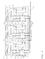
- control device arrangement is shown in FIG. Therein, three control units 1, 2, 3 configured redundantly with respect to the ESP (Electronic Stability Program) control function in a vehicle are interconnected in a TRM (Triple Modular Redundancy) arrangement.
- ESP Electronic Stability Program
- TRM Triple Modular Redundancy
- the three redundant control units 1, 2, 3 are connected via a first data bus 4 with other control units of the vehicle.
- the three redundant control units 1, 2, 3 are connected to one another via a second data bus 60.
- This data bus is used exclusively for the exchange of the result signals between the three redundantly designed control units 1, 2, 3.
- the first and second data buses 4, 60 are implemented as CAN (Controller Area Network) data buses.
- each of the three redundantly designed control units 1, 2, 3 has two bidirectional data bus connections 6, 7, wherein the data bus connection 6 serves the connection to the first data bus 4 and the data bus connection 7 to the connection to the second data bus 60.
- the redundant control units 1, 2, 3 have in addition to the arithmetic unit with processor and memory for performing the ESP control function in each case via a power supply unit 8 and a selection means. 9
- the voltage supply unit 8 of the redundant control units 1, 2, 3 has an input port 10. About this port 10, the power supply of the controller, so the controller itself can be switched off by means of a signal.
- control unit 1 By way of example, the mode of operation of the control device arrangement according to the invention in connection with the data bus switch 5 will now be explained on a control unit 1.
- the further control devices 2, 3 function equivalently.
- the control unit 1 processes input data which it receives via the first data bus 4 from further control devices, actuators, sensors, etc. connected to the data bus 4.
- these input data are the yaw rate, the speed, the engine speed and the acceleration of the vehicle.
- These input data are processed by the rules of the control unit 1 and output data generated. These output data are applied to the second data bus 60, where they are detected by the further control devices 2, 3. The control unit 1 in turn detects the output data of the further control devices 2, 3.
- the selection means 9 also called voter, serves to carry out a comparison of the own output data with the received output data of the further control devices 2, 3.
- the selection means which is implemented by software, is designed in this case so that temporal and magnitude deviations of the output data are allowed.
- the election process in the TRM system is as follows: If all three output data do not match, the system is shut down. If two output data match, there is a single error and the matching output data are adopted as the correct starting date. If all three output data match, there is no error. Each starting date can be adopted as a size.
- the voting means 9 assigns to the transmitted output signals of the further control devices 2, 3 in each case an evaluation signal.
- control unit 1 Only an excellent A of the three redundant control units 1, 2, 3, here the control unit 1, is the control unit which sends its output signal after the election process on the first data bus 4 for command transmission to the other connected to the data bus 4 control units. If it has been determined after an election process that the control unit 1 is working incorrectly, one of the further control units 2, 3 assumes the task of sending the output date determined after the selection process to the first data bus 4. For this purpose, a parameter is stored in the selection means, which indicates which control unit of the redundantly designed control units 1-3 assumes this function.
- the control device 1 in FIG. 1 has two output ports 11, 12, which serve to transmit the evaluation signals of the output data of the further redundant control devices 2, 3. These output ports 11, 12 are connected via a respective signal line to the input ports 13, 14 of the respective data bus switch 5 of the further control devices 2, 3. The evaluation signal is transmitted to the respective data bus circuit breakers of the control units 2, 3 via this signal line.
- the data bus circuit breaker 5 has in each case two bidirectional data bus connections 15, 16 or 17, 18 connected via switches.
- the data bus connections 15-18 are connected in such a way that they establish or disconnect the connection of the control device 1 to the first data bus 4 via the connections 15, 16 and to the second data bus 60 via the connections 17, 18.
- the data bus switch 5 additionally has a logic circuit whose input signals are formed by the input ports 13, 14 of the data bus switch 5. At the input ports 13, 14 of the data bus circuit breaker 5, the evaluation signals of the further control devices 2, 3 are transmitted via the output signals of the control device 1.
- the logic circuit of the data bus switch 5 consists of an OR gate.
- the evaluation signals arriving at the input ports 13, 14 have either the value of zero for non-compliance or the value of one for coincidence of the output signals.
- the data bus disconnects in the event of an error, the connection between the data bus terminals 15, 16 and 17, 18.
- the control unit 1 in the event of an error of the communication via the first and second data bus 4, 60 separated.
- the data bus switch has an output port 19. This output port 19 of the control unit 1 is connected via a signal line to the input port 10 of the power supply of the control unit 1.
- the data bus switch 5 additionally sends a signal via the output port 19 of the data bus switch 5 to the input port 10 of the voltage supply 8, which switches off the power supply 8 of the control device 1 and thus the control device 1 itself.
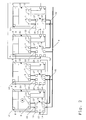
- FIG. 2 shows a further embodiment of the control device arrangement according to the invention.
- four ECUs 20-23 redundantly configured with respect to the ESP (Electronic Stability Program) control function in a vehicle are interconnected in a duo-duplex arrangement.
- the four redundant controllers 20-22 in FIG. 2 are connected via a first data bus 4 to further control devices of the vehicle.
- duo-duplex arrangement requires a second independent data bus for the respective channel.
- the two second data buses 61, 62 serve exclusively to exchange the result signals between in each case two of the four redundantly designed control units 20-23.
- the data buses 4, 61, 62 are designed as CAN (Controller Area Network) data bus.
- the selection means 9 of the control unit 20 in one pair of the duo-duplex arrangement performs comparison operations only with respect to result signals of the another control unit 21.
- the controller 20 provides only an evaluation signal, which is transmitted by means of a signal line from the output port 12 to the input port 13 of the data bus switch 5 of the controller 21 to the data bus switch.
- the data bus circuit breaker 5 of the controller 20 receives via the input port 13, the evaluation signal of the controller 21 with respect to the output data of the controller 20.
- the logic circuit of the data bus switch 5 has as an input signal the evaluation signal on the input port 13.
- the second input signal from the second input port 14 is fixed.
- the value "zero" is defined as the second input signal.
- the data bus circuit breaker 5 of the control unit 20 separates the controller 20 from the communication to the first and second data bus 4, 61 in the event of a fault, as explained above.
- the power supply 8 of the controller 20 is switched off. If a control unit of a control unit pair 20, 21 or 22, 23 fails, the pair 20, 21 or 22, 23 is switched off. This is easy to see since, for example, in the switching off of the first control unit 20 of the pair, the second control unit 21 would not receive an output signal of a redundantly executed control unit via the second data bus 61 and thus would not be able to compare its output signal.
- the control unit 20 is the selected control unit A, which, if there is no error, transmits the result signal to the first data bus 4. If the control unit 20 fails, the pair 20, 21 is switched off. Since the control unit pair 22, 23 monitors via the first data bus 4 whether the control unit 20 sends the output data to the data bus 4, one of the two control units 22, 23 assumes the function of sending the result signal to the data bus 4.
- the logic circuit of the data bus switch 5 is executed in hardware.
- the switchable connection between ports 15, 16 or 17, 18 is designed as a logic module switch.
- the switchable connection can also be designed as a relay switch.
- the bidirectional ports 15-18 may be configured such that, for example, the twisted pair cable of the CAN data bus is looped through or that in each case a corresponding transceiver unit such as a CAN transceiver is attached to the data bus ports 15-18.
- the data buses 4, 60-62 are designed as CAN data buses. However, these could also be embodied as optical data buses such as D2B or MOST or as TTP, LIN, FlexRay, Firewire, etc.
- the control device arrangement according to the invention has a second data bus 60-62 for internal communication between the control devices 1-3, 20-23 configured redundantly for a control function. This is chosen so that the first CAN data bus 4, which ensures the communication with the other control units in the vehicle, is generally already busy in its bandwidth and no additional data traffic, as he used for internal communication between the redundant ECUs 1- 3, 20-23 is needed, more is possible.
- the second data bus 60-62 is no longer necessary.
- the communication between the control units of the vehicle and the communication between the redundant control units 1-3, 20-23 then runs only on the first data bus. 4
- the controller assembly is ideal for asynchronous communication of the controllers.
- the redundantly designed control devices 1-3, 20-23 can come from different manufacturers or be based on different hardware.
- the selection means 9 of the redundant control units 1-3, 20-23 can use different election processes to obtain the evaluation signal.
Abstract
Description
Die Erfindung betrifft Steuergeräteanordnung mit mehreren über einen ersten Datenbus vernetzten Steuergeräten und einen Datenbustrennschalter.The invention relates to a control device arrangement having a plurality of controllers networked via a first data bus and a data bus circuit breaker.
Sicherheitsrelevante Systeme in "Drive-by-Wire"-Fahrzeugen, wobei "Drive-by-Wire" dafür steht, dass jede Antriebsstrangfunktion eines Fahrzeugs, inklusive Lenkung, ausschließlich über elektrische Signale gesteuert wird, müssen gegen Fehlerausfall besonders gesichert sein. Beispiele für "Drive-by-Wire"-Systeme in Fahrzeugen sind "Steer-by-Wire"-Systeme, bei denen keine permanente mechanische bzw. hydraulische Verbindung zwischen dem Lenkrad und der lenkbaren Fahrzeugrädern besteht, oder ESP-(Elektronisches Stabilitäts Programm)-Systeme, bei denen im fahrdynamischen Grenzbereich das Fahrverhalten des Fahrzeugs angepasst wird. Um die Ausfallsicherheit solcher "Drive-by-Wire"-Systeme zu erhöhen, werden diese Systeme redundant ausgelegt, so dass bei Ausfall beispielsweise eines Steuergerätes auf ein redundant ausgelegtes Steuergerät umgeschaltet werden kann.Safety-relevant systems in "drive-by-wire" vehicles, whereby "drive-by-wire" stands for the fact that every powertrain function of a vehicle, including steering, is controlled exclusively by electrical signals must be particularly secured against failure. Examples of "drive-by-wire" systems in vehicles are "steer-by-wire" systems where there is no permanent mechanical or hydraulic connection between the steering wheel and the steerable vehicle wheels, or ESP (Electronic Stability Program) Systems in which the driving behavior of the vehicle is adjusted in the dynamic driving limit range. In order to increase the reliability of such "drive-by-wire" systems, these systems are designed redundantly, so that, for example, a control unit can be switched to a redundant control unit in case of failure.
Ein redundant ausgelegtes System ist ein System in dem ein Bauteil, beispielsweise ein Mikroprozessor, mehrfach vorhanden ist und auf diesen mehrfach vorhandenen Bauteilen dieselbe Funktion ausgeführt wird. Dies bedeutet insbesondere, dass von den Bauteilen dieselben Eingangsdaten verarbeitet und dieselben Ausgangsdaten erzeugt werden, wobei die Ausgangsdaten den Bauteilen zu Auswertungszwecken zugeordnet werden können.A redundantly designed system is a system in which a component, for example a microprocessor, is present multiple times and the same function is performed on these components that are present in multiple places. This means, in particular, that the same input data is processed by the components and the same output data is generated, wherein the output data can be assigned to the components for evaluation purposes.
Bekannte redundante Anordnungen sind das TRM-(Triple Modular Redundancy)-System und das Duo-Duplex-System.Known redundant arrangements are the TRM (Triple Modular Redundancy) system and the duo-duplex system.
Beim TRM-System, auch 2aus3-System genannt, werden drei redundante Bauteile derart gekoppelt, dass ein fehlerhaftes Bauteil erkannt werden kann und seine Auswirkung auf die Umgebung unterbunden wird.In the TRM system, also called a 2-out-of-3 system, three redundant components are coupled in such a way that a faulty component can be detected and its effect on the environment is prevented.
Beim Duo-Duplex-System, auch Dual-Self-Checking-Pair-System genannt, werden jeweils zwei redundante Bauteile zu einem Kanal zusammengefasst, wobei innerhalb eines Kanals das Fehlverhalten eines Bauteils erkannt werden kann. Wird das Fehlverhalten eines Bauteils erkannt wird der korrespondierende Kanal abgeschalten.In the duo-duplex system, also called dual self-checking pair system, two redundant components are combined to form a channel, whereby the malfunction of a component can be detected within a channel. If the malfunction of a component is detected, the corresponding channel is switched off.
Aus der EP 0 760 973 B1 ist ein Verarbeitungssystem in einem Flugzeugdrahtfernlenkungssteuersystem bekannt, worin jeder aus einer Mehrzahl von redundanten, asynchronen primären Flugcomputern Befehlssignale erzeugt, wobei wenigstens eine Steuerfläche des Flugzeugs durch eine Mehrzahl von Stellantrieben gesteuert wird. Das Verarbeitungssystem steuert die Flugbefehlssignale, welche zu den Stellantrieben übermittelt werden, und enthält eine Mehrzahl von Wählern, wobei jeder Wähler mit einem primären Flugcomputer und einem oder mehreren Stellantrieben zum Empfangen der Flugbefehlssignale von allen primären Flugcomputern verbunden ist, und Wählmittel zum Handeln gemäß einem vorbestimmten Wahlalgorithmus aufweist, um ein ausgewähltes Flugsignal zu übermitteln.From EP 0 760 973 B1 a processing system is known in an aircraft wire-line control system wherein each of a plurality of redundant asynchronous primary flight computers generates command signals, wherein at least one control surface of the aircraft is controlled by a plurality of actuators. The processing system controls the flight command signals transmitted to the actuators and includes a plurality of selectors, each selector being connected to a primary flight computer and one or more actuators for receiving the flight command signals from all primary flight computers, and selecting means for acting in accordance with a predetermined one Has election algorithm to transmit a selected flight signal.
In der DE 196 31 309 A1 wird eine Mikroprozessoranordnung für ein Fahrzeugs-Regelungssystem, die mehrere, untereinander durch Bussysteme verbundene, redundant ausgelegte Mikroprozessorsysteme aufweist, offenbart. Die Datenverarbeitung in den Mikroprozessoren dient Regelungssystemen wie Blockierschutz- und/oder Antriebsschlupfregelung sowie der Eingangssignal-Aufbereitung. Die symmetrisch redundanten Ausgangs- und/oder Zwischenergebnisse der Datenverarbeitung werden verglichen. Bei Abweichung wird das betreffende System abgeschalten. Zusätzlich werden die in diesen Mikroprozessorsystemen ablaufenden Datenverarbeitungen jeweils mit den Ergebnissen einer vereinfachten Datenverarbeitung verglichen und auf Plausibilität geprüft. Im Falle von Diskrepanzen kann bei funktionswesentlichen Daten, die nicht "sicherheitskritisch" sind, das Regelungssystem zeitweise aufrechterhalten werden.DE 196 31 309 A1 discloses a microprocessor arrangement for a vehicle control system which has a plurality of redundantly designed microprocessor systems connected to one another by bus systems. The data processing in the microprocessors serves control systems such as anti-lock and / or Traction control and the input signal conditioning. The symmetrically redundant output and / or intermediate results of the data processing are compared. In case of deviation, the relevant system is switched off. In addition, the data processing in these microprocessor systems is compared with the results of a simplified data processing and checked for plausibility. In the case of discrepancies, the control system can be temporarily maintained for functionally important data that are not "safety-critical".
Redundante Systemfunktion eines Verkehrsmittels sind im Allgemeinen über mehrere Mikroprozessoren, welche auf einer Leiterplatine untergebracht, umgesetzt. Diese Umsetzung von redundanten Systemen hat den Vorteil der kurzen und schnellen Schaltwege zwischen den Mikroprozessoren. Der Nachteil ist, dass diese Umsetzung sehr hohe Entwicklungskosten und Entwicklungszeiten mit sich bringt. Dies ist insbesondere im Automobilbereich nachteilig, da dort heute immer kürzere Entwicklungszeiten für für die Generierung neuer Modelle gefordert werden.Redundant system function of a means of transport are generally implemented via a plurality of microprocessors which are accommodated on a printed circuit board. This implementation of redundant systems has the advantage of short and fast switching paths between the microprocessors. The disadvantage is that this implementation brings very high development costs and development times. This is particularly disadvantageous in the automotive sector, since today there are always shorter development times required for the generation of new models.
Aus diesem Grunde sollten redundant ausgelegte Systeme im Automobilbereich aus Bauteilen zusammengesetzt werden, welche bereits auf dem Markt vorhanden sind und nur minimal adaptiert werden müssen, um ein Teil eines redundanten Systems zu sein. Als Bauteile bieten sich insbesondere bereits auf dem Markt befindliche Steuergeräte an.For this reason, redundant systems in the automotive sector should be composed of components that are already on the market and need only be minimally adapted to be part of a redundant system. In particular, already available on the market control units are available as components.
Es ist nun die Aufgabe der vorliegenden Erfindung eine redundante Steuergeräteanordnung derart zu optimieren, dass Steuergeräte minimal als Teil eines redundanten Systems angepasst werden müssen.It is now the object of the present invention to optimize a redundant control device arrangement such that control devices must be minimally adapted as part of a redundant system.
Diese Aufgabe wird erfindungsgemäß durch die Merkmale des Anspruchs 1 und Anspruchs 10 gelöst. Danach ist jeder Datenbustrennschalter mit einer Signalleitung mindestens eines weiteren redundanten Steuergerätes verbunden. Ein weiteres redundantes Steuergerät überträgt ein Bewertungssignal an den einem ersten redundanten Steuergerät zugeordneten Datenbustrennschalter, wobei das Bewertungssignal das Ergebnis einer Funktionsprüfung des weiteren redundanten Steuergerätes bezüglich des ersten redundanten Steuergeräts ist. Der Datenbustrennschalter des ersten redundanten Steuergeräts unterbricht in Abhängigkeit des Ergebnisses einer Logikschaltung den Datenbus, wobei mindestens ein Eingangs-Signal der Logikschaltung von dem mindestens einen Bewertungssignal gebildet wird.This object is achieved by the features of
Die erfindungsgemäße Steuergeräteanordnung hat den Vorteil, dass Steuergeräte beliebiger Hersteller für den Aufbau einer redundanten Anordnung eingesetzt werden können.The control device arrangement according to the invention has the advantage that control devices of any manufacturer can be used for the construction of a redundant arrangement.
Ein weiterer Vorteil ist, dass die Steuergeräteabschaltung bzw. die Trennung vom Datenbus unabhängig von dem auf den redundanten Steuergerät eingesetzten Wahlverfahren ist. Der Wahl- bzw. Voting-Prozess im redundanten Steuergerät zur Bewertung der weiteren redundanten Steuergeräte ist unabhängig von der gewählten Hardware bzw. Sorftware und kann individuell verändert werden. Wichtig ist nur das finale Bewertungssignal, welches an den Datenbustrennschalter des betreffenden bewerteten redundanten Steuergeräts übertragen werden muss.A further advantage is that the control unit shutdown or the separation from the data bus is independent of the dialing method used on the redundant control unit. The voting or voting process in the redundant control unit for evaluating the other redundant control units is independent of the selected hardware or Sorftware and can be changed individually. Important is only the final evaluation signal, which must be transmitted to the data bus circuit breaker of the relevant evaluated redundant control unit.
Der Datenbustrennschalter ist unabhängig vom Steuergerät entwickelbar, da dieser keine funktionalen Anteile vom Steuergerät benötigt, noch das Steuergerät funktionale Anteile vom Datenbustrennschalter benötigt.The data bus circuit breaker can be developed independently of the control unit since it does not require any functional parts from the control unit, nor does the control unit require functional components from the data bus circuit breaker.
Vorteilhaft ist der einfache Aufbau der Steuergeräteanordnung sowie des Datenbustrennschalters, womit eine schnelle und kostengünstige Herstellung gewährleistet ist.The simple construction of the control device arrangement and of the data bus circuit breaker is advantageous, whereby a fast and cost-effective production is ensured.
Da alle Ausgangsbelegungen des Datenbustrennschalters mittels aller Eingangsbelegungen einfach vollständig getestet werden können, ist der Datenbusschalter mit hoher Zuverlässigkeit herstellbar.Since all output assignments of the data bus circuit breaker are simply completely tested by means of all input assignments can, the data bus switch with high reliability can be produced.
Da die Steuergeräteanordnung auf einer kleinsten Einheiten von zwei bezüglich einer Steuerfunktion redundanten Steuergeräten basiert, kann die Steuergeräteanordnung um weitere bezüglich dieser Steuerfunktion redundanten Steuergeräten erweitert werden. Somit lassen sich einfach TRM- und DuoDuplex-Anordnungen abbilden.Since the control device arrangement is based on a smallest unit of two controllers which are redundant with regard to a control function, the controller arrangement can be extended by further controllers redundant with respect to this control function. This makes it easy to map TRM and DuoDuplex devices.
Die Steuergeräteanordnung, welche über einen ersten und zweiten Datenbus aufweist, hat den Vorteil, dass bei Unterbrechung eines Datenbusses diese Unterbrechung über eine Gateway-Schaltung überbrückt werden. Dies kann beispielsweise bei einem Datenbus-Kurzschluss oder einer Datenbus-Kabelunterbrechung eine schnelle Abhilfe sein.The control device arrangement, which has a first and second data bus, has the advantage that when a data bus is interrupted, this interruption is bypassed via a gateway circuit. This can be a quick remedy, for example, for a data bus short or a data bus cable break.
Ein weiterer Vorteil der Steuergeräteanordnung mit dem zweiten zusätzlichen Datenbus ist, dass der erste Datenbus, über den die Kommunikation mit den weiteren Steuergeräten des Verkehrsmittels ausgeführt wird, nicht mit zusätzlichem Datenverkehr belastet wird.A further advantage of the controller arrangement with the second additional data bus is that the first data bus, via which the communication with the further control devices of the means of transport is carried out, is not burdened with additional data traffic.
Es gibt nun verschiedene Möglichkeiten, die Lehre der vorliegenden Erfindung in vorteilhafter Weise auszugestalten und weiterzubilden. Dazu ist einerseits auf die untergeordneten Ansprüche und andererseits auf die nachfolgende Erläuterung einer Ausführungsform zu verweisen. Es sollen auch die vorteilhaften Ausgestaltungen einbezogen sein, die sich aus einer beliebigen Kombination der Unteransprüche ergeben. In der Zeichnung ist eine Ausführungsform der erfindungsgemäßen Steuergeräteanordnung und des erfindungsgemäßen Datenbustrennschalters dargestellt. Es zeigen jeweils in schematischer Darstellung,
- Fig. 1
- ein Blockschaltbild einer ersten Ausführungsform der erfindungsgemäßen Steuergeräteanordnung und
- Fig. 2
- ein Blockschaltbild einer weiteren Ausführungsform der erfindungsgemäßen Steuergeräteanordnung.
- Fig. 1
- a block diagram of a first embodiment of the control device arrangement according to the invention and
- Fig. 2
- a block diagram of another embodiment of the control device arrangement according to the invention.
Die erfindungsgemäße Steuergeräteanordnung ist in Figur 1 abgebildet. Darin sind drei redundant bezüglich der ESP-(Elektronisches Stabilitäts Programm)-Steuerfunktion in einem Fahrzeug ausgelegte Steuergeräte 1, 2, 3 in einer TRM-(Triple Modular Redundancy)-Anordnung zusammengeschalten.The control device arrangement according to the invention is shown in FIG. Therein, three
Die drei redundanten Steuergeräte 1, 2, 3 sind über einen ersten Datenbus 4 mit weiteren Steuergeräten des Fahrzeugs verbunden. Zusätzlich sind die drei redundanten Steuergeräte 1, 2, 3 über einen zweiten Datenbus 60 miteinander verbunden. Dieser Datenbus dient ausschließlich des Austausches der Ergebnissignale zwischen den drei redundant ausgelegten Steuergeräte 1, 2,3. Der erste und zweite Datenbus 4, 60 ist als CAN-(Controller Area Network)-Datenbus ausgeführt.The three
Damit verfügt jedes der drei redundant ausgelegten Steuergeräte 1, 2, 3 über zwei bidirektionale Datenbusanschlüsse 6, 7, wobei der Datenbusanschluss 6 der Verbindung zum ersten Datenbus 4 und der Datenbusanschluss 7 der Verbindung zum zweiten Datenbus 60 dient.Thus, each of the three redundantly designed
Die redundanten Steuergeräte 1, 2, 3 verfügen neben der Recheneinheit mit Prozessor und Speicher zur Durchführung der ESP-Steuerfunktion jeweils über eine Spannungsversorgungseinheit 8 und ein Wahlmittel 9.The
Die Spannungsversorgungseinheit 8 der redundanten Steuergeräte 1, 2, 3 weist einen Eingangsport 10 auf. Über diesen Port 10 kann mittels eines Signals die Spannungsversorgung des Steuergeräts, also das Steuergerät selbst, abgeschalten werden.The
Beispielhaft wird nun an einem Steuergerät 1 die Funktionsweise der erfindungsgemäßen Steuergeräteanordnung in Verbindung mit dem Datenbustrennschalter 5 erläutert. Die weiteren Steuergeräte 2, 3 funktionieren äquivalent.By way of example, the mode of operation of the control device arrangement according to the invention in connection with the
Das Steuergerät 1 verarbeitet Eingangsdaten, welche es über den ersten Datenbus 4 von weiteren an den Datenbus 4 angeschlossenen Steuergeräten, Aktoren, Sensoren usw. erhält. Für die ESP-Steuerfunktion sind diese Eingangsdaten die Gierrate, die Geschwindigkeit, die Motordrehzahl und die Beschleunigung des Fahrzeugs.The
Diese Eingangsdaten werden vom Regelwerk des Steuergeräts 1 verarbeitet und Ausgangsdaten erzeugt. Diese Ausgangsdaten werden auf den zweiten Datenbus 60 gelegt, wo sie von den weiteren Steuergeräten 2, 3 erfasst werden. Das Steuergerät 1 seinerseits erfasst die Ausgangsdaten der weiteren Steuergeräte 2, 3.These input data are processed by the rules of the
Das Wahlmittel 9, auch Voter genannt, dient dazu aus mehreren Vergleichsoperation der eigenen Ausgangsdaten mit den empfangenen Ausgangsdaten der weiteren Steuergeräte 2, 3 eine Bewertung auszuführen. Das Wahlmittel, welches softwaretechnisch umgesetzt ist, ist hierbei so ausgelegt, dass zeitliche und betragsmäßige Abweichungen der Ausgangsdaten erlaubt sind.The selection means 9, also called voter, serves to carry out a comparison of the own output data with the received output data of the
Der Wahlprozess in dem TRM-System geht folgendermaßen vor: Bei Nicht-Übereinstimmung aller drei Ausgangsdaten wird das System abgeschaltet. Bei Übereinstimmung von zwei Ausgangsdaten liegt ein Einfachfehler vor und die übereinstimmenden Ausgangsdaten werden als korrektes Ausgangsdatum übernommen. Bei Übereinstimmung aller drei Ausgangsdaten liegt kein Fehler vor. Jedes Ausgangsdatum kann als Größe übernommen werden.The election process in the TRM system is as follows: If all three output data do not match, the system is shut down. If two output data match, there is a single error and the matching output data are adopted as the correct starting date. If all three output data match, there is no error. Each starting date can be adopted as a size.
Nach Abschluss des Wahlprozesses ordnet das Wahlmittel 9 den gesendeten Ausgangssignalen der weiteren Steuergeräte 2, 3 jeweils ein Bewertungssignal zu.After completion of the election process, the voting means 9 assigns to the transmitted output signals of the
Nur ein ausgezeichnetes A der drei redundanten Steuergeräte 1, 2, 3, hier das Steuergerät 1, ist das Steuergerät, welches sein Ausgangssignal nach dem Wahlprozess auf den ersten Datenbus 4 zur Befehlsübermittlung an die weiteren an den Datenbus 4 angeschlossenen Steuergeräte sendet. Wurde nach einem Wahlprozess festgestellt, dass das Steuergerät 1 fehlerhaft arbeitet, übernimmt eines der weiteren Steuergeräte 2, 3 die Aufgabe das nach dem Wahlprozess ermittelte Ausgangsdatum auf den ersten Datenbus 4 zu senden. Hierzu ist im Wahlmittel ein Parameter hinterlegt, der angibt, welches Steuergerät der redundant ausgelegten Steuergeräte 1-3 diese Funktion übernimmt.Only an excellent A of the three
Das Steuergerät 1 in Figur 1 weist zwei Ausgangsports 11, 12 auf, die zur Übermittlung der Bewertungssignale der Ausgangsdaten der weiteren redundanten Steuergeräte 2, 3 dienen. Diese Ausgangsports 11, 12 sind über eine jeweilige Signalleitung mit den Eingangsports 13, 14 der jeweiligen Datenbustrennschalter 5 der weiteren Steuergeräte 2, 3 verbunden. Über diese Signalleitung wird das Bewertungssignal an die jeweiligen Datenbustrennschalter der Steuergeräte 2, 3 übermittelt.The
Der Datenbustrennschalter 5 weist jeweils zwei über Schalter verbundene bidirektionale Datenbusanschlüsse 15, 16 bzw. 17, 18 auf. Die Datenbusanschlüsse 15-18 sind derart geschalten, dass diese die Verbindung des Steuergeräts 1 zum ersten Datenbus 4 über die Anschlüsse 15, 16 und zum zweiten Datenbus 60 über die Anschlüsse 17, 18 herstellt oder trennt.The data
Der Datenbustrennschalter 5 weist zusätzlich eine LogikSchaltung auf, deren Eingangssignale von den Eingangports 13, 14 des Datenbustrennschalters 5 gebildet werden. An den Eingangsports 13, 14 des Datenbustrennschalters 5 werden die Bewertungssignale der weiteren Steuergeräte 2, 3 über die Ausgangssignale des Steuergeräts 1 übermittelt.The
Die Logikschaltung des Datenbustrennschalters 5 besteht aus einem ODER-Gatter. Die an den Eingangports 13, 14 ankommenden Bewertungssignale haben entweder den Wert Null für Nicht-Übereinstimmung oder den Wert Eins für Übereinstimmung der Ausgangssignale. In Abhängigkeit des Ergebnisses der LogikSchaltung, also Null für fehlerhaftes Steuergerät 1 oder Eins für fehlerfreies Steuergerät 1, trennt der Datenbustrennschalter im Fehlerfall die Verbindung zwischen den Datenbusanschlüssen 15, 16 bzw. 17, 18. Damit ist das Steuergerät 1 im Fehlerfall von der Kommunikation über den ersten und zweiten Datenbus 4, 60 abgetrennt.The logic circuit of the
Zusätzlich weist der Datenbustrennschalter einen Ausgangsport 19 auf. Dieser Ausgangsport 19 des Steuergeräts 1 ist über eine Signalleitung mit dem Eingangsport 10 der Spannungsversorgung des Steuergeräts 1 verbunden. Im Fehlerfall sendet der Datenbustrennschalter 5 zusätzlich ein Signal über den Ausgangsport 19 des Datenbustrennschalters 5 an den Eingangsport 10 der Spannungsversorgung 8, welches die Spannungsversorgung 8 des Steuergeräts 1 und damit das Steuergerät 1 selbst abschaltet.In addition, the data bus switch has an
In Figur 2 ist eine weiter Ausführungsform der erfindungsgemäßen Steuergeräteanordnung abgebildet. Darin sind vier redundant bezüglich der ESP-(Elektronisches Stabilitäts Programm)-Steuerfunktion in einem Fahrzeug ausgelegten Steuergeräte 20-23 in einer Duo-Duplex-Anordnung zusammengeschalten. Die vier redundanten Steuergeräte 20-22 in Figur 2 sind über einen ersten Datenbus 4 mit weiteren Steuergeräten des Fahrzeugs verbunden.FIG. 2 shows a further embodiment of the control device arrangement according to the invention. Therein, four ECUs 20-23 redundantly configured with respect to the ESP (Electronic Stability Program) control function in a vehicle are interconnected in a duo-duplex arrangement. The four redundant controllers 20-22 in FIG. 2 are connected via a
Wie eingangs ausgeführt, werden bei einer Duo-Duplex-Anordnung jeweils zwei redundante Steuergeräte der vier bezüglich der ESP-Steuerfunktion redundant ausgelegten Steuergeräte zu einem logischen Kanal zusammengefasst. Also benötigt die Duo-Duplex-Anordnung im Gegensatz zur TRM-Anordnung einen zweiten unabhängigen Datenbus für den jeweiligen Kanal.As stated above, two redundant control units of the four with respect to the ESP control function redundantly designed control units are combined to form a logical channel in a duo-duplex arrangement. So in contrast to the TRM arrangement, the duo-duplex arrangement requires a second independent data bus for the respective channel.
Damit sind jeweils zwei, 20,21 bzw. 22,23 der vier redundanten Steuergeräte 20-23 in Figur 2 über einen zweiten Datenbus 61 bzw. 62 miteinander verbunden. Die beiden zweiten Datenbusse 61, 62 dienen ausschließlich dem Austausch der Ergebnissignale zwischen jeweils zwei der vier redundant ausgelegten Steuergeräte 20-23. Der Datenbusse 4, 61, 62 sind als CAN-(Controller Area Network)-Datenbus ausgeführt.Thus, in each case two, 20, 21 or 22, 23 of the four redundant control devices 20-23 in FIG. 2 are connected to one another via a
Beispielhaft wird nun an dem Steuergerätepaar 20, 21 die Funktionsweise der erfindungsgemäßen Steuergeräteanordnung in der Duo-Duplex-Anordnung erläutert. Das weitere Steuergerätepaar 22, 23 funktioniert äquivalent. Auf Funktionsweisen der einzelnen Komponenten soweit dies bereits in der Figur 1 erläutert wurde, wird nicht mehr eingegangen.By way of example, the mode of operation of the control unit arrangement according to the invention in the duo-duplex arrangement will now be explained on the
Das Wahlmittel 9 des Steuergeräts 20 in einem Paar der Duo-Duplex-Anordnung führt Vergleichsoperationen nur bezüglich Ergebnissignalen des einen weiteren Steuergeräts 21 aus. Damit liefert das Steuergerät 20 nur ein Bewertungssignal, welches mittels einer Signalleitung vom den Ausgangsport 12 an den Eingangsport 13 des Datenbustrennschalters 5 des Steuergeräts 21 an den Datenbustrennschalter übermittelt wird.The selection means 9 of the
Der Datenbustrennschalter 5 des Steuergeräts 20 erhält über den Eingangsport 13 das Bewertungssignal des Steuergeräts 21 bezüglich der Ausgangsdaten des Steuergeräts 20. Die Logikschaltung des Datenbustrennschalters 5 hat als ein Eingangssignal das Bewertungssignal auf dem Eingangsport 13. Das zweite Eingangssignal vom zweiten Eingangsport 14 wird fest vorgegeben. Hier wird als zweites Eingangssignal der Wert "Null" festgelegt.The data
Der Datenbustrennschalter 5 des Steuergeräts 20 trennt wie oben ausgeführt im Fehlerfall das Steuergerät 20 von der Kommunikation zum ersten und zweiten Datenbus 4, 61. Zudem wird die Spannungsversorgung 8 des Steuergeräts 20 abgeschalten. Fällt ein Steuergerät eines Steuergerätepaares 20, 21 bzw. 22, 23 aus, so wird das Paar 20, 21 bzw. 22, 23 abgeschalten. Dies ist leicht einzusehen, da beispielsweise in dem Abschalten des ersten Steuergeräts 20 des Paares das zweite Steuergerät 21 kein Ausgangssignal eines redundant ausgeführten Steuergeräts über den zweiten Datenbus 61 erhalten würde und damit nicht in der Lage wäre sein Ausgangssignal zu vergleichen.The data
Das Steuergerät 20 ist das ausgewählte Steuergerät A, welches sofern kein Fehler vorliegt das Ergebnissignal auf den ersten Datenbus 4 überträgt. Fällt das Steuergerät 20 aus wird das Paar 20, 21 abgeschaltet. Da das Steuergerätepaar 22, 23 über den ersten Datenbus 4 überwacht, ob das Steuergerät 20 die Ausgangsdaten auf den Datenbus 4 sendet, übernimmt eines der beiden Steuergeräte 22, 23 die Funktion des Sendens des Ergebnissignals auf den Datenbus 4.The
Die Logikschaltung des Datenbustrennschalters 5 ist hardwaremäßig ausgeführt. Die schaltbare Verbindung zwischen den Ports 15, 16 bzw. 17, 18 ist als Logikbausteinschalter ausgeführt. Die schaltbare Verbindung kann aber auch als Relaisschalter ausgeführt sein.The logic circuit of the
Die bidirektionalen Anschlüsse 15-18 können derart gestaltet sein, dass beispielsweise das Twisted-Pair-Kabel des CAN-Datenbusses durchgeschleift ist oder dass jeweils eine entsprechende Sende-/Empfangseinheit wie beispielsweise ein CAN-Transceiver an den Datenbusanschlussstellen 15-18 angebracht ist.The bidirectional ports 15-18 may be configured such that, for example, the twisted pair cable of the CAN data bus is looped through or that in each case a corresponding transceiver unit such as a CAN transceiver is attached to the data bus ports 15-18.
Die Datenbusse 4, 60-62 sind als CAN-Datenbusse ausgelegt. Diese könnten aber auch als optische Datenbusse wie D2B bzw. MOST oder als TTP, LIN, FlexRay, Firewire usw. ausgeführt sein.The
Die erfindungsgemäße Steuergeräteanordnung weist einen zweiten Datenbus 60-62 zu internen Kommunikation zwischen den für eine Steuerfunktion redundant ausgelegten Steuergeräten 1-3, 20-23 auf. Dies ist so gewählt, da der erste CAN-Datenbus 4, welcher die Kommunikation mit den weiteren Steuergeräten im Fahrzeug gewährleistet, im Allgemeinen in seiner Bandbreite bereits ausgelastet ist und keine zusätzlicher Datenverkehr, wie er für die interne Kommunikation zwischen den redundant ausgelegten Steuergeräte 1-3, 20-23 benötigt wird, mehr möglich ist.The control device arrangement according to the invention has a second data bus 60-62 for internal communication between the control devices 1-3, 20-23 configured redundantly for a control function. This is chosen so that the first
Erlaubt das gewählte Datenbussytem eine entsprechend große Bandbreite, so dass die zusätzliche Kommunikation zwischen den redundant ausgelegten Steuergeräten 1-3, 20-23 mit der entsprechenden Geschwindigkeit gewährleist ist, ist der zweite Datenbus 60-62 nicht mehr nötig. Die Kommunikation zwischen den Steuergeräten des Fahrzeugs sowie die Kommunikation zwischen den redundant ausgelegten Steuergeräten 1-3, 20-23 läuft dann nur über den ersten Datenbus 4.If the selected data bus system permits a correspondingly large bandwidth, so that the additional communication between the redundantly designed control devices 1-3, 20-23 is ensured at the corresponding speed, the second data bus 60-62 is no longer necessary. The communication between the control units of the vehicle and the communication between the redundant control units 1-3, 20-23 then runs only on the first data bus. 4
Die Steuergeräteanordnung ist ideal bei asynchroner Kommunikation der Steuergeräte. Arbeiten die Steuergeräte synchron, also senden diese nur zu einer bestimmten Zeit, wobei die Zeit über eine Gesamtsystemzeit genormt ist, hat dies den Nachteil, dass ein Ausfall des Synchronisationsmechanismusses sich auf alle Steuergeräte der redundanten Anordnung auswirkt und die gesamte redundante Anordnung damit ausfällt.The controller assembly is ideal for asynchronous communication of the controllers. Working the control units synchronous, so send them only at a certain time, with the time is standardized over a total system time, this has the disadvantage that a failure of the synchronization mechanism affects all controllers of the redundant arrangement and the entire redundant arrangement fails.
Die redundant ausgelegten Steuergeräte 1-3, 20-23 können von unterschiedlichen Herstellern stammen bzw. auf unterschiedlicher Hardware aufgebaut sein.The redundantly designed control devices 1-3, 20-23 can come from different manufacturers or be based on different hardware.
Das Wahlmittel 9 der redundanten Steuergeräte 1-3, 20-23 kann unterschiedliche Wahlprozesse einsetzen, um das Bewertungssignal zu erhalten.The selection means 9 of the redundant control units 1-3, 20-23 can use different election processes to obtain the evaluation signal.
Claims (11)
- Array of control devices having a plurality of control devices (1 - 3, 20 - 23) which are interconnected via a first data bus (4) and which- control components of a means of transportation, and- exchange information with one another via the first data bus (4),- control devices (1 - 3; 20 - 23) which are of redundant configuration with respect to a control function being provided, and- in each case a data bus isolating switch (5) being assigned to the control devices (1 - 3; 20 - 23) which are of redundant configuration, said data bus isolating switch (5) connecting or disconnecting the data bus (4) as a function of an evaluation signal, with the result that the data bus communication is activated or deactivated,characterized in that- each of these data bus isolating switches (5) is connected to a signal line of at least one further redundant control device (1 - 3; 20 - 23), in that- a further redundant control device (2, 3; 21; 23) transmits an evaluation signal to the data bus isolating switch (5) which is assigned to a first redundant control device (1; 20; 22), the evaluation signal being the result of functional checking of the further redundant control device (2, 3; 21; 23) with respect to the first redundant control device (1; 20; 22), and- the data bus isolating switch (5) of the first redundant control device (1; 20; 22) disconnecting the data bus (4) as a function of the result of a logic circuit, at least one input signal of the logic circuit being formed by the at least one evaluation signal.
- Array of control devices according to Claim 1, characterized in that the control devices (1 - 3; 20 - 23) which are of redundant configuration with respect to a control function are connected via a second data bus (60 - 62) in order to exchange the result signals of the control function.
- Array of control devices according to Claim 1 or 2, characterized in that the result signal of the control function is transmitted to the first data bus (4) via a predefinable control device (A) from the control devices (1 - 3; 20 - 23) which are of redundant configuration with respect to a control function.
- Array of control devices according to Claim 3, characterized in that one predefinable control device (A) can be defined via a parameter in the control devices (1 - 3; 20 - 23) which are of redundant configuration with respect to a control function.
- Array of control devices according to Claim 4, characterized in that the parameter maps the sequence of the replacement for one control device (A) from the control devices (1 - 3 20 - 23) which form a replacement for control devices which are of redundant configuration with respect to a control function.
- Array of control devices according to Claims 2 to 5, characterized in that the control devices (1 - 3; 20 - 23) which are of redundant configuration with respect to a control function have a gateway function, with the result that when a data bus (4; 60 - 62) is disconnected, the exchange of data is maintained via the further data bus (60 - 62; 4) by means of the gateway functionality.
- Array of control devices according to Claims 1 to 6, characterized in that- the data bus isolating switch (5) has at least one input port (13, 14) for the evaluation signal of at least one further control device (2, 3; 21; 23), and- the connection for the data bus (4) can be switched in a controlled fashion via a logic circuit,- at least one evaluation signal forming an input signal of the logic circuit in order to disconnect- the communication of the assigned control device (1; 20; 22) to the first data bus (4)as a function of the result of the logic circuit.
- Array of control devices according to Claim 7,
characterized in that- the data bus isolating switch (5) has an output port (19) which is connected to the voltage supply (8) of the assigned control device (1; 20; 22) via a signal line, and- in that a control signal is transmitted via the signal line as a function of the result of the logic circuit and disconnects the assigned control device (1; 20; 22) from the voltage supply (8). - Array of control devices according to Claim 7 or 8, characterized in that the switchable connection is embodied as- a relay switch or- as a logic module.
- Data bus isolating switch (5) having a switchable electrical connection for a data bus (4, 60 - 62),- the data bus (4, 60 - 62) being connected to a data bus connection (15, 17) of the data bus isolating switch (5) by a transceiver unit of a control device (1 - 3, 20 - 22) which is assigned to the transceiver unit, characterized in that- the data bus isolating switch (5) has at least one input port (13, 14) for the evaluation signal of at least one further control device (2, 3; 21; 23),- has an output port (19) which is connected to the voltage supply (8) of the assigned control device (1; 20; 22) via a signal line, and- the connection can be switched via a logic circuit,- at least one evaluation signal forming an input signal of the logic circuit in order- to disconnect the communication of the control device (1; 20; 22) with the data bus (4, 60 - 62) and- to transmit, via the signal line, a control signal which disconnects the control device (1; 20; 22) from the voltage supply (8),as a function of the result of the logic circuit.
- Data bus isolating switch according to Claim 10,
characterized in that the switchable connection is embodied as- a relay switch or- as a logic module.
Applications Claiming Priority (3)
| Application Number | Priority Date | Filing Date | Title |
|---|---|---|---|
| DE10243713A DE10243713B4 (en) | 2002-09-20 | 2002-09-20 | Redundant control unit arrangement |
| DE10243713 | 2002-09-20 | ||
| PCT/EP2003/009642 WO2004029737A1 (en) | 2002-09-20 | 2003-08-30 | Redundant control unit arrangement |
Publications (2)
| Publication Number | Publication Date |
|---|---|
| EP1540428A1 EP1540428A1 (en) | 2005-06-15 |
| EP1540428B1 true EP1540428B1 (en) | 2006-10-04 |
Family
ID=31969318
Family Applications (1)
| Application Number | Title | Priority Date | Filing Date |
|---|---|---|---|
| EP03747947A Expired - Lifetime EP1540428B1 (en) | 2002-09-20 | 2003-08-30 | Redundant control unit arrangement |
Country Status (5)
| Country | Link |
|---|---|
| US (1) | US7483778B2 (en) |
| EP (1) | EP1540428B1 (en) |
| JP (1) | JP3965410B2 (en) |
| DE (2) | DE10243713B4 (en) |
| WO (1) | WO2004029737A1 (en) |
Families Citing this family (41)
| Publication number | Priority date | Publication date | Assignee | Title |
|---|---|---|---|---|
| DE10259546A1 (en) * | 2002-12-19 | 2004-07-01 | Robert Bosch Gmbh | Device for wireless transmission of a trigger signal |
| EP1758778B1 (en) * | 2004-05-13 | 2012-02-29 | Haldex Brake Products Aktiebolag | Control and power supply network for vehicle braking system |
| JP5013668B2 (en) | 2004-11-19 | 2012-08-29 | 株式会社デンソー | Vehicle control system |
| DE102005034161B3 (en) | 2005-07-21 | 2006-10-12 | Siemens Ag | Electronic device e.g. turning rate sensor for use in motor vehicles has uncoupling elements for decoupling grids based on noise influence |
| ES2436609T3 (en) | 2006-05-16 | 2014-01-03 | Saab Ab | Fault tolerance data bus node in a distributed system |
| KR100871857B1 (en) * | 2007-06-11 | 2008-12-03 | 성균관대학교산학협력단 | Network system of in-vehicle and control method thereof |
| DE102007033885A1 (en) * | 2007-07-20 | 2009-01-22 | Siemens Ag | Method for the transparent replication of a software component of a software system |
| DE102007046706A1 (en) * | 2007-09-28 | 2009-04-16 | Autoliv Development Ab | Control device for vehicles |
| US7941253B1 (en) * | 2007-11-27 | 2011-05-10 | Brunswick Corporation | Marine propulsion drive-by-wire control system with shared isolated bus |
| US8213706B2 (en) * | 2008-04-22 | 2012-07-03 | Honeywell International Inc. | Method and system for real-time visual odometry |
| US8130773B2 (en) * | 2008-06-25 | 2012-03-06 | Honeywell International Inc. | Hybrid topology ethernet architecture |
| FR2934693B1 (en) * | 2008-07-30 | 2011-03-25 | Airbus France | A DYNAMIC RECONFIGURATION ONBOARD AERONAUTICAL SYSTEM, ASSOCIATED METHOD AND AIRCRAFT EMBARKING SUCH A SYSTEM. |
| US8441766B2 (en) * | 2008-11-18 | 2013-05-14 | Rockwell Automation Technologies, Inc. | Apparatus for fault tolerant digital outputs |
| US8149554B2 (en) * | 2008-11-18 | 2012-04-03 | Rockwell Automation Technologies, Inc. | Apparatus for fault tolerant digital inputs |
| DE102008060984A1 (en) * | 2008-12-06 | 2010-06-10 | Dr. Ing. H.C. F. Porsche Aktiengesellschaft | Method for protection against external intervention in a master / slave bus system and master / slave bus system |
| DE102009005266A1 (en) | 2009-01-20 | 2010-07-22 | Continental Teves Ag & Co. Ohg | Method for operating communication node of flex ray communication system of e.g. car, involves determining whether reestablishment of communication between controller and process computer is allowed when error occurs in computer |
| FR2943037B1 (en) * | 2009-03-11 | 2012-09-21 | Airbus France | AIRCRAFT CONTROL SYSTEM WITH INTEGRATED MODULAR ARCHITECTURE. |
| US8156371B2 (en) * | 2009-06-16 | 2012-04-10 | Honeywell International Inc. | Clock and reset synchronization of high-integrity lockstep self-checking pairs |
| DE102011082969B4 (en) | 2011-09-19 | 2015-04-30 | Siemens Aktiengesellschaft | Method for operating a communication network and network arrangement |
| JP6227239B2 (en) * | 2011-11-16 | 2017-11-08 | ナブテスコ株式会社 | Aircraft control apparatus and aircraft control system |
| DE102012209108B4 (en) * | 2012-05-30 | 2014-05-15 | Siemens Aktiengesellschaft | Network device, network device and method for operating a network device |
| DE102012106652A1 (en) * | 2012-07-23 | 2014-01-23 | Endress + Hauser Gmbh + Co. Kg | Field device for determining or monitoring a process variable in automation technology |
| US9266518B2 (en) * | 2013-11-08 | 2016-02-23 | GM Global Technology Operations LLC | Component control system for a vehicle |
| KR101704787B1 (en) * | 2014-12-31 | 2017-02-22 | 주식회사 효성 | Dual apparatus for controller |
| DE102015201278B4 (en) * | 2015-01-26 | 2016-09-29 | Continental Automotive Gmbh | control system |
| WO2016155763A1 (en) * | 2015-03-30 | 2016-10-06 | Volvo Truck Corporation | Method and arrangement for providing redundancy in a vehicle electrical control system |
| JP6777641B2 (en) | 2015-09-29 | 2020-10-28 | 日立オートモティブシステムズ株式会社 | Surveillance system and vehicle control device |
| DE102015218898A1 (en) * | 2015-09-30 | 2017-03-30 | Robert Bosch Gmbh | Method for the redundant processing of data |
| DE102016015616B4 (en) * | 2016-12-28 | 2021-12-30 | Bachmann Gmbh | Module system with bus connection and direct wire connection |
| CN110325423B (en) | 2017-02-23 | 2023-05-02 | 本田技研工业株式会社 | Control system and control method for vehicle |
| CN110300691B (en) * | 2017-02-23 | 2022-08-09 | 本田技研工业株式会社 | Vehicle control system |
| CN110290999B (en) | 2017-02-23 | 2022-10-14 | 本田技研工业株式会社 | Vehicle control system and control method |
| US10394241B2 (en) * | 2017-06-15 | 2019-08-27 | GM Global Technology Operations LLC | Multi-stage voting control |
| US10647329B2 (en) | 2017-12-12 | 2020-05-12 | Uatc, Llc | Disengaging autonomous control of vehicle |
| KR102482143B1 (en) * | 2018-01-30 | 2022-12-29 | 에이치엘만도 주식회사 | Electronic control unit and electronic control unit driving method |
| KR102111295B1 (en) * | 2018-02-05 | 2020-05-15 | 주식회사 만도 | Apparatus and method for controlling vehicle based on redundant architecture |
| EP3761568B1 (en) * | 2019-07-01 | 2023-05-31 | Volvo Car Corporation | Method of controlling communication over a local interconnect network bus |
| CN112735310B (en) * | 2020-12-22 | 2022-08-02 | 北京市轨道交通运营管理有限公司 | Testing system and high-precision testing method for ceiling guide display panel |
| DE102021112121A1 (en) | 2021-05-10 | 2022-11-10 | Schaeffler Technologies AG & Co. KG | Method for data transmission within a vehicle control system, control system and motor vehicle |
| EP4116620A1 (en) * | 2021-07-09 | 2023-01-11 | Leuze electronic GmbH + Co. KG | Monitoring device and method for operating same |
| EP4187858A1 (en) | 2021-11-29 | 2023-05-31 | KNORR-BREMSE Systeme für Nutzfahrzeuge GmbH | A secondary control unit for a vehicle with a primary control unit and a data transmission path |
Family Cites Families (16)
| Publication number | Priority date | Publication date | Assignee | Title |
|---|---|---|---|---|
| US4621327A (en) * | 1984-06-13 | 1986-11-04 | Nartron Corporation | Electronic power steering method and apparatus |
| US4622667A (en) * | 1984-11-27 | 1986-11-11 | Sperry Corporation | Digital fail operational automatic flight control system utilizing redundant dissimilar data processing |
| DE3638947C2 (en) * | 1986-11-14 | 1995-08-31 | Bosch Gmbh Robert | Process for the synchronization of computers of a multi-computer system and multi-computer system |
| DE4122016A1 (en) * | 1991-07-03 | 1993-01-21 | Hella Kg Hueck & Co | ANTI-BLOCKING CONTROL SYSTEM |
| US5493497A (en) | 1992-06-03 | 1996-02-20 | The Boeing Company | Multiaxis redundant fly-by-wire primary flight control system |
| JPH07507892A (en) | 1992-06-12 | 1995-08-31 | ザ、ダウ、ケミカル、カンパニー | Transparent interface for process control computers |
| JPH06348524A (en) | 1993-06-10 | 1994-12-22 | Hitachi Ltd | Multiplexing controller |
| US5515282A (en) * | 1994-04-25 | 1996-05-07 | The Boeing Company | Method and apparatus for implementing a databus voter to select flight command signals from one of several redundant asynchronous digital primary flight computers |
| DE4439060A1 (en) | 1994-11-02 | 1996-05-09 | Teves Gmbh Alfred | Microprocessor arrangement for a vehicle control system |
| DE19612423A1 (en) | 1996-03-28 | 1997-10-02 | Siemens Ag | Redundant control and safety system for crane |
| DE19631309A1 (en) * | 1996-08-02 | 1998-02-05 | Teves Gmbh Alfred | Microprocessor arrangement for a vehicle control system |
| DE19915253A1 (en) | 1999-04-03 | 2000-10-05 | Bosch Gmbh Robert | Operator for car divided control system in motor vehicle, has several electronic units mutually exchanging data via communications system |
| DE19944939C1 (en) * | 1999-09-20 | 2001-08-30 | Mannesmann Vdo Ag | Control device for a motor vehicle |
| DE19947251A1 (en) | 1999-09-30 | 2001-05-31 | Bosch Gmbh Robert | Process and device for controlling processes in connection with a drive |
| DE10002519C1 (en) | 2000-01-21 | 2001-04-05 | Siemens Ag | Error prevention method for signal processing system e.g. in automobile |
| DE10162689A1 (en) | 2001-01-12 | 2002-07-18 | Daimler Chrysler Ag | Method for monitoring sensors within a motor vehicle to ensure their correct operation using a system with a high degree of built-in redundancy to ensure that one device at each stage of a measurement chain is always working |
-
2002
- 2002-09-20 DE DE10243713A patent/DE10243713B4/en not_active Expired - Fee Related
-
2003
- 2003-08-30 JP JP2004538854A patent/JP3965410B2/en not_active Expired - Fee Related
- 2003-08-30 US US10/513,826 patent/US7483778B2/en not_active Expired - Fee Related
- 2003-08-30 DE DE50305291T patent/DE50305291D1/en not_active Expired - Lifetime
- 2003-08-30 EP EP03747947A patent/EP1540428B1/en not_active Expired - Lifetime
- 2003-08-30 WO PCT/EP2003/009642 patent/WO2004029737A1/en active IP Right Grant
Also Published As
| Publication number | Publication date |
|---|---|
| DE10243713A1 (en) | 2004-04-01 |
| WO2004029737A1 (en) | 2004-04-08 |
| JP2005521182A (en) | 2005-07-14 |
| DE10243713B4 (en) | 2006-10-05 |
| DE50305291D1 (en) | 2006-11-16 |
| US20060116803A1 (en) | 2006-06-01 |
| US7483778B2 (en) | 2009-01-27 |
| EP1540428A1 (en) | 2005-06-15 |
| JP3965410B2 (en) | 2007-08-29 |
Similar Documents
| Publication | Publication Date | Title |
|---|---|---|
| EP1540428B1 (en) | Redundant control unit arrangement | |
| EP1763454B1 (en) | Redundant data bus system | |
| EP1456720B1 (en) | Multi-core redundant control computer system, computer network for applications that are critical with regard to safety in motor vehicles, and use thereof | |
| EP0092719B1 (en) | Arrangement for the coupling of digital processing units | |
| EP3661819B1 (en) | Control system for a motor vehicle, motor vehicle, method for controlling a motor vehicle, computer program product, and computer-readable medium | |
| DE4416795C2 (en) | Redundantly configurable transmission system for data exchange and method for its operation | |
| DE102017204691B3 (en) | Control device for redundantly performing an operating function and motor vehicle | |
| DE102017218395A1 (en) | Method for fault-tolerant control of highly automated vehicles | |
| DE102008009652A1 (en) | Monitoring device and monitoring method for a sensor, and sensor | |
| EP2297619B1 (en) | Monitoring system | |
| EP2862093B1 (en) | Sensor arrangement for an electric/electronic architecture and associated electric/electronic architecture for a vehicle | |
| DE4416879B4 (en) | Control device with means for switching between two data lines | |
| EP1410577A1 (en) | Network component for an optical network comprising an emergency operation function, especially for an optical network in ring topology | |
| DE60319175T2 (en) | Data transmission system in the vehicle with redundant connections | |
| DE102011115318B4 (en) | Flight control system | |
| DE102018220605A1 (en) | Motor vehicle network and method for operating a motor vehicle network | |
| DE102010038459A1 (en) | Safety system, has safety module comprising system interface for direct contacting and communication with group protection unit, and load branch comprising another system interface for direct communication with safety module | |
| DE102016203966A1 (en) | Control unit and method for controlling at least one actuator of a vehicle | |
| DE19944132A1 (en) | System for the process-controlled transmission of electrical signals and electrical energy within a military vehicle | |
| EP3281365B1 (en) | Interface extension device for a network device and method for operating an interface extension device | |
| EP3567809A2 (en) | System for controlling, regulating and/or monitoring an aircraft | |
| DE102018203887B4 (en) | Control device for a multi-voltage vehicle electrical system and multi-voltage vehicle electrical system | |
| DE102005001421A1 (en) | Data bus disconnection circuit for e.g. triple modular redundancy system in vehicle, has signal paths each having two separation units, for examining proper functioning of circuit during separation and connection modes | |
| EP1675310B1 (en) | Method for datacommunication and data bus system for automobile | |
| DE102020112955B4 (en) | Modular device, automation system and process automation process |
Legal Events
| Date | Code | Title | Description |
|---|---|---|---|
| PUAI | Public reference made under article 153(3) epc to a published international application that has entered the european phase |
Free format text: ORIGINAL CODE: 0009012 |
|
| 17P | Request for examination filed |
Effective date: 20040331 |
|
| AK | Designated contracting states |
Kind code of ref document: A1 Designated state(s): AT BE BG CH CY CZ DE DK EE ES FI FR GB GR HU IE IT LI LU MC NL PT RO SE SI SK TR |
|
| RBV | Designated contracting states (corrected) |
Designated state(s): AT BE BG CH DE FR GB IT LI |
|
| GRAP | Despatch of communication of intention to grant a patent |
Free format text: ORIGINAL CODE: EPIDOSNIGR1 |
|
| RBV | Designated contracting states (corrected) |
Designated state(s): DE FR GB IT |
|
| RIN1 | Information on inventor provided before grant (corrected) |
Inventor name: ARMBRUSTER, MICHAEL Inventor name: SPIEGELBERG, GERNOT Inventor name: SULZMANN, ARMIN Inventor name: HEILMANN, HARRO Inventor name: SCHWARZHAUPT, ANDREAS Inventor name: ROOKS, OLIVER Inventor name: MAISCH, ANSGAR |
|
| GRAS | Grant fee paid |
Free format text: ORIGINAL CODE: EPIDOSNIGR3 |
|
| GRAA | (expected) grant |
Free format text: ORIGINAL CODE: 0009210 |
|
| AK | Designated contracting states |
Kind code of ref document: B1 Designated state(s): DE FR GB IT |
|
| PG25 | Lapsed in a contracting state [announced via postgrant information from national office to epo] |
Ref country code: IT Free format text: LAPSE BECAUSE OF FAILURE TO SUBMIT A TRANSLATION OF THE DESCRIPTION OR TO PAY THE FEE WITHIN THE PRESCRIBED TIME-LIMIT;WARNING: LAPSES OF ITALIAN PATENTS WITH EFFECTIVE DATE BEFORE 2007 MAY HAVE OCCURRED AT ANY TIME BEFORE 2007. THE CORRECT EFFECTIVE DATE MAY BE DIFFERENT FROM THE ONE RECORDED. Effective date: 20061004 |
|
| REG | Reference to a national code |
Ref country code: GB Ref legal event code: FG4D Free format text: NOT ENGLISH |
|
| GBT | Gb: translation of ep patent filed (gb section 77(6)(a)/1977) |
Effective date: 20061016 |
|
| REF | Corresponds to: |
Ref document number: 50305291 Country of ref document: DE Date of ref document: 20061116 Kind code of ref document: P |
|
| RAP2 | Party data changed (patent owner data changed or rights of a patent transferred) |
Owner name: DAIMLERCHRYSLER AG |
|
| EN | Fr: translation not filed | ||
| PLBE | No opposition filed within time limit |
Free format text: ORIGINAL CODE: 0009261 |
|
| STAA | Information on the status of an ep patent application or granted ep patent |
Free format text: STATUS: NO OPPOSITION FILED WITHIN TIME LIMIT |
|
| 26N | No opposition filed |
Effective date: 20070705 |
|
| PG25 | Lapsed in a contracting state [announced via postgrant information from national office to epo] |
Ref country code: FR Free format text: LAPSE BECAUSE OF FAILURE TO SUBMIT A TRANSLATION OF THE DESCRIPTION OR TO PAY THE FEE WITHIN THE PRESCRIBED TIME-LIMIT Effective date: 20070525 |
|
| PG25 | Lapsed in a contracting state [announced via postgrant information from national office to epo] |
Ref country code: FR Free format text: LAPSE BECAUSE OF FAILURE TO SUBMIT A TRANSLATION OF THE DESCRIPTION OR TO PAY THE FEE WITHIN THE PRESCRIBED TIME-LIMIT Effective date: 20061004 |
|
| PGFP | Annual fee paid to national office [announced via postgrant information from national office to epo] |
Ref country code: GB Payment date: 20100819 Year of fee payment: 8 |
|
| GBPC | Gb: european patent ceased through non-payment of renewal fee |
Effective date: 20110830 |
|
| PG25 | Lapsed in a contracting state [announced via postgrant information from national office to epo] |
Ref country code: GB Free format text: LAPSE BECAUSE OF NON-PAYMENT OF DUE FEES Effective date: 20110830 |
|
| PGFP | Annual fee paid to national office [announced via postgrant information from national office to epo] |
Ref country code: DE Payment date: 20141031 Year of fee payment: 12 |
|
| REG | Reference to a national code |
Ref country code: DE Ref legal event code: R119 Ref document number: 50305291 Country of ref document: DE |
|
| PG25 | Lapsed in a contracting state [announced via postgrant information from national office to epo] |
Ref country code: DE Free format text: LAPSE BECAUSE OF NON-PAYMENT OF DUE FEES Effective date: 20160301 |