EP2297619B1 - Monitoring system - Google Patents
Monitoring system Download PDFInfo
- Publication number
- EP2297619B1 EP2297619B1 EP09768971.5A EP09768971A EP2297619B1 EP 2297619 B1 EP2297619 B1 EP 2297619B1 EP 09768971 A EP09768971 A EP 09768971A EP 2297619 B1 EP2297619 B1 EP 2297619B1
- Authority
- EP
- European Patent Office
- Prior art keywords
- output
- signal
- control signal
- module
- crack
- Prior art date
- Legal status (The legal status is an assumption and is not a legal conclusion. Google has not performed a legal analysis and makes no representation as to the accuracy of the status listed.)
- Active
Links
- 238000012544 monitoring process Methods 0.000 title claims description 70
- 238000000034 method Methods 0.000 claims description 25
- 230000004044 response Effects 0.000 claims description 12
- 238000004891 communication Methods 0.000 claims description 6
- 238000012546 transfer Methods 0.000 claims description 4
- OWZREIFADZCYQD-NSHGMRRFSA-N deltamethrin Chemical compound CC1(C)[C@@H](C=C(Br)Br)[C@H]1C(=O)O[C@H](C#N)C1=CC=CC(OC=2C=CC=CC=2)=C1 OWZREIFADZCYQD-NSHGMRRFSA-N 0.000 claims 14
- 230000002401 inhibitory effect Effects 0.000 claims 2
- 230000035515 penetration Effects 0.000 description 24
- 230000008569 process Effects 0.000 description 19
- 230000005540 biological transmission Effects 0.000 description 17
- 238000012545 processing Methods 0.000 description 13
- 230000008878 coupling Effects 0.000 description 5
- 238000010168 coupling process Methods 0.000 description 5
- 238000005859 coupling reaction Methods 0.000 description 5
- 238000010586 diagram Methods 0.000 description 5
- 239000003990 capacitor Substances 0.000 description 4
- 239000000872 buffer Substances 0.000 description 3
- 238000012806 monitoring device Methods 0.000 description 3
- 230000007246 mechanism Effects 0.000 description 2
- 238000012360 testing method Methods 0.000 description 2
- 230000001960 triggered effect Effects 0.000 description 2
- 230000002457 bidirectional effect Effects 0.000 description 1
- 230000000903 blocking effect Effects 0.000 description 1
- 125000004122 cyclic group Chemical group 0.000 description 1
- 230000006378 damage Effects 0.000 description 1
- 238000013524 data verification Methods 0.000 description 1
- 230000007423 decrease Effects 0.000 description 1
- 238000013461 design Methods 0.000 description 1
- 238000003780 insertion Methods 0.000 description 1
- 230000037431 insertion Effects 0.000 description 1
- 238000002955 isolation Methods 0.000 description 1
- 238000004519 manufacturing process Methods 0.000 description 1
- 230000002035 prolonged effect Effects 0.000 description 1
- 230000001681 protective effect Effects 0.000 description 1
- 238000012797 qualification Methods 0.000 description 1
- 238000012549 training Methods 0.000 description 1
Images


Classifications
-
- G—PHYSICS
- G05—CONTROLLING; REGULATING
- G05B—CONTROL OR REGULATING SYSTEMS IN GENERAL; FUNCTIONAL ELEMENTS OF SUCH SYSTEMS; MONITORING OR TESTING ARRANGEMENTS FOR SUCH SYSTEMS OR ELEMENTS
- G05B9/00—Safety arrangements
- G05B9/02—Safety arrangements electric
-
- H—ELECTRICITY
- H03—ELECTRONIC CIRCUITRY
- H03K—PULSE TECHNIQUE
- H03K17/00—Electronic switching or gating, i.e. not by contact-making and –breaking
-
- G—PHYSICS
- G05—CONTROLLING; REGULATING
- G05B—CONTROL OR REGULATING SYSTEMS IN GENERAL; FUNCTIONAL ELEMENTS OF SUCH SYSTEMS; MONITORING OR TESTING ARRANGEMENTS FOR SUCH SYSTEMS OR ELEMENTS
- G05B19/00—Programme-control systems
- G05B19/02—Programme-control systems electric
- G05B19/04—Programme control other than numerical control, i.e. in sequence controllers or logic controllers
- G05B19/042—Programme control other than numerical control, i.e. in sequence controllers or logic controllers using digital processors
- G05B19/0428—Safety, monitoring
-
- G—PHYSICS
- G05—CONTROLLING; REGULATING
- G05B—CONTROL OR REGULATING SYSTEMS IN GENERAL; FUNCTIONAL ELEMENTS OF SUCH SYSTEMS; MONITORING OR TESTING ARRANGEMENTS FOR SUCH SYSTEMS OR ELEMENTS
- G05B19/00—Programme-control systems
- G05B19/02—Programme-control systems electric
- G05B19/04—Programme control other than numerical control, i.e. in sequence controllers or logic controllers
- G05B19/048—Monitoring; Safety
-
- G—PHYSICS
- G06—COMPUTING; CALCULATING OR COUNTING
- G06F—ELECTRIC DIGITAL DATA PROCESSING
- G06F11/00—Error detection; Error correction; Monitoring
- G06F11/30—Monitoring
-
- G—PHYSICS
- G05—CONTROLLING; REGULATING
- G05B—CONTROL OR REGULATING SYSTEMS IN GENERAL; FUNCTIONAL ELEMENTS OF SUCH SYSTEMS; MONITORING OR TESTING ARRANGEMENTS FOR SUCH SYSTEMS OR ELEMENTS
- G05B2219/00—Program-control systems
- G05B2219/20—Pc systems
- G05B2219/24—Pc safety
- G05B2219/24021—Separate processor for monitoring system
-
- G—PHYSICS
- G05—CONTROLLING; REGULATING
- G05B—CONTROL OR REGULATING SYSTEMS IN GENERAL; FUNCTIONAL ELEMENTS OF SUCH SYSTEMS; MONITORING OR TESTING ARRANGEMENTS FOR SUCH SYSTEMS OR ELEMENTS
- G05B2219/00—Program-control systems
- G05B2219/20—Pc systems
- G05B2219/24—Pc safety
- G05B2219/24127—Disable, inhibit control signal in I-O interface if alarm status set
-
- G—PHYSICS
- G05—CONTROLLING; REGULATING
- G05B—CONTROL OR REGULATING SYSTEMS IN GENERAL; FUNCTIONAL ELEMENTS OF SUCH SYSTEMS; MONITORING OR TESTING ARRANGEMENTS FOR SUCH SYSTEMS OR ELEMENTS
- G05B2219/00—Program-control systems
- G05B2219/20—Pc systems
- G05B2219/24—Pc safety
- G05B2219/24191—Redundant processors are different in structure
-
- G—PHYSICS
- G05—CONTROLLING; REGULATING
- G05B—CONTROL OR REGULATING SYSTEMS IN GENERAL; FUNCTIONAL ELEMENTS OF SUCH SYSTEMS; MONITORING OR TESTING ARRANGEMENTS FOR SUCH SYSTEMS OR ELEMENTS
- G05B2219/00—Program-control systems
- G05B2219/20—Pc systems
- G05B2219/25—Pc structure of the system
- G05B2219/25428—Field device
-
- G—PHYSICS
- G06—COMPUTING; CALCULATING OR COUNTING
- G06F—ELECTRIC DIGITAL DATA PROCESSING
- G06F17/00—Digital computing or data processing equipment or methods, specially adapted for specific functions
- G06F17/40—Data acquisition and logging
-
- G—PHYSICS
- G16—INFORMATION AND COMMUNICATION TECHNOLOGY [ICT] SPECIALLY ADAPTED FOR SPECIFIC APPLICATION FIELDS
- G16Z—INFORMATION AND COMMUNICATION TECHNOLOGY [ICT] SPECIALLY ADAPTED FOR SPECIFIC APPLICATION FIELDS, NOT OTHERWISE PROVIDED FOR
- G16Z99/00—Subject matter not provided for in other main groups of this subclass
Definitions
- the invention relates to a monitoring system for monitoring safety-relevant processes.
- the document EP 1 128 241 A2 discloses a method and an apparatus for safety monitoring of a control device.
- WO 2008/037495 A2 describes a bus system with a bus to which at least one master, one output slave and one safety monitor are connected, the output slave controlling an output switch and the safety monitor controlling a main switch.
- the document DE 10 2006 001 805 A1 discloses a safety device for multi-channel control of a safety-related device.
- the document US 6,243,629 B1 discloses an electrical control unit for a motor vehicle with a microprocessor, an external sensor connected thereto, an actuator and a monitoring device.
- the microprocessor processes information from the external sensor on the basis of a program stored in the microprocessor and receives test data for checking the operation of the microprocessor from the monitoring device.
- the monitoring device uses the test data to determine solutions that match the processed data sent by the microprocessor. If they do not match, an OR circuit is instructed, a Activate the fail-safe relay, which cuts off the power supply to a solenoid valve.
- An industrial communication system used in data transmission systems which connects a large number of connected field devices, such as measuring sensors (sensors), actuators and / or drives (actuators) with a control device, is known to be a field bus, the devices which provide the actual connection to the bus , are referred to as bus participants.
- the deterministics i.e. the predetermination and immutability in the transmission of process data
- the deterministics are more important than the actual transmission speed itself and receiving process data, such as in particular process input data, process output data and control data
- a cyclical transmission of process data is carried out via a common transmission channel.
- protocol-specific data are often read out from field devices connected to slave participants during predetermined data cycles by a participant acting as a master and written into field devices connected to slave participants during subsequent data cycles.
- the data to be transmitted are also at least partially security-relevant data, so that errors in data transmission must be recognized as early as possible and when an error is recognized reacts promptly, e.g. a field device, a participant or a (sub) system has to be brought into a safe state.
- a field device e.g. a field device
- a participant or a (sub) system e.g. a field device
- a participant or a (sub) system e.g. a participant or a (sub) system has to be brought into a safe state.
- the invention is based on the knowledge that the processing functions of an output module, which controls an actuator containing risk potential, can be implemented in one channel and can also be monitored by a separate monitoring module, for example by a safety master module. If the monitoring module detects a deviation from the expected behavior or an irregularity in the processing sequence, it can transfer the entire system, which can also consist of several output modules, for example several safety output modules, to a safe state. The transfer of the output module (s) to the safe state is implemented independently of the respective processing unit by an auxiliary channel which enables the monitoring module to penetrate and is therefore referred to below as a penetration device.
- the safety function is thus distributed to the monitoring module (safety master) and to the output module (safety output module).
- the safety master is supported by the simple and inexpensive switch-off mechanism of the access device. It is also advantageous for the functioning of the inventive concept to integrate the output enable pulse into the bus protocol, for example.
- By using a decentralized With the microprocessor it is also possible to integrate the control information for the monoflop, which activates or deactivates an output of the output module or a suitable output device.
- the control information can, for example, be modulated into the data signal at fixed times, which enables efficient control of the penetration device.
- the invention relates to a monitoring system with an output module designed to generate a control signal in response to an input signal, a monitoring module designed to generate the input signal for the output module, an output device designed to output an output signal in response to the control signal and a penetration device for preventing or Preventing the output of the output signal, the monitoring module being designed to compare the control signal with a control signal to be expected on the basis of the input signal in order to examine the control signal for the presence of a deviation.
- the monitoring module and the output module are separate modules.
- the output module is designed to transmit the control signal to the monitoring module, and the monitoring module is designed to receive the control signal.
- the monitoring module is further designed, if there is a discrepancy between the control signal and the expected control signal, to instruct the penetration device to prevent or prevent the output of the output signal, the penetration device interrupting a control or data path of the output device to prevent the outputting of the output signal is trained.
- the invention further provides that the monitoring module is designed to generate a release signal and to send it to the output module if the control signal corresponds to the expected control signal, the release signal indicating the release of the output signal.
- the monitoring module and the output module or the penetration device are designed to communicate via a communication network, in particular via a communication bus.
- the penetration device is arranged in the monitoring module or in the output module.
- the output device comprises, for example, a relay or an analog output stage with a data path for receiving the control signal and an energy supply path for supplying the output device with electrical energy.
- the analog output stage can, for example, be designed for a range between 4 mA and 20 mA, the output current of which is less than 3 mA in the event of an error.
- the pass-through device comprises a monostable multivibrator, in particular a flip-flop or a monoflop, the output device having a data path and a power supply path, and wherein an output of the flip-flop in particular via an output transistor with the data path or with the energy supply path for acting on the data path or on the energy supply path is coupled in particular in response to a penetration signal that can be applied to an input of the flip-flop.
- the penetration device is designed to convert the output device into a blocking mode in response to a penetration signal.
- the output module comprises a microcontroller which is provided to receive the input signal and to generate the control signal.
- the invention relates to a method for monitoring an output module by a monitoring module, a control signal being generated by the output module in response to an input signal and being transmitted to the monitoring module, the control signal being received by the monitoring module and the input signal for the output module being generated, with responsive on the control signal an output signal is output by an output device and wherein the control signal is compared by the monitoring module with a control signal to be expected on the basis of the input signal in order to determine the presence of the control signal To investigate deviation.
- a pass-through device is instructed by the monitoring module by means of a pass-through signal to prevent the output of the output signal, with a control or data path of the output device for preventing the output signal from being output by the pass-through device is interrupted and a release signal is generated by the monitoring module and sent to the output module if the control signal corresponds to the expected control signal and the release signal indicates the release of the output signal. Further steps of the method for monitoring the output module result directly from the functionality of the monitoring module according to the invention.
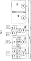
- Fig. 1 shows a basic system structure that can be used within the scope of the invention.
- the system structure shown is designed viewed topologically as a line, although a star topology or any mixed forms are also conceivable.
- a first bus participant is a monitoring module, e.g. a safety-related master, 100, hereinafter also referred to as a safety master, which in the present example is also the bus master, although this is not mandatory within the scope of the invention. This can generally be a specific, correspondingly specified security participant.
- a second and third bus subscriber is a safety-oriented slave output subscriber 200, also referred to below as an output module or safety output slave, or a safety-oriented slave input subscriber 300, also referred to below as a safety input slave.
- a fourth and fifth bus subscriber is a non-safety-oriented slave output subscriber 400, also referred to below as an output slave, or a non-safety-oriented slave input subscriber 500, also referred to as an input slave below.
- Safety-related participants i.e. participants who process safety-relevant process data, and non-safety-related participants can thus be mixed and also arranged as required.
- an emergency stop switch 110 is connected to the safety master 100, the safety-related input information of which the participant 100 receives redundantly via two inputs 121 and 122 and initially via two redundant inputs, depending on the protocol Processing channels 131 and 132 processed before a signal coupling to the bus 600 takes place.
- a motor 210 is connected to the safety output slave 200, whereby the participant 200, after a signal decoupling from the bus 600, initially carries out protocol-specific processing via two redundant processing channels 231 and 232 and sends the safety-relevant output information to the motor 210 via an output 220 .
- a protective door 311 and a speed sensor 312, for example, are connected to the safety input slave 300, the safety-relevant input information of which the participant 300 receives redundantly via two inputs 321 and 322 and processes it in a protocol-specific manner via a processing channel 330 before a signal is coupled to the bus 600.
- a safety-related function is therefore usually implemented using redundant processing, for example through two separate hardware channels, with the respective interface 140, 240, 340, 440 or 540 of a participant to the bus 600 usually only being implemented as a single channel is.
- this also enables twice the number of participants to be operated on the bus, in particular with regard to bus load, current consumption and capacity. Errors caused by the bus coupling, e.g. based on line drivers, galvanic isolation, can usually be recognized by the line protocol used.
- the processing unit of the safety-related subscribers does not necessarily have to be designed with two channels on the hardware side, but in many cases it is also sufficient if the software is designed with two channels.
- the bus 600 now provides the common data line for the method and transmission system according to the invention for sending and receiving all data, in particular process data.
- a LIN bus LIN: Local Interconnect Network
- a transmission system works in which, during certain data cycles, a master reads out protocol-specific data from field devices connected via subscribers and writes them into them during subsequent data cycles. with about 19.2 to 38 kbd.
- process input and output data are also transmitted, for example, at a fixed interval, each offset by half the bus cycle time.
- a transmission protocol for, for example, a cyclical transmission of process input and output data therefore often uses two different data exchange services, also referred to below as data exchange mode.
- a bus cycle consequently comprises a data cycle based on a PD read service and a subsequent data cycle based on a PD write service.
- a master When transferring process output data, a master basically sends all data for the connected field devices to the participants connected to it with the PD-Write service and then determines a CRC (Cyclic Redundancy Check), which it also transfers.
- the transmission system is expediently designed in such a way that all connected subscribers read all of the information transmitted in this way and preferably also form a CRC, which they use with the received CRC from the master compare, so that in the event of an error, an error message is generated and, for example, selected participants or individual field devices are transferred to a safe state.
- the master When transferring the process input data, the master first sends a broadcast address followed by a function code for a PD read service, for example.
- the other connected subscribers then place data from their connected field devices, that is to say in particular their process input data, bit by bit on the data line in the time slots provided for this in each case.
- the participants are in turn able to recognize all data by listening in on the data line and to calculate a CRC for this.
- FIG. 3 shows a block diagram of a monitoring system with an output module 201 and a monitoring module 203, which is in bidirectional connection with the output module 201.
- the monitoring system further comprises an output device 205, which is connected downstream of the output module 201, and a pass-through device 207, which is connected downstream of the monitoring module 203 and whose output is connected to the output device 205.
- the output device 205 comprises an output for outputting an output signal in response to a control signal which the output module 201 generates on the basis of an input signal supplied by the monitoring module 203. Before this, the output module 201 transmits the control signal for the purpose of checking to the monitoring module 203, which checks it for a deviation from an expected control signal.
- the monitoring module 203 instructs the penetration device 207, for example by means of a penetration signal, to output the output signal prevent.
- the penetration device 207 acts, for example, directly on the output device 205 and, for example, interrupts its control or data path in order to prevent the output of the output signal.
- the modules 201, 203, 205 and 207 do not necessarily have to be implemented in spatially separate designs. It is also conceivable that they are implemented on a printed circuit board. Instead of the bus system, a separate connection can also be provided for communication, e.g. across isolating distances.
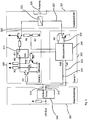
- Fig. 3 shows an output module with a bus coupling 301, a microcontroller circuit 303, a pass-through device 305 and an output device 307.
- the bus coupling 301 comprises an input to which, for example, a LIN bus can be coupled.
- the input is connected to a LIN bus driver 309, which has two connections 313 and 315.
- the connection 313 is connected via an input resistor R 1 of the penetration device 305 to a gate connection of a transistor T 1 of the penetration device 305.
- the transistor T 1 also has a first connection, for example an emitter connection, which is connected to ground.
- a second connection of the transistor T 1 for example a collector connection, is connected to a clock input A of a flip-flop 317, for example a monoflop.
- the second output of the transistor T 1 is connected to ground via a capacitor C 1 and to a supply potential via a resistor R 2.
- the flip-flop 317 further comprises a data input MR, which is connected to a second connection, for example a Collector connection of a second transistor T 2 is connected.
- a first connection of the transistor T 2 for example an emitter connection, is connected to ground.
- the data input MR can also be connected to a supply potential via a resistor R 3.
- a gate connection of the transistor T 2 is connected to a connection of the microcontroller 319 of the microcontroller circuit 303 via a resistor R 4.
- An output Q of the flip-flop 317 is connected via a resistor R 5 to a gate terminal of a third transistor T 3 , the first terminal of which, for example an emitter terminal, can be connected to a supply potential, and the second terminal of which can be connected to another via a resistor R 6 Port of the microcontroller 319 is connected.
- the resistor R 6 is connected to ground via a resistor R 7.
- the second connection of the third transistor T 3 simultaneously forms an output 323 of the penetration device 305, which is connected, for example, to an energy supply input of a relay 325 of the output device 307.
- the relay 325 includes a further path 327, which can be, for example, a data path or a control path.
- the relay 325 is also coupled to a switch 329.
- the switch 329 bridges two contacts as a function of a relay state, and an output signal can only be output when the switch is closed.
- the data path 327 of the relay 325 is connected to a second connection of a transistor T 4 , for example to a collector connection.
- the transistor T 4 also includes a second connection, for example an emitter connection, which is connected to ground.
- An output 329 of the microcontroller 319 is connected to a gate of the transistor T 4 .
- Another connection of the microcontroller 319 is furthermore connected to the second connection of the transistor T 4 via a resistor R 8 .
- connection 313 of the bus driver 309 is also connected to an input connection 331 of the microcontroller 319.
- an output connection 333 of the microcontroller is connected to connection 315.
- the microcontroller 319 receives data, for example an input signal, via the input connection 331 from an in Fig. 3 Monitoring module, not shown, and generates a control signal on its basis, which is fed to relay 325 via data path 327, for example. Before this, however, the microcontroller 319 sends the control signal to the monitoring module, not shown, via the output connection 333.
- the monitoring module checks whether the control signal corresponds to a control signal to be expected, for example on the basis of the input signal, ie the input data.
- the monitoring module transmits a penetration signal to the penetration device 305 via the connection 313 of the driver 309, on the basis of which, for example, as an alternative to the present invention, the energy supply of the relay 325 is interrupted, thereby closing the switch 329 is prevented or prevented. This prevents the output signal from being output.
- the structure of the in Fig. 3 The underlying concept shown in the output module is two-channel.
- the first channel is formed by the microcontroller circuit 303, while the penetration device 305 can be understood as a second channel, for example as an auxiliary channel.
- channel 2 that is to say the access device 305, of the output module is not necessarily a fully-fledged one Channel executed.
- the actual safety function is implemented, for example, by the microcontroller 319 of the microcontroller circuit 303.
- the microcontroller 319 can also be provided to implement the functional implementation of the bus protocol, the physical bus coupling, for example, by the in Fig. 3 LIN bus driver 309 shown can be produced.
- the processing of the safety function can begin with the received data.
- the microcontroller 329 controls the output device 307 (output stage) through the transistor T 4 , which can have a relay by way of example.
- the resistor R 8 is used to monitor the output stage 307, a monitoring result being published as a safety PDC by means of the microcontroller 319 in the next data cycle.
- the monitoring module (not shown) is able to check the microcontroller 319 and its output due to the known safety functions and the input data or input signals. If a discrepancy is detected, the monitoring module switches the system into a safe state by means of the superimposed security mechanism implemented by means of the access device 305.
- an analog output stage can also be used, for example, which is designed for a range between 4 mA and 20 mA, with its output current being less than 3 mA in the event of an error.
- Fig. 4 shows an example of a bus timing with a transmission cycle 400 that can be divided into three phases.
- the first phase 401 useful data are transmitted.
- the second phase 403 is used to check data on the frame and PDC level. If, for example, none of the participants discovers an error, the data signal of the LIN bus remains in the high-level state, which corresponds to a "high". If an error is detected, the subscriber concerned sends an error code, as is shown with the aid of data section 405. If no error was detected in the entire transmission and processing cycle including the checking of the output states of the safety outputs, the monitoring module, i.e. the master, generates an enable signal for the outputs, which is triggered by the monoflop 317 Fig. 3 is evaluated. The data verification takes place in section 403, for example. The output release is indicated by section 409.
- the monoflop 317 can, for example, be retriggered with a mono time of 30 ms. For example, it can only be triggered when the bus signal assumes a low level state, so-called “low”, represented by the output enable 409, for at least 700 microseconds, for example. However, this is not guaranteed during data transmission with a baud rate of at least 14400 baud, because the transmission of a stop bit at the end of each character forces at least a logical "1".
- the quiescent level of the LIN bus is also a logic "1", so that prolonged bus inactivity does not result in triggering.
- the "1" level on the LIN bus means that the in Fig. 3 illustrated transistor T 1 is turned on, which prevents or prevents charging of the capacitor C 1, so that no negative edge can occur at the input of the monoflop 317. Only a logical “low” blocks the transistor and leads to the capacitor C 1 being charged by the resistor R 2. After about 700 microseconds, the capacitor C 1 is charged to, for example, the “high” switching level of the monostable multivibrator 317, so that a triggering edge is generated at the monostable multivibrator 317 when the LIN bus signal changes from “low” to “high” . The output / Q is then switched to "Low", which leads to the output stage 307 being enabled.
- the microcontroller can check the switching transistor T 4 through the resistor R 8.
- the voltage divider comprising the resistors R 6 and R 7 is used to check the penetration device 305, which is implemented, for example, as an auxiliary channel. For the check, it can be advantageous to reset the monoflop 317 via the transistor T 2 , which leads to the transistor T 3 being blocked and thus the output stage 307 to be switched off.
- Fig. 5 shows a block diagram of an output module with a microcontroller circuit 501 and a penetration device 503.
- the microcontroller circuit 501 comprises a microcontroller 505 with a further penetration device 507.
- An input 509 of the output module is connected to a flip-flop 511, for example a monoflop, of the penetration device 503.
- the flip-flop 511 also has an output which, for example, with an in Fig. 5 output device, not shown, can be coupled.
- the input 509 is also connected to a reception input 513 of the microcontroller 505 and to an input 515 of the further penetration device 507.
- This comprises an input component 517 which is connected to an input of a flip-flop 519, for example a monoflop.
- a The output of the flip-flop 519 is connected to a connection of an output driver 521, for example an operational amplifier, of the further pass-through device 507.
- An output of the output driver 521 is connected to a gate of a transistor T 4 , the first connection of which, for example a collector connection, forms an output 523 of the microcontroller circuit 501.
- a second connection of the transistor T 4 for example a collector connection, is connected to ground.
- the second connection of the transistor T 4 is connected to an input element 525, for example an input driver, of the microcontroller 505 via a resistor R 8 by means of feedback.
- An output of the input element 525 is connected to a diagnostic element 527, which as in FIG Fig. 5 is connected to the flip-flop 511 shown.
- An output of the diagnostic element 527 is connected to a PDC producer 529, the output of which is connected to a bus element 531.
- the bus element 531 is also coupled to a UART 533 (UART: Universal Asynchronous Receiver / Transmitter). As in Fig. 5 the receiving input 513 is shown connected to an input of the UART 533.
- the UART 533 also has an output 535 which forms an output of the microcontroller circuit 501.
- the bus protocol element 531 is coupled to a PDC consumer 537, the output of which is connected to a safety function block 538.
- the safety function block 538 has an output which is connected to an input of the output element 5
- the further access device 507 can be implemented, for example, in software, while the access device 503 can be implemented in hardware.
- Further components implemented in hardware can include the UART element 533 and the input elements 517, 525 and the Be output element 521.
- the elements 527, 529, 531, 537, 519 and 538, on the other hand, can be implemented in software.
- the main signal path of the safety function leads from the UART block 533 through a protocol stack that is implemented in the bus protocol element 531.
- the data exchange between the bus protocol and the processing unit takes place, for example, by means of two buffers 529 and 537, the input data of the safety function being stored in the consumer PDC buffer 537. Accordingly, the output and status data are transferred to a monitoring module by the producer buffer 529, which is implemented in Fig. 5 is not shown, transferred.
- the output driver 521 of the microcontroller 505 has, as in FIG Fig. 5 shown, two inputs, whereby the safety function only uses the data or control input, for example. If the output driver 521 is enabled by the second input, this state is visible to the transistor T 4.
- the monoflop 519 realizes, for example, the same function as the pass-through device 503, which can also be referred to as a second channel or an auxiliary channel, with the difference that it can be implemented almost completely in software and thus ensures diversity.
- the pass-through device 503 and its monoflop function can also be implemented by a software function. This is particularly advantageous when a second microcontroller is used for more complex output modules.
Description
Die Erfindung betrifft ein Überwachungssystem zur Überwachung sicherheitsrelevanter Prozesse.The invention relates to a monitoring system for monitoring safety-relevant processes.
Das Dokument
Das Dokument
Das Dokument
Das Dokument
Ein industrielles, bei Datenübertragungssystemen eingesetztes Kommunikationssystem, das eine Vielzahl von angeschlossene Feldgeräte, wie Messfühler (Sensoren), Stellglieder und/oder Antriebe (Aktoren) mit einer Steuerungseinrichtung verbindet, ist bekanntermaßen ein Feldbus, wobei die Einrichtungen, welche die tatsächliche Verbindung zum Bus bereitstellen, als Bus-Teilnehmer bezeichnet werden.An industrial communication system used in data transmission systems, which connects a large number of connected field devices, such as measuring sensors (sensors), actuators and / or drives (actuators) with a control device, is known to be a field bus, the devices which provide the actual connection to the bus , are referred to as bus participants.
Bei einer Vielzahl von Applikationen ist hierbei die Deterministik, also die Vorbestimmtheit und Unabänderlichkeit bei der Übertragung von Prozessdaten wichtiger als die eigentliche Übertragungsgeschwindigkeit selbst. Bekannt sind beispielsweise Feldbusse mit daran angeschalteten Teilnehmern, bei welchen zum Übertragen von Prozessdaten zwischen einzelnen Teilnehmern, und also zum Senden und Empfangen von Prozessdaten, wie insbesondere Prozesseingangsdaten, Prozessausgangsdaten und Steuerungsdaten, eine zyklische Übertragung von Prozessdaten über einen gemeinsamen Übertragungskanal durchgeführt wird. Hierzu werden häufig während vorbestimmter Datenzyklen durch einen als Master fungierenden Teilnehmer protokollspezifische Daten von an Slave-Teilnehmern angeschlossenen Feldgeräten ausgelesen und während jeweils nachfolgender Datenzyklen in an Slave-Teilnehmer angeschlossene Feldgeräte hineingeschrieben.In a large number of applications, the deterministics, i.e. the predetermination and immutability in the transmission of process data, are more important than the actual transmission speed itself and receiving process data, such as in particular process input data, process output data and control data, a cyclical transmission of process data is carried out via a common transmission channel. For this purpose, protocol-specific data are often read out from field devices connected to slave participants during predetermined data cycles by a participant acting as a master and written into field devices connected to slave participants during subsequent data cycles.
Bei vielen Systemanwendungen sind die zu übertragenen Daten darüber hinaus zumindest teilweise sicherheitsrelevante Daten, so dass Fehler bei der Datenübertragung frühest möglichst erkannt werden müssen und bei Erkennen eines Fehlers zeitnah reagiert, z.B. ein Feldgerät, ein Teilnehmer oder ein (Teil-) System in einen sicheren Zustand überführt werden muss. Bei einer Übertragung sicherheitsrelevanter Daten über einen Bus sind im Wesentlichen sechs Fehlerklassen zu berücksichtigen. Diese betreffen die Wiederholung, den Verlust, die Einfügung, die falsche Abfolge, die Zerstörung und die Verzögerung von sicherheitsrelevanten Daten. Die Übertragung dieser Daten muss somit sicher sein.In many system applications, the data to be transmitted are also at least partially security-relevant data, so that errors in data transmission must be recognized as early as possible and when an error is recognized reacts promptly, e.g. a field device, a participant or a (sub) system has to be brought into a safe state. When transmitting safety-relevant data via a bus, there are essentially six error classes to be considered. These concern the repetition, loss, insertion, wrong sequence, destruction and delay of security-related data. The transmission of this data must therefore be secure.
Um eine sichere Übertragung von Daten, insbesondere von sicherheitsrelevanten Prozessdaten, zumindest derart zu gewährleisten, dass die aufgeführten Fehlerklassen bei Vorliegen auch erkannt werden können, ist es grundsätzlich gängige Praxis, die übertragenen Daten mit zusätzlichen Kontrolldaten, wie beispielsweise Zeitstempel, Teilnehmerinformation und/oder Checkinformation, z.B. CRCs (Cycle Redundancy Check) zu erweitern. Ein entscheidender Nachteil hierbei ist jedoch, dass der zu übertragende Overhead gegenüber den zu übertragenden Nutzdaten stark ansteigt und dadurch die Protokolleffizienz abnimmt. Besonders eklatant wird diese Schwäche, wenn nur wenige und/oder nur selten sicherheitsrelevante Nutzdaten pro Teilnehmer übertragen werden müssen. Ein weiterer Nachteil bisher bekannter Überwachungssysteme für sicherheitstechnische Daten liegt darin, dass zur Realisierung von teilnehmerspezifischen Prozessen mit sicherheitsgerichteten Ausgängen stets zumindest zwei Mikrocontroller bzw. komplexe Hardwareschaltungen zur Abarbeitung von komplexen Protokollpflichten notwendig sind.In order to ensure a secure transmission of data, in particular of security-relevant process data, at least in such a way that the listed error classes can also be recognized if they exist, it is generally common practice to add additional control data to the transmitted data, such as time stamps, subscriber information and / or check information , e.g. to extend CRCs (Cycle Redundancy Check). A decisive disadvantage here, however, is that the overhead to be transmitted increases sharply compared to the user data to be transmitted, and the protocol efficiency decreases as a result. This weakness becomes particularly blatant when only a few and / or only seldom security-relevant user data have to be transmitted per subscriber. Another disadvantage of previously known monitoring systems for safety-related data is that at least two microcontrollers or complex hardware circuits for processing complex protocol obligations are always required to implement user-specific processes with safety-related outputs.
Es ist die Aufgabe der vorliegenden Erfindung, ein Konzept zu schaffen, mit welchem der Hardware-, Software- bzw. der Qualifizierungsaufwand und somit die Herstellungskosten für Feldgeräte mit sicherheitsgerichteten Ausgängen gesenkt werden können.It is the object of the present invention to create a concept with which the hardware, software or qualification effort and thus the manufacturing costs for Field devices with safety-related outputs can be lowered.
Diese Aufgabe wird durch die Merkmale der unabhängigen Patentansprüche gelöst. Vorteilhafte Weiterbildungsformen sind in den nachgeordneten Patentansprüchen beschrieben. Die Erfindung basiert auf der Erkenntnis, dass die Verarbeitungsfunktionen eines Ausgangsmoduls, welches einen Gefährdungspotenzial enthaltenden Aktor steuert, einkanalig ausgeführt und zusätzlich durch ein separates Überwachungsmodul, beispielsweise durch ein Safety-Mastermodul, überwacht werden kann. Stellt das Überwachungsmodul eine Abweichung von erwartetem Verhalten oder eine Unregelmäßigkeit im Verarbeitungsablauf fest, so kann er das gesamte System, welches auch aus mehreren Ausgangsmodulen, beispielsweise aus mehreren Safety-Output-Modulen, bestehen kann, in einen sicheren Zustand überführen. Das Überführen des bzw. der Ausgangsmodule in den sicheren Zustand wird unabhängig von der jeweiligen Verarbeitungseinheit durch einen Hilfskanal realisiert, der den Durchgriff des Überwachungsmoduls ermöglicht und daher im Folgenden als Durchgriffseinrichtung bezeichnet wird.This object is achieved by the features of the independent patent claims. Advantageous forms of further training are described in the subordinate claims. The invention is based on the knowledge that the processing functions of an output module, which controls an actuator containing risk potential, can be implemented in one channel and can also be monitored by a separate monitoring module, for example by a safety master module. If the monitoring module detects a deviation from the expected behavior or an irregularity in the processing sequence, it can transfer the entire system, which can also consist of several output modules, for example several safety output modules, to a safe state. The transfer of the output module (s) to the safe state is implemented independently of the respective processing unit by an auxiliary channel which enables the monitoring module to penetrate and is therefore referred to below as a penetration device.
Somit wird die Sicherheitsfunktion auf das Überwachungsmodul (Safety-Master) und auf das Ausgangsmodul (Safety-Output-Modul) verteilt. Dabei wird der Safety-Master durch den einfachen und preiswerten Abschaltemechanismus der Durchgriffseinrichtung unterstützt. Ferner ist es vorteilhaft für die Funktionsweise des erfindungsgemäßen Konzeptes, den Ausgangsfreigabeimpuls beispielsweise in das Busprotokoll zu integrieren. Durch den Einsatz eines dezentralen Mikroprozessors ist es ferner möglich, die Steuerinformation für das Monoflop, welches einen Ausgang des Ausgangsmoduls bzw. einer geeingneten Ausgabeeinrichtung frei- bzw. abschaltet, zu integrieren. Die Steuerinformation kann beispielsweise zu festen Zeitpunkten in das Datensignal moduliert werden, wodurch eine effiziente Steuerung der Durchgriffseinrichtung möglich ist.The safety function is thus distributed to the monitoring module (safety master) and to the output module (safety output module). The safety master is supported by the simple and inexpensive switch-off mechanism of the access device. It is also advantageous for the functioning of the inventive concept to integrate the output enable pulse into the bus protocol, for example. By using a decentralized With the microprocessor, it is also possible to integrate the control information for the monoflop, which activates or deactivates an output of the output module or a suitable output device. The control information can, for example, be modulated into the data signal at fixed times, which enables efficient control of the penetration device.
Gemäß einem Aspekt betrifft die Erfindung ein Überwachungssystem mit einem Ausgangsmodul ausgebildet zum Erzeugen eines Steuersignals ansprechend auf ein Eingangssignal, einem Überwachungsmodul ausgebildet zum Erzeugen des Eingangssignals für das Ausgangsmodul, einer Ausgabeeinrichtung ausgebildet zum Ausgeben eines Ausgabesignals ansprechend auf das Steuersignal und einer Durchgriffseinrichtung zum Verhindern bzw. Unterbinden der Ausgabe des Ausgabesignals, wobei das Überwachungsmodul ausgebildet ist, das Steuersignal mit einem auf der Basis des Eingangssignals zu erwartenden Steuersignals zu vergleichen, um das Steuersignal auf ein Vorliegen einer Abweichung zu untersuchen. Das Überwachungsmodul und das Ausgabemodul sind separate Module. Ferner ist das Ausgangsmodul ausgebildet, das Steuersignal an das Überwachungsmodul auszusenden, und das Überwachungsmodul ist ausgebildet, das Steuersignal zu empfangen. Erfindungsgemäß ist das Überwachungsmodul weiterhin ausgebildet, bei Vorliegen einer Abweichung zwischen dem Steuersignal und dem zu erwartenden Steuersignal die Durchgriffseinrichtung anzuweisen, die Ausgabe des Ausgabesignals zu verhindern bzw. unterbinden, wobei die Durchgriffseinrichtung zum Unterbinden des Ausgebens des Ausgabesignals einen Steuer- oder Datenpfad der Ausgabeeinrichtung unterbrechend ausgebildet ist. Die Erfindung sieht weiter vor, dass das Überwachungsmodul ausgebildet ist, ein Freigabesignal zu erzeugen und an das Ausgangsmodul auszusenden, falls das Steuersignal dem zu erwartenden Steuersignal entspricht, wobei das Freigabesignal die Freigabe des Ausgabesignals anzeigt.According to one aspect, the invention relates to a monitoring system with an output module designed to generate a control signal in response to an input signal, a monitoring module designed to generate the input signal for the output module, an output device designed to output an output signal in response to the control signal and a penetration device for preventing or Preventing the output of the output signal, the monitoring module being designed to compare the control signal with a control signal to be expected on the basis of the input signal in order to examine the control signal for the presence of a deviation. The monitoring module and the output module are separate modules. Furthermore, the output module is designed to transmit the control signal to the monitoring module, and the monitoring module is designed to receive the control signal. According to the invention, the monitoring module is further designed, if there is a discrepancy between the control signal and the expected control signal, to instruct the penetration device to prevent or prevent the output of the output signal, the penetration device interrupting a control or data path of the output device to prevent the outputting of the output signal is trained. The invention further provides that the monitoring module is designed to generate a release signal and to send it to the output module if the control signal corresponds to the expected control signal, the release signal indicating the release of the output signal.
Gemäß einer Ausführungsform sind das Überwachungsmodul und das Ausgangsmodul oder die Durchgriffseinrichtung ausgebildet, über ein Kommunikationsnetzwerk, insbesondere über einen Kommunikationsbus, zu kommunizieren.According to one embodiment, the monitoring module and the output module or the penetration device are designed to communicate via a communication network, in particular via a communication bus.
Gemäß einer Ausführungsform ist die Durchgriffseinrichtung in dem Überwachungsmodul oder in dem Ausgangsmodul angeordnet.According to one embodiment, the penetration device is arranged in the monitoring module or in the output module.
Gemäß einer Ausführungsform umfasst die Ausgabeeinrichtung beispielsweise ein Relais oder eine analoge Ausgangsstufe mit einem Datenpfad zum Empfangen des Steuersignals und einem Energieversorgungspfad zum Versorgen der Ausgabeeinrichtung mit elektrischer Energie. Die analoge Ausgangsstufe kann beispielsweise für einen Bereich zwischen 4mA und 20mA ausgelegt sein, deren Ausgangsstrom bei einem Fehler kleiner als 3mA ist.According to one embodiment, the output device comprises, for example, a relay or an analog output stage with a data path for receiving the control signal and an energy supply path for supplying the output device with electrical energy. The analog output stage can, for example, be designed for a range between 4 mA and 20 mA, the output current of which is less than 3 mA in the event of an error.
Gemäß einer Ausführungsform umfasst die Durchgriffseinrichtung eine monostabile Kippstufe, insbesondere ein Flipflop oder ein Monoflop, wobei die Ausgabeeinrichtung einen Datenpfad und einen Energieversorgungspfad aufweist und wobei ein Ausgang der Kippstufe insbesondere über einen Ausgangstransistor mit dem Datenpfad oder mit dem Energieversorgungspfad zum Einwirken auf den Datenpfad oder auf den Energieversorgungspfad insbesondere ansprechend auf ein an einen Eingang der Kippstufe anlegbares Durchgriffssignal gekoppelt ist.According to one embodiment, the pass-through device comprises a monostable multivibrator, in particular a flip-flop or a monoflop, the output device having a data path and a power supply path, and wherein an output of the flip-flop in particular via an output transistor with the data path or with the energy supply path for acting on the data path or on the energy supply path is coupled in particular in response to a penetration signal that can be applied to an input of the flip-flop.
Gemäß einer Ausführungsform ist die Durchgriffseinrichtung ausgebildet, die Ausgabeeinrichtung ansprechend auf ein Durchgriffssignal in einen Sperrmodus zu überführen.According to one embodiment, the penetration device is designed to convert the output device into a blocking mode in response to a penetration signal.
Gemäß einer Ausführungsform umfasst das Ausgangsmodul einen Mikrocontroller, der vorgesehen ist, das Eingangssignal zu empfangen und das Steuersignal zu erzeugen.According to one embodiment, the output module comprises a microcontroller which is provided to receive the input signal and to generate the control signal.
Die Erfindung betrifft ein Verfahren zum Überwachen eines Ausgangsmoduls durch ein Überwachungsmodul, wobei durch das Ausgangsmodul ansprechend auf ein Eingangssignal ein Steuersignal erzeugt und an das Überwachungsmodul ausgesendet wird, wobei durch das Überwachungsmodul das Steuersignal empfangen wird und das Eingangssignals für das Ausgangsmodul erzeugt wird, wobei ansprechend auf das Steuersignal ein Ausgabesignal von einer Ausgabeeinrichtung ausgegeben wird und wobei das Steuersignal durch das Überwachungsmodul mit einem auf der Basis des Eingangssignals zu erwartenden Steuersignal verglichen wird, um das Steuersignal auf ein Vorliegen einer Abweichung hin zu untersuchen. Gemäß der Erfindung wird bei Vorliegen einer Abweichung zwischen dem Steuersignal und dem zu erwartenden Steuersignal eine Durchgriffseinrichtung von dem Überwachungsmodul mittels eines Durchgriffssignals angewiesen, die Ausgabe des Ausgabesignals zu unterbinden, wobei ein Steuer- oder Datenpfad der Ausgabeeinrichtung zum Unterbinden des Ausgebens des Ausgabesignals durch die Durchgriffseinrichtung unterbrochen wird und wobei ein Freigabesignal von dem Überwachungsmodul erzeugt wird und an das Ausgangsmodul ausgesendet wird, falls das Steuersignal dem zu erwartenden Steuersignal entspricht und wobei das Freigabesignal die Freigabe des Ausgabesignals anzeigt. Weitere Schritte des Verfahrens zum Überwachen des Ausgangsmoduls ergeben sich direkt aus der Funktionalität des erfindungsgemäßen Überwachungsmoduls.The invention relates to a method for monitoring an output module by a monitoring module, a control signal being generated by the output module in response to an input signal and being transmitted to the monitoring module, the control signal being received by the monitoring module and the input signal for the output module being generated, with responsive on the control signal an output signal is output by an output device and wherein the control signal is compared by the monitoring module with a control signal to be expected on the basis of the input signal in order to determine the presence of the control signal To investigate deviation. According to the invention, if there is a discrepancy between the control signal and the expected control signal, a pass-through device is instructed by the monitoring module by means of a pass-through signal to prevent the output of the output signal, with a control or data path of the output device for preventing the output signal from being output by the pass-through device is interrupted and a release signal is generated by the monitoring module and sent to the output module if the control signal corresponds to the expected control signal and the release signal indicates the release of the output signal. Further steps of the method for monitoring the output module result directly from the functionality of the monitoring module according to the invention.
Weitere Ausführungsbeispiele der Erfindung werden Bezug nehmend auf die beiliegenden Zeichnungen näher erläutert. Es zeigen:
- Fig. 1
- einen prinzipiellen Aufbau eines Überwachungssystems;
- Fig. 2
- ein Blockdiagramm eines Überwachungssystems;
- Fig. 3
- ein Blockdiagramm eines Ausgangsmoduls;
- Fig. 4
- eine Datenrahmenstruktur; und
- Fig. 5
- ein Blockdiagramm eines Ausgangsmoduls.
- Fig. 1
- a basic structure of a monitoring system;
- Fig. 2
- a block diagram of a monitoring system;
- Fig. 3
- a block diagram of an output module;
- Fig. 4
- a data frame structure; and
- Fig. 5
- a block diagram of an output module.
Nachfolgend wird zunächst auf
Zu sehen sind fünf an einen Bus 600 angeschaltete Bus-Teilnehmer. Ein erster Busteilnehmer ist ein Überwachungsmodul, z.B. ein sicherheitsgerichteter Master, 100, nachfolgend auch als Safety-Master bezeichnet, der im vorliegenden Beispiel gleichzeitig auch der Bus-Master ist, wobei dieses im Rahmen der Erfindung jedoch nicht zwingend ist. Es kann sich hierbei allgemein um einen bestimmten, entsprechend vorgegebenen Sicherheitsteilnehmer handeln. Ein zweiter und dritter Busteilnehmer ist ein sicherheitsgerichteter Slave-Ausgangsteilnehmer 200, nachfolgend auch als Ausgabemodul oder Safety-Output-Slave bezeichnet, bzw. ein sicherheitsgerichteter Slave-Eingangsteilnehmer 300, nachfolgend auch als Safety-Input-Slave bezeichnet. Ein vierter und fünfter Busteilnehmer ist ein nicht sicherheitsgerichteter Slave-Ausgangsteilnehmer 400, nachfolgend auch als Output-Slave bezeichnet, bzw. ein nicht sicherheitsgerichteter Slave-Eingangsteilnehmer 500, nachfolgend auch als Input-Slave bezeichnet. Sicherheitsgerichtete Teilnehmer, d.h. Teilnehmer, welche sicherheitsrelevante Prozessdaten verarbeiten, und nicht sicherheitsgerichtete Teilnehmer können somit gemischt werden und auch beliebig angeordnet sein.You can see five bus users connected to a
Hinsichtlich der sicherheitsgerichteten Teilnehmer des dargestellten beispielhaften Systemaufbaus ist an den Safety-Master 100 z.B. ein Not-Aus-Schalter 110 angeschaltet, dessen sicherheitsrelevante Eingangsinformation der Teilnehmer 100 über zwei Eingänge 121 und 122 redundant erhält und protokollspezifisch zunächst über zwei redundante Verarbeitungskanäle 131 und 132 verarbeitet, bevor eine Signalankopplung an den Bus 600 erfolgt. An den Safety-Output-Slave 200 ist z.B. ein Motor 210 angeschaltet, wobei der Teilnehmer 200 nach einer Signalauskopplung vom Bus 600 zunächst protokollspezifisch eine Verarbeitung über zwei redundante Verarbeitungskanäle 231 und 232 durchführt und die sicherheitsrelevante Ausgangsinformation an den Motor 210 über einen Ausgang 220 gibt. An den Safety-Input-Slave 300 sind z.B. eine Schutztür 311 und ein Drehzahlgeber 312 angeschaltet, deren sicherheitsrelevante Eingabeinformation der Teilnehmer 300 über zwei Eingänge 321 und 322 redundant erhält und protokollspezifisch über einen Verarbeitungskanal 330 verarbeitet, bevor eine Signalankopplung an den Bus 600 erfolgt.With regard to the safety-related participants of the exemplary system structure shown, an
Die Realisierung einer sicherheitsgerichteten Funktion erfolgt somit in der Regel unter Nutzung einer redundanten Verarbeitung, z.B. durch zwei hardwareseitig von einander getrennte Kanäle, wobei die jeweilige Schnittstelle 140, 240, 340, 440 bzw. 540 eines Teilnehmers zum Bus 600 in der Regel nur einkanalig realisiert ist. Neben einer Reduzierung des benötigten Platzes und der Kosten können hierdurch auch die doppelte Anzahl an Teilnehmern am Bus, insbesondere hinsichtlich Buslast, Stromaufnahme und Kapazität, betrieben werden. Fehler, die durch die Busankopplung, z.B. basierend auf Leitungstreiber, galvanischer Trennung, verursacht werden, können üblicherweise durch das verwendete Leitungsprotokoll erkannt werden. Die Verarbeitungseinheit der sicherheitsgerichteten Teilnehmer muss hardwareseitig jedoch nicht zwangsläufig zweikanalig ausgebildet sein, sondern in vielen Fällen reicht es auch, wenn die Software zweikanalig ausgeführt ist.A safety-related function is therefore usually implemented using redundant processing, for example through two separate hardware channels, with the
Der Bus 600 stellt nunmehr die gemeinsame Datenleitung für das erfindungsgemäße Verfahren und Übertragungssystem zum Senden und Empfangen von allen Daten, insbesondere von Prozessdaten bereit. Beispielsweise basierend auf einem aus der Automobiltechnik bekannten LIN-Bus (LIN: Local Interconnect Network) arbeitet ein derartiges Übertragungssystem, bei welchem während bestimmter Datenzyklen durch einen Master protokollspezifische Daten von über Teilnehmer angeschlossenen Feldgeräten ausgelesen und während jeweils nachfolgender Datenzyklen in solche hineingeschrieben werden können, mit etwa 19,2 bis 38 kbd.The
Bei einem beispielhaften Verfahren nach der Erfindung erfolgt die Übertragung von Prozesseingangs- und -ausgangsdaten beispielsweise auch in einem festen Intervall, jeweils um die halbe Buszykluszeit versetzt. Ein Übertragungsprotokoll für beispielsweise eine zyklische Übertragung von Prozesseingangs- und -ausgangsdaten verwendet somit häufig zwei unterschiedliche Datenaustauschdienste, nachfolgend auch als Data-Exchange-Mode bezeichnet. Ein Buszyklus umfasst in diesem Fall folglich einen auf einem PD-Read-Dienst basierten Datenzyklus und einen nachfolgenden Datenzyklus, der auf einem PD-Write-Dienst basiert.In an exemplary method according to the invention, process input and output data are also transmitted, for example, at a fixed interval, each offset by half the bus cycle time. A transmission protocol for, for example, a cyclical transmission of process input and output data therefore often uses two different data exchange services, also referred to below as data exchange mode. In this case, a bus cycle consequently comprises a data cycle based on a PD read service and a subsequent data cycle based on a PD write service.
Bei der Übertragung von Prozessausgangsdaten sendet ein Master an die mit diesem verbundenen Teilnehmer beim PD-Write-Dienst grundsätzlich alle Daten für die angeschlossenen Feldgeräte und ermittelt anschließend einen CRC (Cyclic Redundancy Check), den er auch überträgt. Zweckmäßigerweise ist das Übertragungssystem derart ausgebildet, dass alle angeschlossenen Teilnehmer alle so übertragenden Informationen mitlesen und bevorzugt ebenfalls einen CRC bilden, den sie mit dem empfangenen CRC des Masters vergleichen, so dass im Fehlerfall eine Fehlermeldung generiert und beispielsweise ausgewählte Teilnehmer oder einzelne Feldgeräte in einen sicheren Zustand überführt werden. Bei der Übertragung der Prozesseingangsdaten sendet der Master bei einem PD-Read-Dienst z.B. zunächst eine Broadcast-Adresse gefolgt von einem Funktionscode. Die weiteren angeschlossenen Teilnehmer legen daraufhin Daten ihrer angeschalteten Feldgeräte, also insbesondere ihre Prozesseingangsdaten Bit für Bit auf die Datenleitung in jeweils dafür vorgesehene Zeitschlitze. In bevorzugter Ausführung sind die Teilnehmer wiederum in der Lage durch Mithören auf der Datenleitung alle Daten zu erkennen und hierfür wiederum einen CRC zu berechnen.When transferring process output data, a master basically sends all data for the connected field devices to the participants connected to it with the PD-Write service and then determines a CRC (Cyclic Redundancy Check), which it also transfers. The transmission system is expediently designed in such a way that all connected subscribers read all of the information transmitted in this way and preferably also form a CRC, which they use with the received CRC from the master compare, so that in the event of an error, an error message is generated and, for example, selected participants or individual field devices are transferred to a safe state. When transferring the process input data, the master first sends a broadcast address followed by a function code for a PD read service, for example. The other connected subscribers then place data from their connected field devices, that is to say in particular their process input data, bit by bit on the data line in the time slots provided for this in each case. In a preferred embodiment, the participants are in turn able to recognize all data by listening in on the data line and to calculate a CRC for this.
Die Module 201, 203, 205 und 207 müssen nicht zwingend in räumlich getrennten Bauformen realisiert werden. Es ist auch denkbar, dass sie auf einer Leiterplatte realisiert werden. Statt des Bussystems kann ferner zur Kommunikation eine getrennte Verbindung, z.B. über Trennstrecken hinweg, vorgesehen werden.The
Das Flipflop 317 umfasst ferner einen Dateneingang MR, der mit einem zweiten Anschluss, beispielsweise einem Kollektoranschluss, eines zweiten Transistors T2 verbunden ist. Ein erster Anschluss des Transistors T2, beispielsweise ein Emitteranschluss, ist hingegen mit Masse verbunden. Der Dateneingang MR ist ferner über einen Widerstand R3 mit einem Versorgungspotential verbindbar. Ein Gate-Anschluss des Transistors T2 ist über einen Widerstand R4 mit einem Anschluss des Mikrocontrollers 319 des Mikrocontrollerschaltkreises 303 verbunden. Ein Ausgang Q des Flipflops 317 ist über einen Widerstand R5 mit einem Gate-Anschluss eines dritten Transistors T3 verbunden, dessen erster Anschluss, beispielsweise ein Emitteranschluss, mit einem Versorgungspotential verbindbar ist, und dessen zweiter Anschluss über einen Widerstand R6 mit einem weiteren Anschluss des Mikrocontrollers 319 verbunden ist. Der Widerstand R6 ist über einen Widerstand R7 mit Masse verbunden. Der zweite Anschluss des dritten Transistors T3 bildet gleichzeitig einen Ausgang 323 der Durchgriffseinrichtung 305, der beispielsweise mit einem Energieversorgungseingang eines Relais 325 der Ausgabeeinrichtung 307 verbunden ist. Das Relais 325 umfasst einen weiteren Pfad 327, bei dem es sich beispielsweise um einen Datenpfad bzw. um einen Steuerungspfad handeln kann. Das Relais 325 ist ferner mit einem Schalter 329 gekoppelt. Der Schalter 329 überbrückt in Abhängigkeit von einem Relaiszustand zwei Kontakte, wobei nur im geschlossenen Schalterzustand ein Ausgabesignal ausgegeben werden kann.The flip-
Der Datenpfad 327 des Relais 325 ist mit einem zweiten Anschluss eines Transistors T4 verbunden, beispielsweise mit einem Kollektoranschluss. Der Transistor T4 umfasst ferner einen zweiten Anschluss, beispielsweise einen Emitteranschluss, der mit Masse verbunden ist. Dabei ist ein Ausgang 329 des Mikrocontrollers 319 mit einem Gate des Transistors T4 verbunden. Ein weiterer Anschluss des Mikrocontrollers 319 ist ferner über einen Widerstand R8 mit dem zweiten Anschluss des Transistors T4 verbunden.The
Der Anschluss 313 des Bustreibers 309 ist ferner mit einem Eingangsanschluss 331 des Mikrocontrollers 319 verbunden. Ein Ausgangsanschluss 333 des Mikrocontrollers ist hingegen mit dem Anschluss 315 verbunden. Der Mikrocontroller 319 empfängt Daten, beispielsweise ein Eingangssignal, über den Eingangsanschluss 331 von einem in
Das der Struktur des in
Nachdem beispielsweise ein Protokollframe korrekt empfangen wurde und alle PDCs (PDC: Process Data Channel) die Plausibilitätsüberprüfungen absolviert haben, kann die Abarbeitung der Sicherheitsfunktion mit den empfangenen Daten beginnen. Dabei steuert der Mikrocontroller 329 durch den Transistor T4 die Ausgabeeinrichtung 307 (Ausgangsstufe), welche exemplarisch ein Relais aufweisen kann. Der Widerstand R8 dient dabei zur Überwachung der Ausgangsstufe 307, wobei ein Überwachungsergebnis mittels des Mikrocontrollers 319 im nächsten Datenzyklus als Sicherheits-PDC (Safety-PDC) veröffentlicht wird. Das in
Alternativ zum dargestellten Relais kann z.B. auch eine analoge Ausgangsstufe eingesetzt werden, die beispielsweise für einen Bereich zwischen 4mA und 20mA ausgelegt ist, wobei deren Ausgangsstrom bei einem Fehler kleiner als 3mA ist.As an alternative to the relay shown, an analog output stage can also be used, for example, which is designed for a range between 4 mA and 20 mA, with its output current being less than 3 mA in the event of an error.
Das Monoflop 317 (IC 1) ist beispielsweise retriggerbar mit einer Monozeit von 30 ms. Es kann beispielsweise nur dann getriggert werden, wenn das Bussignal für beispielsweise mindestens 700 µs einen Niederpegelzustand, sog. "Low", dargestellt durch die Ausgangsfreigabe 409, annimmt. Während einer Datenübertragung mit einer Baudrate von mindestens 14400 Baud ist dieses jedoch nicht gewährleistet, weil durch die Übertragung eines Stopp-Bits am Ende jedes Zeichens mindestens eine logische "1" erzwungen wird. Der Ruhepegel des LIN-Busses ist ebenfalls logisch "1", so dass eine längere Businaktivität zu keiner Triggerung führt.The monoflop 317 (IC 1) can, for example, be retriggered with a mono time of 30 ms. For example, it can only be triggered when the bus signal assumes a low level state, so-called “low”, represented by the output enable 409, for at least 700 microseconds, for example. However, this is not guaranteed during data transmission with a baud rate of at least 14400 baud, because the transmission of a stop bit at the end of each character forces at least a logical "1". The quiescent level of the LIN bus is also a logic "1", so that prolonged bus inactivity does not result in triggering.
Der "1"-Pegel auf dem LIN-Bus führt dazu, dass der in
Der Eingang 509 ist ferner mit einem Empfangseingang 513 des Mikrocontrollers 505 sowie mit einem Eingang 515 der weiteren Durchgriffseinrichtung 507 verbunden. Diese umfasst ein Eingangsbauelement 517, das mit einem Eingang eines Flipflops 519, beispielsweise eines Monoflops, verbunden ist. Ein Ausgang des Flipflops 519 ist mit einem Anschluss eines Ausgangstreibers 521, beispielsweise eines Operationsverstärkers, der weiteren Durchgriffseinrichtung 507 verbunden. Ein Ausgang des Ausgangstreibers 521 ist mit einem Gate eines Transistors T4 verbunden, dessen erster Anschluss, beispielsweise ein Kollektoranschluss, einen Ausgang 523 der Mikrocontrollerschaltung 501 bildet. Ein zweiter Anschluss des Transistors T4, beispielsweise ein Kollektoranschluss, ist hingegen mit Masse verbunden. Der zweite Anschluss des Transistors T4 ist über einen Widerstand R8 mittels einer Rückkopplung mit einem Eingangselement 525, beispielsweise einem Eingangstreiber, des Mikrocontrollers 505 verbunden. Ein Ausgang des Eingangselementes 525 ist mit einem Diagnoseelement 527 verbunden, das wie in
Die weitere Durchgriffseinrichtung 507 kann beispielsweise in Software realisiert werden, während die Durchgriffseinrichtung 503 in Hardware realisiert werden kann. Weitere in Hardware realisierte Komponenten können das UART-Element 533 sowie die Eingangselemente 517, 525 und das Ausgangselement 521 sein. Die Elemente 527, 529, 531, 537, 519 sowie 538 können hingegen in Software realisiert sein.The
Der Hauptsignalpfad der Sicherheitsfunktion führt von dem UART-Block 533 durch einen Protokoll-Stack, der in dem Busprotokollelement 531 realisiert ist. Der Datenaustausch zwischen dem Busprotokoll und der Verarbeitungseinheit geschieht beispielsweise mittels zwei Buffer 529 und 537, wobei die Eingangsdaten der Sicherheitsfunktion im Consumer-PDC-Buffer 537 gespeichert werden. Dementsprechend werden die Ausgangs- und die Statusdaten durch den Producer-Buffer 529 zu einem Überwachungsmodul, das in
Der Ausgangstreiber 521 des Mikrocontrollers 505 hat, wie in
Alternativ zu dem in
Claims (8)
- A monitoring system, comprising:an output module (201) adapted to generate a control signal in response to an input signal; a monitoring module (203) adapted to generate the input signal for the output module (201),the monitoring module (203) and the output module (201) being separate modules;an output device (205) adapted to output an output signal in response to the control signal; anda crack-down device (207) for inhibiting the output of the output signal;wherein the output module (201) is adapted to transmit the control signal to the monitoring module (203), and the monitoring module (203) is adapted to receive the control signal;wherein the monitoring module (203) is adapted to compare the control signal with a control signal to be expected on the basis of the input signal in order to check the control signal for the presence of a discrepancy;characterized in thatin the presence of a discrepancy between the control signal and the expected control signal, the monitoring module (203) is adapted to instruct the crack-down device (207) to inhibit the output of the output signal, by sending a crack-down signal to the crack-down device (207);wherein the crack-down device (207) is adapted to interrupt a control or data path of the output device (205) to inhibit the output of the output signal; andif the control signal corresponds to the expected control signal, the monitoring module (203) is adapted to generate an release signal and to transmit it to the output module (201), wherein the release signal indicates the release of the output signal.
- The monitoring system according to claim 1, wherein the monitoring module (203) and the output module (201) or the crack-down device (207) are adapted to communicate via a communication network, in particular via a communication bus.
- The monitoring system according to any one of the preceding claims, wherein the crack-down device (207) is provided in the monitoring module (203) or in the output module (201).
- The monitoring system according to any one of the preceding claims, wherein the output device (205) includes a relay or an analog output stage including a data path for receiving the control signal and including an power supply path for supplying electrical power to the output device.
- The monitoring system according to any one of the preceding claims, wherein the crack-down device (207) includes a monostable multivibrator, in particular a flip-flop or a monoflop, wherein the output device (205) includes a data path and a power supply path, and wherein an output of the multivibrator is coupled to the data path, in particular via an output transistor, for acting on the data path in particular in response to a crack-down signal that can be applied to an input of the multivibrator.
- The monitoring system according to any one of the preceding claims, wherein the crack-down device (207) is adapted to transfer the output device (205) into a blocked mode in response to a crack-down signal.
- The monitoring system according to any one of the preceding claims, wherein the output module (201) includes a microcontroller that is intended for receiving the input signal and for generating the control signal.
- A method for monitoring an output module (201) by a separate monitoring module (203),wherein a control signal is generated by the output module (201) in response to an input signal and is transmitted to the monitoring module (203), wherein the monitoring module (203) receives the control signal and generates the input signal for the output module (201), wherein in response to the control signal an output signal is output by an output device (205), and wherein the control signal is compared with a control signal to be expected on the basis of the input signal, by the monitoring module (203), in order to check the control signal for the presence of a discrepancy;characterized in thatin the presence of a discrepancy between the control signal and the expected control signal, the monitoring module (203) instructs a crack-down device (207) to inhibit the output of the output signal, by means of a crack-down signal, and wherein, for inhibiting the output of the output signal, a control or data path of the output device (205) is interrupted by the crack-down device (207); and if the control signal corresponds to the expected control signal, a release signal is generated by the monitoring module (203) and is transmitted to the output module (201), and wherein the release signal indicates the release of the output signal.
Applications Claiming Priority (2)
| Application Number | Priority Date | Filing Date | Title |
|---|---|---|---|
| DE102008029948.0A DE102008029948B4 (en) | 2008-06-26 | 2008-06-26 | monitoring system |
| PCT/EP2009/004516 WO2009156122A1 (en) | 2008-06-26 | 2009-06-23 | Monitoring system |
Publications (2)
| Publication Number | Publication Date |
|---|---|
| EP2297619A1 EP2297619A1 (en) | 2011-03-23 |
| EP2297619B1 true EP2297619B1 (en) | 2021-11-03 |
Family
ID=41090591
Family Applications (1)
| Application Number | Title | Priority Date | Filing Date |
|---|---|---|---|
| EP09768971.5A Active EP2297619B1 (en) | 2008-06-26 | 2009-06-23 | Monitoring system |
Country Status (7)
| Country | Link |
|---|---|
| US (1) | US8744805B2 (en) |
| EP (1) | EP2297619B1 (en) |
| JP (1) | JP5490112B2 (en) |
| CN (1) | CN102077148B (en) |
| DE (1) | DE102008029948B4 (en) |
| RU (1) | RU2504813C2 (en) |
| WO (1) | WO2009156122A1 (en) |
Families Citing this family (6)
| Publication number | Priority date | Publication date | Assignee | Title |
|---|---|---|---|---|
| DE102012016269A1 (en) | 2012-08-17 | 2014-02-20 | Abb Ag | Electric machine with a monitoring device |
| ES2593831T3 (en) * | 2013-02-13 | 2016-12-13 | Phoenix Contact Gmbh & Co. Kg | Data control and transmission system for transmitting safety related data through a fieldbus |
| DE102013217063A1 (en) * | 2013-08-27 | 2015-03-05 | E.G.O. Elektro-Gerätebau GmbH | Appliances Control |
| CN104702333B (en) * | 2015-01-14 | 2017-10-03 | 西安爱生技术集团公司 | A kind of UAV TT & C's signal distributor and distribution method |
| DE102016106531A1 (en) * | 2016-04-08 | 2017-10-12 | Eaton Electrical Ip Gmbh & Co. Kg | Bus subscriber and method for operating a bus subscriber |
| DE102020128026A1 (en) * | 2020-10-23 | 2022-04-28 | Pilz Gmbh & Co. Kg | Control device with protection module |
Family Cites Families (30)
| Publication number | Priority date | Publication date | Assignee | Title |
|---|---|---|---|---|
| US2883255A (en) * | 1954-04-28 | 1959-04-21 | Panellit Inc | Automatic process logging system |
| US3237164A (en) * | 1962-06-29 | 1966-02-22 | Control Data Corp | Digital communication system for transferring digital information between a plurality of data processing devices |
| US3337773A (en) * | 1964-11-06 | 1967-08-22 | Barber Colman Co | Overload prevention for control systems |
| US3421069A (en) * | 1966-08-04 | 1969-01-07 | Brunswick Corp | Regulated power supply including a blocking oscillator and trigger means to turn off the oscillator |
| CA850273A (en) * | 1967-07-06 | 1970-08-25 | Charles J. Clarke, Jr. | D. d. c. interfacing circuitry |
| US3516072A (en) * | 1967-09-18 | 1970-06-02 | Susquehanna Corp | Data collection system |
| CA825823A (en) * | 1968-02-09 | 1969-10-21 | A. Hogan James | Electronic process controller |
| DE3538484A1 (en) * | 1985-10-25 | 1987-05-07 | Siemens Ag | METHOD FOR CHECKING PROTECTIVE COMMAND TRANSMISSION SYSTEMS IN ONLINE OPERATION |
| RU2099764C1 (en) * | 1994-11-30 | 1997-12-20 | Акционерное общество открытого типа "Хлебокомбинат Восход" | Manufacturing mode maintaining apparatus |
| JP3297249B2 (en) | 1995-05-26 | 2002-07-02 | 三菱電機株式会社 | Control method for distributed remote I / O control system |
| US6243629B1 (en) | 1996-04-19 | 2001-06-05 | Honda Giken Kogyo Kabushiki Kaisha | Electronic control unit for automotive vehicles |
| JP3716948B2 (en) | 1996-04-19 | 2005-11-16 | 本田技研工業株式会社 | Automotive electronic control unit |
| DE19718284C2 (en) * | 1997-05-01 | 2001-09-27 | Kuka Roboter Gmbh | Method and device for monitoring a system with several functional units |
| US6028491A (en) * | 1998-04-29 | 2000-02-22 | Atmel Corporation | Crystal oscillator with controlled duty cycle |
| DE19860358B4 (en) | 1998-12-24 | 2008-05-08 | Wratil, Peter, Dr. | Method for error suppression in output units in control devices |
| DE19913279B4 (en) | 1999-03-24 | 2006-07-27 | Wratil, Peter, Dr. | Control device with monitoring unit for error detection and error suppression |
| JP3716664B2 (en) * | 1999-04-19 | 2005-11-16 | 三菱電機株式会社 | Automotive electronic control unit with self-monitoring function |
| JP3752884B2 (en) * | 1999-04-19 | 2006-03-08 | 三菱電機株式会社 | Automotive electronic control unit with self-monitoring function |
| DE10008434A1 (en) | 2000-02-23 | 2001-09-20 | Phoenix Contact Gmbh & Co | Method and device for monitoring security in an automation control device includes an automation device with a controller and a central monitoring device with direct in- and output devices and a serial bus connection. |
| RU32615U1 (en) * | 2003-04-28 | 2003-09-20 | Кушев Дмитрий Владимирович | Safe management and control system |
| JP4451712B2 (en) * | 2004-05-18 | 2010-04-14 | 富士通マイクロエレクトロニクス株式会社 | Data transfer apparatus and transfer abnormal state detection method. |
| CN1588762A (en) * | 2004-09-28 | 2005-03-02 | 张瑞棉 | Micro power energy saving environment protection generator |
| DE102004061013A1 (en) | 2004-12-18 | 2006-07-06 | Bosch Rexroth Aktiengesellschaft | Safe input / output module for a controller |
| US8055814B2 (en) | 2005-03-18 | 2011-11-08 | Rockwell Automation Technologies, Inc. | Universal safety I/O module |
| EP1911058B1 (en) | 2005-08-02 | 2008-12-03 | Phoenix Contact GmbH & Co. KG | Safety switching unit for controlling a safety device into a safe state |
| DE102006001805A1 (en) | 2006-01-12 | 2007-07-19 | Phoenix Contact Gmbh & Co. Kg | Safety switching device for controlling e.g. three-phase motor, has microprocessor determining whether amplitude of analog signal lies outside of operating range, where microprocessor is component of safety device for controlling of drive |
| DE102006020793A1 (en) * | 2006-05-03 | 2007-11-08 | Ab Skf | Circuit arrangement and method for operating a circuit arrangement |
| KR100809703B1 (en) * | 2006-09-22 | 2008-03-06 | 삼성전자주식회사 | Pass gate circuit and its controlling method for stable transferring of signals |
| WO2008037495A2 (en) | 2006-09-28 | 2008-04-03 | Pepperl + Fuchs Gmbh | Bus system, and method for the operation thereof |
| DE102006056420B4 (en) * | 2006-11-28 | 2012-11-29 | Wago Verwaltungsgesellschaft Mbh | Security module and automation system |
-
2008
- 2008-06-26 DE DE102008029948.0A patent/DE102008029948B4/en active Active
-
2009
- 2009-06-23 WO PCT/EP2009/004516 patent/WO2009156122A1/en active Application Filing
- 2009-06-23 CN CN200980124498.XA patent/CN102077148B/en active Active
- 2009-06-23 JP JP2011515190A patent/JP5490112B2/en not_active Expired - Fee Related
- 2009-06-23 EP EP09768971.5A patent/EP2297619B1/en active Active
- 2009-06-23 RU RU2011102770/08A patent/RU2504813C2/en not_active IP Right Cessation
- 2009-06-23 US US12/997,748 patent/US8744805B2/en active Active
Also Published As
| Publication number | Publication date |
|---|---|
| DE102008029948A1 (en) | 2010-01-21 |
| DE102008029948B4 (en) | 2018-08-30 |
| RU2504813C2 (en) | 2014-01-20 |
| CN102077148A (en) | 2011-05-25 |
| EP2297619A1 (en) | 2011-03-23 |
| JP5490112B2 (en) | 2014-05-14 |
| RU2011102770A (en) | 2012-08-10 |
| JP2011525667A (en) | 2011-09-22 |
| WO2009156122A1 (en) | 2009-12-30 |
| US8744805B2 (en) | 2014-06-03 |
| CN102077148B (en) | 2015-05-13 |
| US20110128046A1 (en) | 2011-06-02 |
Similar Documents
| Publication | Publication Date | Title |
|---|---|---|
| EP1738382B2 (en) | Safety switch for a fail-safe circuit | |
| EP2297619B1 (en) | Monitoring system | |
| WO2004029737A1 (en) | Redundant control unit arrangement | |
| EP2145430B1 (en) | Method and system for the secure transmission of process data to be cyclically transmitted | |
| EP2356528B1 (en) | Method for transferring data in an automated control system | |
| WO2016008948A1 (en) | Control and data-transfer system, gateway module, i/o module, and method for process control | |
| EP1533673A2 (en) | control system | |
| WO2008053039A1 (en) | Device and method for manipulating communication messages | |
| EP1989470B1 (en) | Safety concept for a transmission actuator device | |
| DE102006002824B4 (en) | Method and device for converting multichannel messages into a single-channel secure message | |
| WO2011048145A1 (en) | Automation system and method for operating an automation system | |
| WO2020229221A1 (en) | Transmitting/receiving device and communication control device for a subscriber station of a serial bus system, and method for communication in a serial bus system | |
| EP3100121A1 (en) | Method and apparatus for safely disconnecting an electrical load | |
| DE102012210126A1 (en) | Method for operating a network arrangement, network device and network arrangement | |
| DE102011051629B3 (en) | Safety bus system has master and slave arrangement that transmits bus signals in form of data messages over bus lines, and safety monitor is provided for performing error checks | |
| DE10232272B4 (en) | Method for operating a device for a security system | |
| DE102004035901B4 (en) | Device for controlling a safety-critical process | |
| EP1064590B1 (en) | Shortened data message of an automation system | |
| EP2767877B1 (en) | Control and data transmission system for transmission of safety-related data via a field bus | |
| EP3915227B1 (en) | Transmitting/receiving device for a subscriber station of a serial bus system, and method for communication in a serial bus system | |
| EP3742680B1 (en) | Adjustment device and corresponding method | |
| DE102022000991A1 (en) | Automation system and method for operating an automation system | |
| DE102008064761B3 (en) | Method for asynchronously transmitting control signals from transmitter to receiver, involves logically combining control signals with each other at receiver end, where logic combination result is transmitted to transmitter end | |
| DE102009028103A1 (en) | Method for performing communication between output of e.g. control device, and device outside control device, involves transferring information between serial peripheral interface bus and communication connection | |
| DD240457A1 (en) | INFORMATION PROCESSING SYSTEM WITH HIGH LEVEL OF RELIABILITY AND SAFETY |
Legal Events
| Date | Code | Title | Description |
|---|---|---|---|
| PUAI | Public reference made under article 153(3) epc to a published international application that has entered the european phase |
Free format text: ORIGINAL CODE: 0009012 |
|
| 17P | Request for examination filed |
Effective date: 20110114 |
|
| AK | Designated contracting states |
Kind code of ref document: A1 Designated state(s): AT BE BG CH CY CZ DE DK EE ES FI FR GB GR HR HU IE IS IT LI LT LU LV MC MK MT NL NO PL PT RO SE SI SK TR |
|
| AX | Request for extension of the european patent |
Extension state: AL BA RS |
|
| DAX | Request for extension of the european patent (deleted) | ||
| 17Q | First examination report despatched |
Effective date: 20160701 |
|
| STAA | Information on the status of an ep patent application or granted ep patent |
Free format text: STATUS: EXAMINATION IS IN PROGRESS |
|
| R17C | First examination report despatched (corrected) |
Effective date: 20160701 |
|
| STAA | Information on the status of an ep patent application or granted ep patent |
Free format text: STATUS: EXAMINATION IS IN PROGRESS |
|
| GRAP | Despatch of communication of intention to grant a patent |
Free format text: ORIGINAL CODE: EPIDOSNIGR1 |
|
| STAA | Information on the status of an ep patent application or granted ep patent |
Free format text: STATUS: GRANT OF PATENT IS INTENDED |
|
| RIC1 | Information provided on ipc code assigned before grant |
Ipc: G06F 17/40 20060101ALN20210511BHEP Ipc: G05B 9/02 20060101ALI20210511BHEP Ipc: G05B 19/042 20060101AFI20210511BHEP |
|
| INTG | Intention to grant announced |
Effective date: 20210526 |
|
| RBV | Designated contracting states (corrected) |
Designated state(s): AT BE BG CH CY CZ DK EE ES FI FR GB GR HR HU IE IS IT LI LT LU LV MC MK MT NL NO PL PT RO SE SI SK TR |
|
| REG | Reference to a national code |
Ref country code: DE Ref legal event code: R108 |
|
| GRAS | Grant fee paid |
Free format text: ORIGINAL CODE: EPIDOSNIGR3 |
|
| GRAA | (expected) grant |
Free format text: ORIGINAL CODE: 0009210 |
|
| STAA | Information on the status of an ep patent application or granted ep patent |
Free format text: STATUS: THE PATENT HAS BEEN GRANTED |
|
| AK | Designated contracting states |
Kind code of ref document: B1 Designated state(s): AT BE BG CH CY CZ DK EE ES FI FR GB GR HR HU IE IS IT LI LT LU LV MC MK MT NL NO PL PT RO SE SI SK TR |
|
| REG | Reference to a national code |
Ref country code: GB Ref legal event code: FG4D Free format text: NOT ENGLISH |
|
| REG | Reference to a national code |
Ref country code: AT Ref legal event code: REF Ref document number: 1444525 Country of ref document: AT Kind code of ref document: T Effective date: 20211115 Ref country code: CH Ref legal event code: EP |
|
| REG | Reference to a national code |
Ref country code: IE Ref legal event code: FG4D Free format text: LANGUAGE OF EP DOCUMENT: GERMAN |
|
| REG | Reference to a national code |
Ref country code: LT Ref legal event code: MG9D |
|
| REG | Reference to a national code |
Ref country code: NL Ref legal event code: MP Effective date: 20211103 |
|
| PG25 | Lapsed in a contracting state [announced via postgrant information from national office to epo] |
Ref country code: LT Free format text: LAPSE BECAUSE OF FAILURE TO SUBMIT A TRANSLATION OF THE DESCRIPTION OR TO PAY THE FEE WITHIN THE PRESCRIBED TIME-LIMIT Effective date: 20211103 Ref country code: FI Free format text: LAPSE BECAUSE OF FAILURE TO SUBMIT A TRANSLATION OF THE DESCRIPTION OR TO PAY THE FEE WITHIN THE PRESCRIBED TIME-LIMIT Effective date: 20211103 Ref country code: BG Free format text: LAPSE BECAUSE OF FAILURE TO SUBMIT A TRANSLATION OF THE DESCRIPTION OR TO PAY THE FEE WITHIN THE PRESCRIBED TIME-LIMIT Effective date: 20220203 |
|
| PG25 | Lapsed in a contracting state [announced via postgrant information from national office to epo] |
Ref country code: IS Free format text: LAPSE BECAUSE OF FAILURE TO SUBMIT A TRANSLATION OF THE DESCRIPTION OR TO PAY THE FEE WITHIN THE PRESCRIBED TIME-LIMIT Effective date: 20220303 Ref country code: SE Free format text: LAPSE BECAUSE OF FAILURE TO SUBMIT A TRANSLATION OF THE DESCRIPTION OR TO PAY THE FEE WITHIN THE PRESCRIBED TIME-LIMIT Effective date: 20211103 Ref country code: PT Free format text: LAPSE BECAUSE OF FAILURE TO SUBMIT A TRANSLATION OF THE DESCRIPTION OR TO PAY THE FEE WITHIN THE PRESCRIBED TIME-LIMIT Effective date: 20220303 Ref country code: PL Free format text: LAPSE BECAUSE OF FAILURE TO SUBMIT A TRANSLATION OF THE DESCRIPTION OR TO PAY THE FEE WITHIN THE PRESCRIBED TIME-LIMIT Effective date: 20211103 Ref country code: NO Free format text: LAPSE BECAUSE OF FAILURE TO SUBMIT A TRANSLATION OF THE DESCRIPTION OR TO PAY THE FEE WITHIN THE PRESCRIBED TIME-LIMIT Effective date: 20220203 Ref country code: NL Free format text: LAPSE BECAUSE OF FAILURE TO SUBMIT A TRANSLATION OF THE DESCRIPTION OR TO PAY THE FEE WITHIN THE PRESCRIBED TIME-LIMIT Effective date: 20211103 Ref country code: LV Free format text: LAPSE BECAUSE OF FAILURE TO SUBMIT A TRANSLATION OF THE DESCRIPTION OR TO PAY THE FEE WITHIN THE PRESCRIBED TIME-LIMIT Effective date: 20211103 Ref country code: HR Free format text: LAPSE BECAUSE OF FAILURE TO SUBMIT A TRANSLATION OF THE DESCRIPTION OR TO PAY THE FEE WITHIN THE PRESCRIBED TIME-LIMIT Effective date: 20211103 Ref country code: GR Free format text: LAPSE BECAUSE OF FAILURE TO SUBMIT A TRANSLATION OF THE DESCRIPTION OR TO PAY THE FEE WITHIN THE PRESCRIBED TIME-LIMIT Effective date: 20220204 Ref country code: ES Free format text: LAPSE BECAUSE OF FAILURE TO SUBMIT A TRANSLATION OF THE DESCRIPTION OR TO PAY THE FEE WITHIN THE PRESCRIBED TIME-LIMIT Effective date: 20211103 |
|
| PG25 | Lapsed in a contracting state [announced via postgrant information from national office to epo] |
Ref country code: SK Free format text: LAPSE BECAUSE OF FAILURE TO SUBMIT A TRANSLATION OF THE DESCRIPTION OR TO PAY THE FEE WITHIN THE PRESCRIBED TIME-LIMIT Effective date: 20211103 Ref country code: RO Free format text: LAPSE BECAUSE OF FAILURE TO SUBMIT A TRANSLATION OF THE DESCRIPTION OR TO PAY THE FEE WITHIN THE PRESCRIBED TIME-LIMIT Effective date: 20211103 Ref country code: EE Free format text: LAPSE BECAUSE OF FAILURE TO SUBMIT A TRANSLATION OF THE DESCRIPTION OR TO PAY THE FEE WITHIN THE PRESCRIBED TIME-LIMIT Effective date: 20211103 Ref country code: DK Free format text: LAPSE BECAUSE OF FAILURE TO SUBMIT A TRANSLATION OF THE DESCRIPTION OR TO PAY THE FEE WITHIN THE PRESCRIBED TIME-LIMIT Effective date: 20211103 Ref country code: CZ Free format text: LAPSE BECAUSE OF FAILURE TO SUBMIT A TRANSLATION OF THE DESCRIPTION OR TO PAY THE FEE WITHIN THE PRESCRIBED TIME-LIMIT Effective date: 20211103 |
|
| PLBE | No opposition filed within time limit |
Free format text: ORIGINAL CODE: 0009261 |
|
| STAA | Information on the status of an ep patent application or granted ep patent |
Free format text: STATUS: NO OPPOSITION FILED WITHIN TIME LIMIT |
|
| 26N | No opposition filed |
Effective date: 20220804 |
|
| PG25 | Lapsed in a contracting state [announced via postgrant information from national office to epo] |
Ref country code: SI Free format text: LAPSE BECAUSE OF FAILURE TO SUBMIT A TRANSLATION OF THE DESCRIPTION OR TO PAY THE FEE WITHIN THE PRESCRIBED TIME-LIMIT Effective date: 20211103 |
|
| PG25 | Lapsed in a contracting state [announced via postgrant information from national office to epo] |
Ref country code: MC Free format text: LAPSE BECAUSE OF FAILURE TO SUBMIT A TRANSLATION OF THE DESCRIPTION OR TO PAY THE FEE WITHIN THE PRESCRIBED TIME-LIMIT Effective date: 20211103 |
|
| REG | Reference to a national code |
Ref country code: CH Ref legal event code: PL |
|
| REG | Reference to a national code |
Ref country code: BE Ref legal event code: MM Effective date: 20220630 |
|
| PG25 | Lapsed in a contracting state [announced via postgrant information from national office to epo] |
Ref country code: LU Free format text: LAPSE BECAUSE OF NON-PAYMENT OF DUE FEES Effective date: 20220623 Ref country code: LI Free format text: LAPSE BECAUSE OF NON-PAYMENT OF DUE FEES Effective date: 20220630 Ref country code: IE Free format text: LAPSE BECAUSE OF NON-PAYMENT OF DUE FEES Effective date: 20220623 Ref country code: CH Free format text: LAPSE BECAUSE OF NON-PAYMENT OF DUE FEES Effective date: 20220630 |
|
| PG25 | Lapsed in a contracting state [announced via postgrant information from national office to epo] |
Ref country code: IT Free format text: LAPSE BECAUSE OF FAILURE TO SUBMIT A TRANSLATION OF THE DESCRIPTION OR TO PAY THE FEE WITHIN THE PRESCRIBED TIME-LIMIT Effective date: 20211103 Ref country code: BE Free format text: LAPSE BECAUSE OF NON-PAYMENT OF DUE FEES Effective date: 20220630 |
|
| P01 | Opt-out of the competence of the unified patent court (upc) registered |
Effective date: 20230424 |
|
| PGFP | Annual fee paid to national office [announced via postgrant information from national office to epo] |
Ref country code: FR Payment date: 20230622 Year of fee payment: 15 |
|
| REG | Reference to a national code |
Ref country code: AT Ref legal event code: MM01 Ref document number: 1444525 Country of ref document: AT Kind code of ref document: T Effective date: 20220623 |
|
| PG25 | Lapsed in a contracting state [announced via postgrant information from national office to epo] |
Ref country code: AT Free format text: LAPSE BECAUSE OF NON-PAYMENT OF DUE FEES Effective date: 20220623 |
|
| PGFP | Annual fee paid to national office [announced via postgrant information from national office to epo] |
Ref country code: GB Payment date: 20230620 Year of fee payment: 15 |
|
| PG25 | Lapsed in a contracting state [announced via postgrant information from national office to epo] |
Ref country code: HU Free format text: LAPSE BECAUSE OF FAILURE TO SUBMIT A TRANSLATION OF THE DESCRIPTION OR TO PAY THE FEE WITHIN THE PRESCRIBED TIME-LIMIT; INVALID AB INITIO Effective date: 20090623 |