EP1539389B1 - Verfahren zum erzielen von mindestens zwei separat aufgewickelten einzelsträngen von zeitgleich stranggepressten einzelrohren unter verwendung einer spuleinrichtung - Google Patents
Verfahren zum erzielen von mindestens zwei separat aufgewickelten einzelsträngen von zeitgleich stranggepressten einzelrohren unter verwendung einer spuleinrichtung Download PDFInfo
- Publication number
- EP1539389B1 EP1539389B1 EP03807781A EP03807781A EP1539389B1 EP 1539389 B1 EP1539389 B1 EP 1539389B1 EP 03807781 A EP03807781 A EP 03807781A EP 03807781 A EP03807781 A EP 03807781A EP 1539389 B1 EP1539389 B1 EP 1539389B1
- Authority
- EP
- European Patent Office
- Prior art keywords
- individual tubes
- elongated product
- speed
- profile
- individual
- Prior art date
- Legal status (The legal status is an assumption and is not a legal conclusion. Google has not performed a legal analysis and makes no representation as to the accuracy of the status listed.)
- Expired - Lifetime
Links
Images


Classifications
-
- B—PERFORMING OPERATIONS; TRANSPORTING
- B21—MECHANICAL METAL-WORKING WITHOUT ESSENTIALLY REMOVING MATERIAL; PUNCHING METAL
- B21C—MANUFACTURE OF METAL SHEETS, WIRE, RODS, TUBES OR PROFILES, OTHERWISE THAN BY ROLLING; AUXILIARY OPERATIONS USED IN CONNECTION WITH METAL-WORKING WITHOUT ESSENTIALLY REMOVING MATERIAL
- B21C37/00—Manufacture of metal sheets, bars, wire, tubes or like semi-manufactured products, not otherwise provided for; Manufacture of tubes of special shape
- B21C37/06—Manufacture of metal sheets, bars, wire, tubes or like semi-manufactured products, not otherwise provided for; Manufacture of tubes of special shape of tubes or metal hoses; Combined procedures for making tubes, e.g. for making multi-wall tubes
- B21C37/15—Making tubes of special shape; Making tube fittings
- B21C37/151—Making tubes with multiple passages
-
- B—PERFORMING OPERATIONS; TRANSPORTING
- B21—MECHANICAL METAL-WORKING WITHOUT ESSENTIALLY REMOVING MATERIAL; PUNCHING METAL
- B21C—MANUFACTURE OF METAL SHEETS, WIRE, RODS, TUBES OR PROFILES, OTHERWISE THAN BY ROLLING; AUXILIARY OPERATIONS USED IN CONNECTION WITH METAL-WORKING WITHOUT ESSENTIALLY REMOVING MATERIAL
- B21C23/00—Extruding metal; Impact extrusion
- B21C23/02—Making uncoated products
- B21C23/04—Making uncoated products by direct extrusion
- B21C23/08—Making wire, bars, tubes
- B21C23/085—Making tubes
-
- B—PERFORMING OPERATIONS; TRANSPORTING
- B21—MECHANICAL METAL-WORKING WITHOUT ESSENTIALLY REMOVING MATERIAL; PUNCHING METAL
- B21C—MANUFACTURE OF METAL SHEETS, WIRE, RODS, TUBES OR PROFILES, OTHERWISE THAN BY ROLLING; AUXILIARY OPERATIONS USED IN CONNECTION WITH METAL-WORKING WITHOUT ESSENTIALLY REMOVING MATERIAL
- B21C31/00—Control devices, e.g. for regulating the pressing speed or temperature of metal; Measuring devices, e.g. for temperature of metal, combined with or specially adapted for use in connection with extrusion presses
-
- B—PERFORMING OPERATIONS; TRANSPORTING
- B21—MECHANICAL METAL-WORKING WITHOUT ESSENTIALLY REMOVING MATERIAL; PUNCHING METAL
- B21C—MANUFACTURE OF METAL SHEETS, WIRE, RODS, TUBES OR PROFILES, OTHERWISE THAN BY ROLLING; AUXILIARY OPERATIONS USED IN CONNECTION WITH METAL-WORKING WITHOUT ESSENTIALLY REMOVING MATERIAL
- B21C35/00—Removing work or waste from extruding presses; Drawing-off extruded work; Cleaning dies, ducts, containers, or mandrels
- B21C35/02—Removing or drawing-off work
-
- B—PERFORMING OPERATIONS; TRANSPORTING
- B21—MECHANICAL METAL-WORKING WITHOUT ESSENTIALLY REMOVING MATERIAL; PUNCHING METAL
- B21C—MANUFACTURE OF METAL SHEETS, WIRE, RODS, TUBES OR PROFILES, OTHERWISE THAN BY ROLLING; AUXILIARY OPERATIONS USED IN CONNECTION WITH METAL-WORKING WITHOUT ESSENTIALLY REMOVING MATERIAL
- B21C47/00—Winding-up, coiling or winding-off metal wire, metal band or other flexible metal material characterised by features relevant to metal processing only
- B21C47/006—Winding-up, coiling or winding-off metal wire, metal band or other flexible metal material characterised by features relevant to metal processing only winding-up or winding-off several parallel metal bands
-
- B—PERFORMING OPERATIONS; TRANSPORTING
- B26—HAND CUTTING TOOLS; CUTTING; SEVERING
- B26F—PERFORATING; PUNCHING; CUTTING-OUT; STAMPING-OUT; SEVERING BY MEANS OTHER THAN CUTTING
- B26F3/00—Severing by means other than cutting; Apparatus therefor
- B26F3/002—Precutting and tensioning or breaking
Definitions
- the invention relates to an extruded composite profile, in particular for use in a method for separately winding two simultaneously extruded single tubes by means of a winding device.
- the object of the invention is to develop a most cost-effective method for winding several simultaneously pressed extruded profiles.
- an extruded composite profile is generated.
- This integrally extruded composite profile is preferably made of aluminum or an aluminum alloy. It has at least two individual tubes, which are connected to each other via a narrow, thin joint.
- the individual tubes may have the same or different outer and inner geometry.
- the individual tubes have a flat profile cross section with two parallel broad sides and two arched narrow sides connecting them, wherein the individual tubes arranged next to one another are integrally connected to one another in the radius region on the narrow sides via the composite point.
- the individual tubes are connected via the compound point in each case at the radius tip of the adjacent narrow side.
- the strand of the composite profile after extrusion can pass through a surface coating station with subsequent drying / curing and / or cooling. After cooling of the composite profile strand passes through this speed control device, where the composite profile strand is set to a constant flow rate, before taking place in a separating device separating the connection of the individual tubes in the composite profile.
- the composite site In order to facilitate this separation and to avoid deformation and damage to the individual tubes, the composite site must have a smaller wall thickness compared to the wall thickness of the adjoining individual tubes. This should be reduced by at least 20%. Furthermore, it has been found to be advantageous that the width of the compound site should be minimal, namely to be 0.1 to 1.5 mm. A smaller joint width than 0.1 mm means that the walls of the individual pipes merge into one another. This inevitably leads to separations of the walls of the individual tubes during separation. Larger widths of the joint than 1.5 mm are possible, but disadvantageous for the reason that after the separation of the composite profile, residual material of the composite remain at the radius of the individual tubes that form a visible unsightly seam and can only be eliminated by additional rework. In addition, at least one predetermined breaking point can be provided for large and thicker profiles at the joint site, which additionally reduces the wall thickness of the composite site.
- the separation of the strands of the individual tubes takes place in various ways, such as by tearing or rupture. At the Tearing the individual pipe strands are pulled apart horizontally or vertically with respect to the arrangement of the individual pipes. This can be realized in a separating device by the corresponding arrangement of guide rollers.
- the separation process of the tearing is still supported by the arrangement of a wedge-shaped tool at the separation point, so that always at the same point a secure breaking of the composite site is effected.
- the tearing of the connection is dispensed with and a separation is achieved solely by the wedge-shaped tool.
- the separation is achieved by one or more times bending the individual tubes around the compound around.
- the composite profile strands are passed through pairs of forming rollers, wherein the opposite form rollers have a corresponding circumferential profiling, which corresponds to the desired bending deflections.
- the composite profile strands are passed through pairs of forming rollers, wherein the opposite form rollers have a corresponding circumferential profiling, which corresponds to the desired bending deflections.
- a flat composite profile of several juxtaposed individual tubes is extruded, it is for breaking the connection of the individual tubes use a pair of forming rollers, which has a zigzag profiling, so that there is a zigzag space between the form rollers for receiving the composite profile.
- the composite profile After passing through the previously planar composite profile by the first pair of forming rollers, the composite profile is deformed into a zigzag-shaped cross section, wherein the reversal points are in the zigzag course at the composite site.
- This one-time bending usually does not lead to a separation, but to a bending hardening at the bending point, which means to a material hardening at the Verbund site.
- This material consolidation of the compound facilitates a subsequent separation of the connection between the individual pipe strands.
- Such a solidification step is also advantageous to use in the above-described separation method by tearing or rupture with a wedge-shaped tool.
- each pair of forming rollers needs at most one kinking movement starting from the flat composite profile into a zigzag profile or conversely from a zigzag profile to a flat profile.
- the number of bending movements for the separation depends on the wall thickness of the composite site and the material condition.
- the individual tubes are deflected to the maximum contact with the adjacent single tube.
- the maximum bending angle of two individual tubes from the flat initial position upwards is the angle that arises above the junction between the tangents, which emanate from the center of the compound point and the walls of the Touch individual tubes.
- the maximum bending angle of two individual tubes defined from the flat initial position down than the angle that results below the junction between the tangents, which emanate from the center of the compound and touch the walls of the individual tubes.
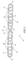
- FIG. 1 the cross section of the extruded composite profile 10 is shown as obtained by extrusion.
- This composite profile 10 consists of two individual tubes 20, 30, each having a flat profile cross-section with two parallel broad sides 21, 22 and 31, 32 and two connecting these curved narrow sides 23, 24 and 33, 34th Die Einzelrohre 20, 30 Sind in the extruded composite profile 10 arranged side by side and connected to each other at its narrow side 24, 34 via a composite site 40. It is of course also conceivable that more than two individual tubes are connected to each other via a respective compound site 40. Furthermore, the broad sides 21, 22 and 31, 32 connecting narrow sides 23, 24 and 33, 34 may also be designed just.
- the individual tubes 20, 30 have a same external and internal geometry in this embodiment.
- the individual tubes 20, 30 may also have a different external and / or internal geometry. As a rule, however, the height of the individual tubes 20, 30 will be the same, and preferably only the width and internal geometry of the individual tubes 20, 30 vary.
- the in the Fig. 1 shown individual tubes 20, 30 each show four channels 25, 35 which are separated by channel walls 26, 36 from each other. Another possible internal geometry of the individual tubes is in the Fig. 4 shown.
- the individual tubes 20, 30 need not have a flat profile cross-section. There are also other cross-sectional shapes, such as round or oval single tubes, possible.
- a composite profile 10 ' is shown, which alternately juxtaposed and over composite sites 40' interconnected individual tubes 20 ', 30' has.
- the outer diameter of all individual tubes 20 ', 30' is the same, but the inner diameter is different.
- Such a composite profile 10 ' is suitable for the flow of different media. It can be used for example as an internal heat exchanger in motor vehicles.
- a separation of the composite profile 10 'can take place between each individual tube 20', 30 'or only selected composite sites 40' are separated in order to obtain a desired width of the composite profile.
- the wall of the individual tubes 20, 30 of a uniform wall thickness is the wall of the individual tubes 20, 30 of a uniform wall thickness.
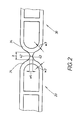
- the wall thickness w2 of the narrow side 24 and the wall thickness w3 of the narrow side 34, which via the composite site 40th Preferably, the wall thickness w4 of the composite 40 should be at least 20% less than the wall thickness w2 and w3 of the adjacent narrow sides 24, 34.
- the width b of the composite 40 is minimal to choose, preferably, the width b of the composite site 40 is between 0.1 to 1.5 mm, more preferably widths b are from 0.1 to 0.5 mm.
- the composite site 40 can advantageously be provided with one or two predetermined breaking points 42, 43, which are then preferably arranged centrally and opposite one another.
- the composite site 40 is in the Fig. 1 and 2 arranged offset by a shoulder 41, so that the connection of the individual tubes 20, 30 takes place in the radius range.
- FIG. 3 a further composite profile is shown, which has individual tubes 20, 30 with parallel broad sides and curved narrow sides.
- the composite point 40 extends from the radius tip 27 of the single tube 20 to the radius tip 37 of the single tube 30.
- an extruded composite profile of three individual tubes is constructed, wherein the individual tubes are not extruded juxtaposed in a plane, but the composite profile shows a zigzag profile cross-section.
- the connection of the individual tubes in This composite profile is realized via the composite site, which does not necessarily take place in the radius area but at the respective radius peak.
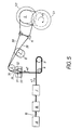
- the above-described extruded composite profiles 10 - as in the Fig. 5 shown - after they leave the extrusion die of the extruder (A) are coated in a subsequent processing step (B).
- a subsequent processing step B
- the composite profile 10 usually passes through a drying device (C).
- a drying device C
- the Fig. 5 is shown in a schematic diagram of the manufacturing process.
- the composite section 10 leaves the extruder (A) with a strand exit speed (v1) passes through, if necessary, a coating device (B) and then a drying or cooling device (C) before the extruded composite profile 10 is fed to a speed control device (D).
- this speed control device (D) the strand exit speed (v1) of the composite profile 10 from the extruder and the speed (v3) of the winding device (S) are adjusted, ie the composite profile 10 leaves the speed control device (D) at a uniform speed (v2). which corresponds to the speed (v3) of the winding device (S).
- the adjustment of the speeds in this case by means of a dancer device, ie two rollers, wherein at least one roller (R) relative to the second roller is movable.
- This roller (R) can thus lengthen the path which the composite profile 10 undergoes in the dancer device (D) and thus bring about a lowering of the speed.
- other speed control devices (D) can be used, namely a control via a Switzerlandcraftkontrolle, for example, a so-called torque control.
- the at uniform speed (v2) emerging from the dancer device (D) composite profile 10 passes - as in Fig. 5 shown - then in a separator (E).
- the composite profile 10 is torn into two separate strands of the individual tubes 20, 30.
- Such tearing can be done by horizontal zipper-like opening of the connection between the two juxtaposed strands of the individual tubes 20, 30 at the joint 40.
- the individual tubes 20, 30 are moved away from each other laterally.
- one strand for example the single tube 20 is moved upwards and the other strand, for example the single tube 30, is moved downwards.
- the composite profile strand 10 is detected by a pair of guide rollers 50 and then pulled apart. This is supported by two further pairs of guide rollers 51, 52, which hold the individual strands of the individual tubes 20, 30 in the extended position and out of the separator (E).
- Fig. 6 shows a further arrangement for a separating device (E).
- a wedge-shaped tool K is provided, which is arranged between the first guide roller pair 50 and the guide roller pairs 51, 52 provided for tearing. This wedge-shaped tool K supports the uniform breaking of the connection between the individual tubes 20, 30.
- the severing of the composite 40 may also be done solely by the tool K, as in FIG Fig. 7 shown.
- the guide rollers 51, 52 serve only to lead out the strands of the individual tubes 20, 30 from the separator.
- a separating device (E) in which a separation of the composite profile strand 10 is carried out by bending.
- Fig. 8a and 8b it can be seen, the flat composite profile strand 10 by different pairs of rollers 53, 50, 54 out.
- Fig. 8a if the compound profile is an in Fig. 1 shown extruded composite profile 10, in which two juxtaposed in a plane single tubes 20, 30 are connected to each other via the composite site 40.
- the previously flat composite profile 10 is bent around the joint 40 until the wall of the single tube 20 almost touches the wall of the single tube 30.
- appropriate circumferential profilings are provided in the forming rollers.
- the upper tapered forming roll of FIG. 53 shows - as in FIG Fig. 8b shown - a central concave, triangular indentation and the lower roller a corresponding convex, triangular bulge.
- the distance of the rollers corresponds approximately to the height of the composite profile or the heights of the individual tubes.
- the concave indentation and convex bulge effect the desired flexure deflection of the individual tubes 20, 30 about the bond site 40 with the bond site 40 positioned in the apex of the triangular bump.
- Deformation of the individual tubes 20, 30 during bending deformation is avoided in that the profiles of the forming rollers of the forming roller pair 53 and also of the subsequent forming roller pairs, for example 54, only Allow bending movements smaller than the maximum bending angles ⁇ or ⁇ for the composite profile 10.
- Fig. 3 These maximum bending angles ⁇ , ⁇ are shown for a composite profile. They arise when starting from the center M of the compound 40, a tangent to the single tube 20 or 30 above and below the composite 40. Above the composite point 40 results in the maximum bending angle ⁇ .
- the individual tubes 20, 30 of the planar composite profile 10 above the compound point toward each other will touch at a bending around the bending angle ⁇ .
- the forming rollers may only allow a bend up to the maximum bending angle ⁇ or ⁇ .
- the maximum bending angle ⁇ has been considered.
- a single bend does not usually result in splitting of the bond site 40, so that multiple back and forth bends are made.
- a total of 3 pairs of rollers 53, 50, 54 are listed.
- the number of bending stations in the separating device (E) can be increased as desired. For very small bending deflections comparatively more bending steps are needed than for larger deflections.
- a bending-separating device and composite profiles as in Fig. 4 shown, be separated.
- the extruded composite profile Fig. 4 already has a zigzag cross-section.
- the first bending step can be chosen so that after the first bend results in a flat composite profile.
- Fig. 9 are given for possible pairs of roles.
- a cylindrical roller pair 50 is used and obtained from the zigzag profile a flat profile.
- a forming roller pair 53 with a zigzag profiling then the bent composite profile is again bent in a cylindrical roller pair 50 to a flat composite profile.
- This can be followed by further pairs of rollers until the individual strands are obtained separately.
- Fig. 10 shows the pre-switching of a bending step in a method Fig. 7 namely, the combination of a bending device with the use of a wedge-shaped tool K.
- a cylindrical roller pair 50 is provided between the tool K and the forming roller pair 53.
- the coils (S1) and (S2) are part of a winding device (S), arranged side by side in this case. They are driven by a drive (not shown here) at a steady speed (v3).
- This speed (v3) of the coils (S1, S2) corresponds to the speed (v2) of the individual strands 20, 30 in front of the winding device (S).
- the individual coils (S1, S2) can be arranged side by side as shown above but also one above the other. Furthermore, it is possible, but not part of the invention, to use only one coil, wherein the wound up single strands different winding areas of the coil are assigned.
- the composite profile 10 is indicated with a slightly thicker line.
- the individual tubing strands 20, 30 resulting after the separation device (E) are designed to distinguish in a corresponding thinner line. That in this Fig. 5 shown overall method for separately winding two simultaneously extruded single tubes 20, 30 by means of a winding device (S) is an embodiment of the method.
Landscapes
- Engineering & Computer Science (AREA)
- Mechanical Engineering (AREA)
- Extrusion Moulding Of Plastics Or The Like (AREA)
- Winding, Rewinding, Material Storage Devices (AREA)
- Extrusion Of Metal (AREA)
Applications Claiming Priority (3)
| Application Number | Priority Date | Filing Date | Title |
|---|---|---|---|
| DE10243725 | 2002-09-20 | ||
| DE10243725 | 2002-09-20 | ||
| PCT/EP2003/008734 WO2004033122A1 (de) | 2002-09-20 | 2003-08-07 | Stranggepresstes verbundprofil und verfahren zum separaten aufspulen von zwei zeitgleich stranggepressten einzelrohren mittels ei ner spuleinrichtung |
Publications (2)
| Publication Number | Publication Date |
|---|---|
| EP1539389A1 EP1539389A1 (de) | 2005-06-15 |
| EP1539389B1 true EP1539389B1 (de) | 2012-01-11 |
Family
ID=32086833
Family Applications (1)
| Application Number | Title | Priority Date | Filing Date |
|---|---|---|---|
| EP03807781A Expired - Lifetime EP1539389B1 (de) | 2002-09-20 | 2003-08-07 | Verfahren zum erzielen von mindestens zwei separat aufgewickelten einzelsträngen von zeitgleich stranggepressten einzelrohren unter verwendung einer spuleinrichtung |
Country Status (6)
| Country | Link |
|---|---|
| US (1) | US7143622B2 (ja) |
| EP (1) | EP1539389B1 (ja) |
| JP (1) | JP4389251B2 (ja) |
| AU (1) | AU2003300090A1 (ja) |
| DK (1) | DK1539389T3 (ja) |
| WO (1) | WO2004033122A1 (ja) |
Families Citing this family (4)
| Publication number | Priority date | Publication date | Assignee | Title |
|---|---|---|---|---|
| WO2009155949A1 (en) * | 2008-06-26 | 2009-12-30 | H. Folke Sandelin Ab | Metal extrusion of product comprising parts designed to be post-extrusion disconnected from each other |
| JP2013071176A (ja) * | 2011-09-29 | 2013-04-22 | Mitsubishi Alum Co Ltd | アルミニウム製細管の製造方法 |
| CN110202019A (zh) * | 2019-07-03 | 2019-09-06 | 安徽澳德矿山机械设备科技股份有限公司 | 一种双金属管坯的制备方法及其制备模具 |
| KR20240050934A (ko) * | 2022-10-12 | 2024-04-19 | 삼성전자주식회사 | 모세관의 제조 방법 |
Family Cites Families (11)
| Publication number | Priority date | Publication date | Assignee | Title |
|---|---|---|---|---|
| US3477126A (en) * | 1967-11-17 | 1969-11-11 | Reynolds Metals Co | Method of making strip conductor material |
| US3862557A (en) * | 1972-02-07 | 1975-01-28 | Alexander Zeitlin | Apparatus and method for hydrostatic extrusion |
| US4203311A (en) * | 1978-03-27 | 1980-05-20 | Peerless Of America, Inc. | Tubular articles of manufacture and method of making same |
| DE3131155A1 (de) | 1981-08-06 | 1983-02-24 | Julius & August Erbslöh GmbH + Co, 5600 Wuppertal | "verfahren zur herstellung von strangpressprofilen aus leichtmetall" |
| JPS60197555A (ja) * | 1984-03-19 | 1985-10-07 | Fuji Photo Film Co Ltd | ウエブ巻取装置のユニツト構造 |
| DE3602128A1 (de) * | 1986-01-24 | 1987-07-30 | Teves Gmbh Alfred | Schlupfgeregeltes bremsensystem fuer kraftfahrzeuge |
| US5186244A (en) | 1992-04-08 | 1993-02-16 | General Motors Corporation | Tube design for integral radiator/condenser |
| CA2141924C (en) | 1994-03-02 | 2003-08-19 | Michael J. Sinn | Method of making pressure sensitive adhesive tape rolls with a transparent to the core appearance |
| WO2000023205A1 (en) | 1998-10-20 | 2000-04-27 | Reynolds Aluminium Holland B.V. | Method for the production of multi-channel tubes; multi-channel tubes obtained in this way; and an extrusion die and installation for carrying out the method |
| DE10058276A1 (de) | 2000-11-23 | 2002-05-29 | Sms Demag Ag | Einrichtung zum Trennen von Spaltband |
| US20020121120A1 (en) | 2001-01-03 | 2002-09-05 | Kraft Frank F. | Method and apparatus for manufacturing extruded parts |
-
2003
- 2003-08-07 EP EP03807781A patent/EP1539389B1/de not_active Expired - Lifetime
- 2003-08-07 DK DK03807781.4T patent/DK1539389T3/da active
- 2003-08-07 AU AU2003300090A patent/AU2003300090A1/en not_active Abandoned
- 2003-08-07 US US10/528,325 patent/US7143622B2/en not_active Expired - Lifetime
- 2003-08-07 JP JP2004542295A patent/JP4389251B2/ja not_active Expired - Lifetime
- 2003-08-07 WO PCT/EP2003/008734 patent/WO2004033122A1/de active Application Filing
Also Published As
| Publication number | Publication date |
|---|---|
| US7143622B2 (en) | 2006-12-05 |
| JP2006500226A (ja) | 2006-01-05 |
| WO2004033122A1 (de) | 2004-04-22 |
| DK1539389T3 (da) | 2012-03-19 |
| JP4389251B2 (ja) | 2009-12-24 |
| EP1539389A1 (de) | 2005-06-15 |
| US20050217340A1 (en) | 2005-10-06 |
| AU2003300090A1 (en) | 2004-05-04 |
Similar Documents
| Publication | Publication Date | Title |
|---|---|---|
| EP1652651B1 (de) | Vorrichtung und Verfahren zum Führen und Formen eines extrudierten Kunststoffstranges | |
| EP2212039B1 (de) | Verfahren zum herstellen eines profils aus flachem metallband | |
| DE4310547C2 (de) | Verfahren und Vorrichtung zum Verhindern der seitlichen Verbiegung einer sich längs erstreckenden, gewalzten Bramme | |
| DE3733058A1 (de) | Verfahren zur herstellung duennwandiger metallrohre | |
| EP1128916B1 (de) | Verfahren zum herstellen eines profils unterschiedlicher wandstärke | |
| DE1940341B2 (de) | Verfahren und Einrichtung zum Herstellen von Metalleisten, insbesondere von rohrförmigen Schweißelektroden, aus einem Stabmaterial | |
| EP1539389B1 (de) | Verfahren zum erzielen von mindestens zwei separat aufgewickelten einzelsträngen von zeitgleich stranggepressten einzelrohren unter verwendung einer spuleinrichtung | |
| EP0662357B1 (de) | Verfahren und Vorrichtung zum Betreiben einer Stranggiessanlage | |
| DE4243857C1 (de) | Verfahren zum Herstellen eines Stahlbandes durch Gießen eines Stranges und anschließendes Walzen | |
| DE3103608C2 (de) | Verfahren zur Herstellung von Draht aus Metall | |
| EP1371430B1 (de) | Verfahren und Vorrichtung zum Herstellen eines Hohlprofils | |
| WO2001019545A1 (de) | Verfahren und vorrichtung zur herstellung eines eine wellung aufweisenden wellblechs | |
| DE10110035B4 (de) | Auslaufeinrichtung einer Strangpressanlage | |
| EP1420901B1 (de) | Verfahren und vorrichtung zum strangpressen von gekrümmten strangspressprofilen | |
| DE10218575B4 (de) | Trennvorrichtung für bandförmiges Halbzeug mit Sollbruchstellen | |
| DE1814950B2 (de) | Universalgerüst zum Herstellen von asymmetrischen, H-förmigen Stahlprofilen | |
| WO2002072292A1 (de) | Verfahren zum strangpressen und strangpressanlage, insbesondere zum herstellen von gekrümmten strangpressprodukten | |
| EP2959985B1 (de) | Profilträger mit einer erhöhten biegefestigkeit aus kaltband sowie verfahren zur herstellung eines solchen | |
| DE10291923B4 (de) | Verfahren und Anlage zum vertikalen Stranggießen eines Stahlbandes | |
| DE1496047B2 (de) | Vorrichtung zur kontinuierlichen herstellung von u-profilen aus in poastischem zustand befindlichen glasbaendern | |
| DE102006004310A1 (de) | Anlage und Verfahren zum Herstellen einer Dünnbramme | |
| EP2208555B1 (de) | Walzverfahren und Walzvorrichtung zum Herstellen eines Metallbands mit einer über seine Breite variierenden Dicke | |
| DE69926406T2 (de) | Verfahren und vorrichtung zum rollformen von stahlrohren | |
| EP1356887A2 (de) | Vorrichtung zum Trennen bandförmigen Halbzeugs mit Sollbruchstellen | |
| DE10162433B4 (de) | Verfahren und Vorrichtung zum Vortreiben von Metallbändern |
Legal Events
| Date | Code | Title | Description |
|---|---|---|---|
| PUAI | Public reference made under article 153(3) epc to a published international application that has entered the european phase |
Free format text: ORIGINAL CODE: 0009012 |
|
| 17P | Request for examination filed |
Effective date: 20050211 |
|
| AK | Designated contracting states |
Kind code of ref document: A1 Designated state(s): AT BE BG CH CY CZ DE DK EE ES FI FR GB GR HU IE IT LI LU MC NL PT RO SE SI SK TR |
|
| AX | Request for extension of the european patent |
Extension state: AL LT LV MK |
|
| DAX | Request for extension of the european patent (deleted) | ||
| RBV | Designated contracting states (corrected) |
Designated state(s): CZ DE DK |
|
| 17Q | First examination report despatched |
Effective date: 20100319 |
|
| GRAP | Despatch of communication of intention to grant a patent |
Free format text: ORIGINAL CODE: EPIDOSNIGR1 |
|
| RTI1 | Title (correction) |
Free format text: METHOD USING A WINDING DEVICE FOR OBTAINING AT LEAST TWO SEPARATELY WOUND INDIVIDUAL LENGTHS OF SIMULTANEOUSLY EXTRUDED TUBES |
|
| GRAS | Grant fee paid |
Free format text: ORIGINAL CODE: EPIDOSNIGR3 |
|
| GRAA | (expected) grant |
Free format text: ORIGINAL CODE: 0009210 |
|
| AK | Designated contracting states |
Kind code of ref document: B1 Designated state(s): CZ DE DK |
|
| REG | Reference to a national code |
Ref country code: DE Ref legal event code: R096 Ref document number: 50314176 Country of ref document: DE Effective date: 20120315 |
|
| REG | Reference to a national code |
Ref country code: DK Ref legal event code: T3 |
|
| REG | Reference to a national code |
Ref country code: DE Ref legal event code: R082 Ref document number: 50314176 Country of ref document: DE Representative=s name: BUSE, MENTZEL, LUDEWIG, DE Ref country code: DE Ref legal event code: R082 Ref document number: 50314176 Country of ref document: DE Representative=s name: BUSE MENTZEL LUDEWIG PATENTANWAELTE, DE Ref country code: DE Ref legal event code: R082 Ref document number: 50314176 Country of ref document: DE Representative=s name: BUSE MENTZEL LUDEWIG PATENTANWALTSKANZLEI, DE |
|
| PLBE | No opposition filed within time limit |
Free format text: ORIGINAL CODE: 0009261 |
|
| STAA | Information on the status of an ep patent application or granted ep patent |
Free format text: STATUS: NO OPPOSITION FILED WITHIN TIME LIMIT |
|
| 26N | No opposition filed |
Effective date: 20121012 |
|
| REG | Reference to a national code |
Ref country code: DE Ref legal event code: R097 Ref document number: 50314176 Country of ref document: DE Effective date: 20121012 |
|
| REG | Reference to a national code |
Ref country code: DE Ref legal event code: R084 Ref document number: 50314176 Country of ref document: DE |
|
| PGFP | Annual fee paid to national office [announced via postgrant information from national office to epo] |
Ref country code: DK Payment date: 20220818 Year of fee payment: 20 Ref country code: DE Payment date: 20220726 Year of fee payment: 20 Ref country code: CZ Payment date: 20220720 Year of fee payment: 20 |
|
| REG | Reference to a national code |
Ref country code: DE Ref legal event code: R071 Ref document number: 50314176 Country of ref document: DE |
|
| REG | Reference to a national code |
Ref country code: DK Ref legal event code: EUP Expiry date: 20230807 |
|
| PG25 | Lapsed in a contracting state [announced via postgrant information from national office to epo] |
Ref country code: CZ Free format text: LAPSE BECAUSE OF EXPIRATION OF PROTECTION Effective date: 20230807 |